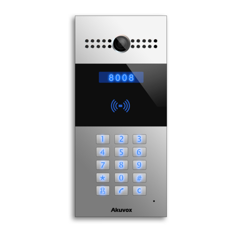
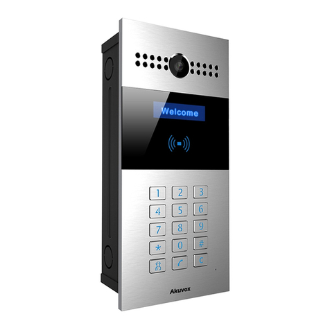
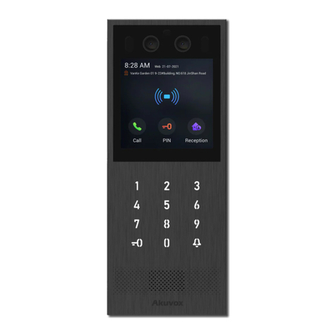
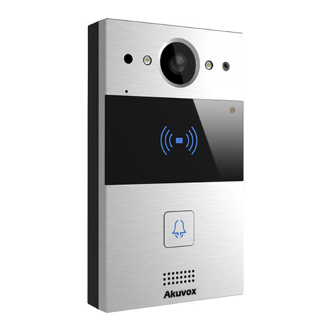
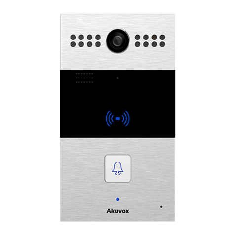
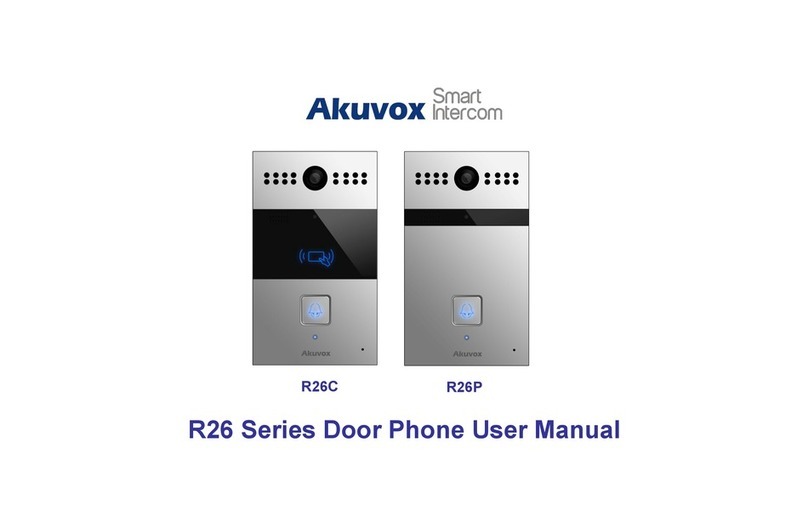
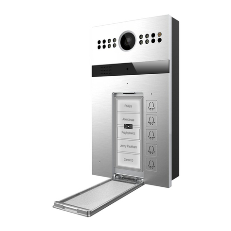
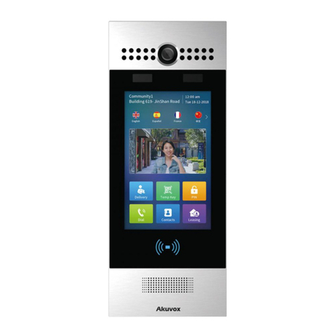
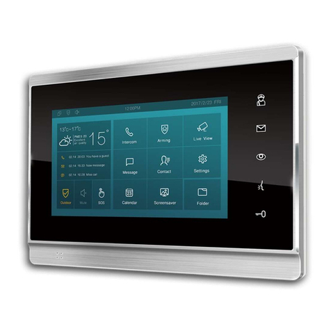
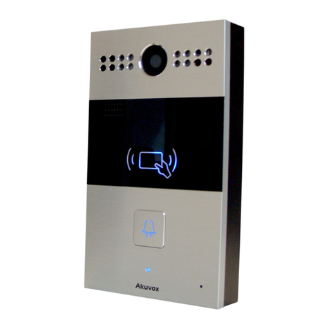
Akuvox R27A User manual

SUPPORT INFORMATION
Akuvox R27A
Quick Start Guide
Rev 01 /2019 EN
Skills:
Table of Contents
1. PHYSICAL INSTALLATION .......................................................................................................................................................................... 2
2. THE R27A CONNECTOR TERMINALS ON THE BACK SIDE:.............................................................................................................. 6
3. WIRING POWER SUPPLY............................................................................................................................................................................. 7
4. THE IP ADDRESS............................................................................................................................................................................................ 8
5. WIRING DOOR STRIKE, LOCK OR MAGNETIC LOCK .......................................................................................................................... 8
6. CONFIGURATION FOR RELAYA................................................................................................................................................................. 9
7. EXTRA RELAY SETTINGS ..........................................................................................................................................................................10
8. WIRING REQUEST TO EXIT PUSH BUTTON........................................................................................................................................10
9. CONFIGURATION FOR INPUT “DOORA” ..............................................................................................................................................11
10. CALL CONFIGURATION EXAMPLE 1 |LOCAL RELAY ON R27A....................................................................................................11
11. CALL CONFIGURATION EXAMPLE 2 | LOCAL RELAY C315 ...........................................................................................................15
12. LOCAL ACCESS CONTROL..........................................................................................................................................................................16
13. ACT ENTERPRISE INTEGRATION ON WIEGAND 32 BIT.................................................................................................................19
14. SPC INTEGRATION ON WIEGAND 32 BIT AND WIEGAND 56 BIT...............................................................................................20
15. TROUBLESHOOTING ..................................................................................................................................................................................21
16. NOTES..............................................................................................................................................................................................................22
Door Entry Phones
25/11/2019
BASIC

Akuvox R27A Quick Start V1-EN
SUPPORT INFORMATION
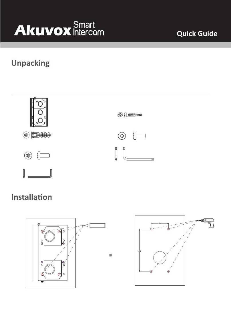
Installation without Backbox:
Flush Mounted: (using the Flush Mounting Bracket)

Akuvox R27A Quick Start V1-EN
SUPPORT INFORMATION

Akuvox R27A Quick Start V1-EN
SUPPORT INFORMATION
Back Cover Installation:
Final Installation:

Akuvox R27A Quick Start V1-EN
SUPPORT INFORMATION
2. The R27A Connector Terminals on the back side:

Akuvox R27A Quick Start V1-EN
SUPPORT INFORMATION
3. Wiring Power Supply
To power the R27A device 2 options are available
•A local 12 Volt Power supply connected to GND and +12V here shown in red
The power Supply should have min rating of 1A at 12 Volts DC.
Recommended cable min 0,6 mm2stranded or single core.
•By using a POE enabled Switch (The POE will power for the R27A Unit)
Connect the ethernet cable having POE into the green highlighted RJ45 port.
Using POE, the red terminal will not provide any power to source the attached locks.
In this case an external Power Supply will be required!
12V DC min 1A
POE Switch
Switch without POE

Akuvox R27A Quick Start V1-EN
SUPPORT INFORMATION
4. The IP Address
By default, the R2/A is configured for using DHCP (automatically assigned IP Addresses). The
automatic assignment of your devices IP will happen automatically after it has started. The
R27 A will get an IP from your Router or DHCP server in your network.
To Access the Devices Web Server for the configuration you can discover the IP address by 2
different steps.
1) Press “*2396#” to enter administrator interface. Press “3” to enter system setting interface,
and press “1” to enter network setting interface. Here you can check or modify the IP
address of the device.
2) You can download the IP Scanner tool from Akuvox and search in your local network for
new units. Link for the IP Scanner and Description.
Manual IP configuration:
To setup a manual IP address you need to enter the Web Client by using a temporary
assigned IP address. Login with default credentials Username = admin, Password = admin.
Navigate to Network > Basic and change the IP address from DHCP to manual and set the
desired address.
More options can be found here at the corresponding Akuvox Wiki Record.
5. Wiring Door Strike, Lock or Magnetic Lock
R27A and Lock is powered by a single PSU
•Normal Operation wiring
•Fail-Safe Operation wiring
Remember to select the right Power Supply in relation to your Locks Power consumption.
Switch without POE

Akuvox R27A Quick Start V1-EN
SUPPORT INFORMATION
R27A is powered via POE, Lock is powered by an external PSU
•Normal Operation wiring
•Fail-Safe Operation wiring
6. Configuration for RelayA
As per chapter 3 discover and use the IP address and login to connect to its Web Server.
Navigate to Intercom > Relay to configure the parameters for the different relays. Most cases
the default values are just perfect.
Press 6 on your phone’s keypad during an active call, to send the corresponding DTMF tone to release the door
on RelayA. Indoor monitors or App’s have soft keys simulating the configured DTMF tone. DTMF Wiki Link
Relay Delay set the door
open time. Default is 3 Sec
we would recommend using 5
Sec.
DTMF define the unlock
Code. Default is “5” but it can
be changed to another value.
Remember your DTMF code
for further intercom settings.
Legend:
Ethernet / POE ◼
Lock Cabling ◼◼
Power Supply ◼◼
Wires ◼
POE Switch

Akuvox R27A Quick Start V1-EN
SUPPORT INFORMATION
7. Extra Relay settings
Several extra Settings can be applied to each relay.
8. Wiring Request to Exit Push Button
This configuration will allow to use a standard switch to release the door by remote. Normally
this is used if the door has a card reader from the Entrance direction, and a release button
from the inside.
NO Contact
Press (close circuit) to unlock
Door
Relay Type
By this setting you can
inverse the relay if needed.
Example use case can be a
fail-safe operation for the door
lock.
Relay Mode
Monostable = momentary
switching for the Delay time.
Bistable = Keep the state of
the relay until triggered next
time ( Toggle mode )

Akuvox R27A Quick Start V1-EN
SUPPORT INFORMATION
9. Configuration for Input “DoorA”
Open the Web Server and navigate to Intercom > Input. In this section you can configure the
behaviour of individual inputs. To enable the “DoorA” Input as Request to Exit Button apply the
illustrated changes.> The door will open for the configured delay time on the selected relay
once the contact has been closed.
10. Call Configuration Example 1 |Local Relay on R27A
The R27A is combined with 2x C315 Indoor monitors to pick up a call from the door.
Out of the box the C315 Monitors will have the most necessary settings configured already.
In each C315 Monitor only the unlock features for the doors must be configured to get a
working system in place.
Trigger Option set the input
trigger mode.
Low means contact closing
High means contact opening
Open Relay define the relay
you like to control by this
input.
Door Status show the current
input state (in real time)
POE Switch
Door Strike
Example IP
192.168.1.100
Example IP
192.168.1.101
Example IP
192.168.1.102

Akuvox R27A Quick Start V1-EN
SUPPORT INFORMATION
The Setup:
Step1: Get the C315 Monitors connected via DHCP to your network.
Step2: Write down the give IP address of each C315S unit to be configured in the R27A later.
Tipp: Most networks support a DHCP reservation for devices, so they will always have
the same IP Address assigned. Please use this feature for optimal system performance.
Step3:Configure each C315S with the remote relay Unlock DTMF command “6”
On the C315 units Navigate to Phone > Relay and set the remote relay settings for your R27A.
•Configure the common DTMF Command
On the relay settings page set the remote Relay DTMF to your selected character
•Configure the Soft Key(s) for the Talking Screen (incoming calls).
This example will just show one “Open Door” Soft Key in the Talking Screen here configured
as “Soft Key 0”
Used to remote control
the relay from the
R27A

Akuvox R27A Quick Start V1-EN
SUPPORT INFORMATION
Step4: Configure the local contacts in your R27A to be able to call the different receivers from your
R27A calling screen
Navigate to Phone Book > Phone Book and configure the IP Addresses of each C315 Monitor as a
call receiver. The illustration will show a new contact created with the following settings:
Name
Set the name of the resident also shown in the contact list on the R27A screen
Phone
Phone Number, Sip Account or IP address of the Resident
Priority of Call
The priority of this resident, call as first, 2nd or 3rd choice

Akuvox R27A Quick Start V1-EN
SUPPORT INFORMATION
Step5: Test call by using the screen menu on the R27A
By default, you have 3 options to select on the home screen
1-> Enter a password for Temporary Access
2-> Call the Residents
3-> Dial By Room Number (Cloud Feature)
Select “2”and it will show the local configured residents on the R27A.
By using the buttons 2and 8you can navigate up and down in the list to select the resident
you like to call.
Finally, after the right party has been selected like here “Andy”, press the Phone
Key to dial.
If all settings are done to correct way, the other party, in this case Andy’s Indoor Screen
will start to ring and show the Incoming call screen with the video preview of the R27A’s
camera.

Akuvox R27A Quick Start V1-EN
SUPPORT INFORMATION
11. Call configuration Example 2 | Local Relay C315
This example will be based on the previous example 1, but as big difference we are going to
link the door lock to the Local Relay of one of the C315S Indoor monitors. This is a more
secure solution, as the relay is installed inside of the secure area.
C315S Connection Schema for the door Lock locally connected:
POE Switch
Door Strike
Example IP
192.168.1.102
Example IP
192.168.1.100
Example IP
192.168.1.101
C315S and Lock powered from the same PSU
Power Supply Variant
POE powered C315S / Lock locally supplied
POE Switch
Switch without POE

Akuvox R27A Quick Start V1-EN
SUPPORT INFORMATION
The Setup:
Step1-2 are the same as the previous Example1
Step3:Configure the first C315S DTMF code and Relay settings as below
On the C315 units having the relay connected, Navigate to Phone > Relay and set the relay
settings for Local Relay1
•Configure the Relay Type at Local Relay to Open Door with the desired Delay timer
•Set the Remote Relay DTMF Code1 to “6” (Your common DTMF code)
•Configure the Soft Keys for the Talking screen.
This sample will just show one “Open Door” Soft Key in the Talking Screen what is Key 0
Here the difference to example 1 is the relay set for Local Relay1
12. Local Access control
This R27A Door Entry phone comes with an onboard Access control system, able to hold up
to 500 cards for local Access control. The reader embedded can read Mifare Classic, Mifare
Desfire as well as EM4102 EM cards based on 125kHz.
How to configure cards into the R27A
Step1:
Open the R27A Web Client and navigate Navigate to Phone > Card Settings

Akuvox R27A Quick Start V1-EN
SUPPORT INFORMATION
Step2:
To learn new card’s, you first select as Card Status “Card Issuing” and Apply.
Step3:
Fill out the highlighted fields in card Settings and finally click “Optain” to enrol the card
presented at the reader.
Finally:
Press Add to store the card.
Test:
Show the configured card on the R27A’s card reader and if the settings are correct and the
allowed time is valid, you will see an UNLOCK message on the LCD screen together with a
voice message saying “The Door has been open“.
Before you can use
the schedules, they
need to be
configured in
Intercom >
Schedules

Akuvox R27A Quick Start V1-EN
SUPPORT INFORMATION
The configuration for local Access Control cards can be seen on the Door Card Management
list in Intercom > Card Settings.
To check the Access control logs, please navigate to the Phone > Door Log

Akuvox R27A Quick Start V1-EN
SUPPORT INFORMATION
13. ACT Enterprise integration on Wiegand 32 Bit
The Wiegand 32 Bit will be supported by the default activated Wiegand Card formats in the
ACT Enterprise 2.9.xx and later systems. On the ACT Enterprise side, no extra settings will be
required.
The Wiegand 32 Bit can ready the full 4Byte UID from a Mifare / Desfire card.
If a 7Byte card will be used, ACT will just receive the first 4 Byte from the provided 7Byte as
card number.
R27A has not the capability to reduce the provided 7Byte to 4Byte same as the ACT /
Vanderbilt readers will do. This is only possible on R29S by today but planned as
improvement for R27A in the future! Today the R27 Will just send the first 4 Byte, as the
readers will ignore the first Byte, send the coming 4Byte and ignore the rest of the following
bytes as ACT standard.
The Wiring between R27A and the ACT Enterprise 1500e Controller
The Wiring between R27A and the ACT Enterprise 100e Controller
Make sure the R27A and the ACT controller have the ground signal connected to have a
common Ground for both devices, otherwise the Wiegand Signal will float.

Akuvox R27A Quick Start V1-EN
SUPPORT INFORMATION
Settings on the R27A for Wiegand 32 Output
Navigate to Intercom > Advance and select the displayed configuration
The CRC turned off will turn down the selected 34 Bit to 32 Bit card data send to the Access
control System.
14. SPC integration on Wiegand 32 Bit and Wiegand 56 Bit
SPCA210 Door Controller
Wiegand 34 Bit will be read in SPC with card format HID ICLASS MIFARE (32 Bit Card Data)
This can be used for 4 Byte Mifare Cards (UID)
Wiegand 58 Bit will be read in SPC with card format HID ICLASS DESFIRE (56 Bit Card Data)
This can be used for 4 or 7 Byte Desfire or Mifare cards (UID)
VDx
VAx
D0
D1
+12V
0V
Other manuals for R27A
3
Table of contents
Other Akuvox Intercom System manuals

Akuvox
Akuvox E21A User manual

Akuvox
Akuvox X912 User manual

Akuvox
Akuvox IT88 Series Manual

Akuvox
Akuvox R20A-2 Series User manual

Akuvox
Akuvox R28 Series Service manual

Akuvox
Akuvox C313 Series User manual

Akuvox
Akuvox X912 User manual

Akuvox
Akuvox C313 Series User manual

Akuvox
Akuvox E10S User manual

Akuvox
Akuvox IT82A Manual

Akuvox
Akuvox X915 Series Service manual

Akuvox
Akuvox E12 User manual

Akuvox
Akuvox R26 User manual

Akuvox
Akuvox R26X User manual

Akuvox
Akuvox R20A User manual

Akuvox
Akuvox E16 Series Service manual

Akuvox
Akuvox IT83 Series User manual

Akuvox
Akuvox E21 Series User manual

Akuvox
Akuvox X933 Series Service manual

Akuvox
Akuvox IT82 Series User manual