Alcad KVS-44101 User manual

MONITOR
MONITOR
MONITEUR
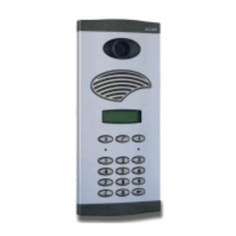
PLACA DE CALLE
ENTRANCE PANEL
PLAQUE DE RUE
MONITOR
MONITOR
MONITEUR
ÍNDICE
DESCRIPCIÓN ..........................................................................................................................................................................2
ELEMENTOS QUE CONSTITUYEN EL KIT....................................................................................................................................2
FUNCIONAMIENTO DEL SISTEMA DE VIDEOPORTERO............................................................................................................11
INSTALACIÓN EN VIVIENDA UNIFAMILIAR .............................................................................................................................12
INSTALACIÓN BÁSICA DOS VIVIENDAS .................................................................................................................................14
INSTALACIÓN DE 2 MONITORES EN PARALELO .....................................................................................................................16
INSTALACIÓN DE 1 MONITOR CON 1 TELÉFONO EN PARALELO............................................................................................17
INSTRUCCIONES DE INSTALACIÓN ........................................................................................................................................18
INSTRUCCIONES DE A USTE...................................................................................................................................................24
CARATERÍSTICAS TÉCNICAS ...................................................................................................................................................26
VERIFICACIÓN DE LA INSTALACIÓN.......................................................................................................................................28
INDEX
DESCRIPTION ...........................................................................................................................................................................5
INCLUDED IN THE KIT ...............................................................................................................................................................5
OPERATION OF THE VIDEO DOOR ENTRY SYSTEM .................................................................................................................11
INSTALLATION IN DETACHED HOUSES ...................................................................................................................................12
BASIC INSTALLATION FOR 2 HOUSES OR FLATS......................................................................................................................14
INSTALLATION OF TWO MONITORS IN PARALLEL ...................................................................................................................16
INSTALLATION OF 1 MONITOR AND 1 TELEPHONE IN PARALLEL ............................................................................................17
INSTALLING INSTRUCTIONS ...................................................................................................................................................18
AD USTMENT INSTRUCTIONS.................................................................................................................................................24
TECHNICAL CHARACTERISTICS...............................................................................................................................................26
TROUBLE SHOOTING .............................................................................................................................................................29
SOMMAIRE
DÉSCRIPTION...........................................................................................................................................................................8
ELÉMENTS CONSTITUANT LE KIT ..............................................................................................................................................8
FONCTIONNEMENT DU SYSTEME DE VIDEOPORTIER..............................................................................................................11
INSTALLATION INDIVIDUEL .....................................................................................................................................................12
INSTALLATION STANDARD POUR 2 LOGEMENTS....................................................................................................................14
INSTALLATION DE DEUX MONITEURS EN PARALLÈLE...............................................................................................................16
INSTALLATION DE 1 MONITEUR ET 1 TÉLÉPHONE EN PARALLEL...............................................................................................17
INSTRUCTIONS D'INSTALLATION ............................................................................................................................................18
INSTRUCTION DE RÉGLAGE ...................................................................................................................................................24
CARACTÉRISTIQUES TECHNIQUES..........................................................................................................................................26
PROBLÈMES DE FONCTIONNEMENT ......................................................................................................................................30
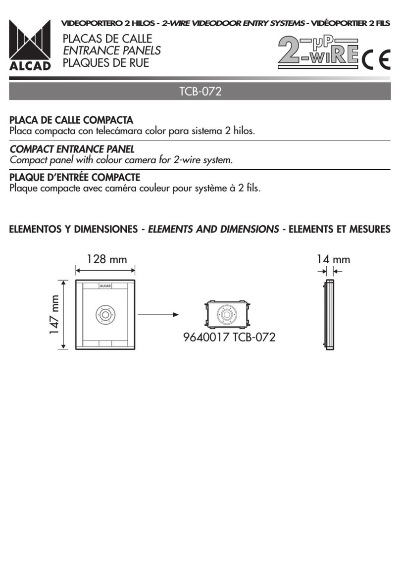
COAXCOAX
KITS
KITS
KITS
VIDEOPORTERO ELECTRÓNICO - VIDEODOOR ENTRY SYSTEMS - VIDÉOPORTIER ÉLECTRONIQUE
128 mm
195 mm
12 mm
160 mm
25 mm31 mm
100 mm30 mm
3 mm
106 mm
90 mm
60 mm
230 V230 V V
166 mm
193 mm
45 mm
114 mm
179 mm
ARRIBA
UP
HAUT
DESCRIPCIÓN
El videoportero electrónico permite no sólo controlar el acceso a la propiedad de personas externas, sino también visualizar a la
persona que realiza la llamada. El kit de videoportero electrónico es la solución más cómoda para realizar instalaciones tanto en
viviendas unifamiliares como en instalaciones con 2 viviendas. Con el kit que acaba de adquirir dispone de todos los elementos
necesarios para realizar su instalación de videoportero electrónico.
Características:
Es posible instalar hasta 2 monitores y 2 teléfonos convencionales por vivienda con la misma llamada.
La conexión comprende 4 hilos comunes hacia los monitores/teléfonos de las viviendas, 2 hilos para alimentación de los monitores
de la instalación y cable coaxial para la transmisión de la señal de vídeo. De esta manera, a cada teléfono de la instalación le
llegarán 5 hilos (4 comunes + hilo de llamada) mientras que a los monitores le llegarán 7 hilos (4 comunes + hilo de llamada + 2
hilos para la alimentación del monitor) más el cable coaxial de la señal de vídeo.
2
COAX
65 COAX
PLACA DE CALLE
ALIMENTADOR
2
2
2 2
GRF-204
TCB-011
GRF-204
TCB-011
1 VIVIENDA
55
ALIMENTADOR
PLACA DE CALLE
2 VIVIENDAS
Soporte de conexiones
ELEMENTOS QUE CONSTITUYEN EL IT
Placa de calle Caja de empotrar
Abrepuertas
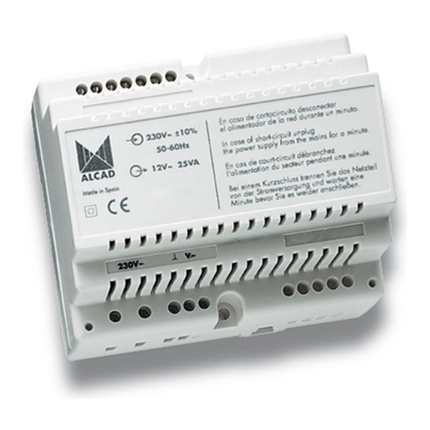
Alimentador
VIDEOPORTERO ELECTRÓNICO - VIDEODOOR ENTRY SYSTEMS - VIDÉOPORTIER ÉLECTRONIQUE

64.3 mm
197 mm
224 mm
Monitor

3
PLACA DE CALLE
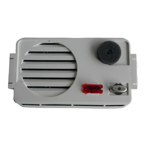
Placa de exterior. Aloja en su interior el grupo fónico, la telecámara
y los grupos de pulsadores. Los circuitos electrónicos están protegidos
contra cortocircuito.
9610030 GRF-204 GRUPO FÓNICO AUDIO Y VÍDEO CON
SECRETO (1)
Grupo fónico para instalaciones de sistemas convencionales 4+N
con secreto de comunicación. Llamada electrónica, con confirmación
de llamada en la placa de calle. Dotado de dos puentes, uno para
la configuración de la placa como principal y otro para habilitar
el ajuste de precisión del volumen de audio.
Permite realizar una llamada al monitor/teléfono de la vivienda y
mantener una conversación con la vivienda. Activa la telecámara
cuando se pulsa el botón de autoencendido del monitor o cuando
se llama desde la placa de calle. Dispone de regulador de volumen
en la placa (2) en el monitor/teléfono de la vivienda (3) y pulsador
de luz para la placa (4).
9640002 TCB-011 TELECÁMARA GENÉRICA B/N COAXIAL (5)
Telecámara de blanco y negro con sensor CCD 1/3 para instalaciones
de videoportero.
La telecámara dispone de una salida de vídeo compuesto para cable
coaxial 75 ohmios, iluminación infraroja para visión nocturna y
regulador multidireccional del ángulo de visión hasta 10o. (6)
Posibilidad de alimentar la telecámara desde grupo fónico o desde
un alimentador de 15 Vdc. Bornas enchufables para facilitar el
conexionado.
Permite captar la imagen de la persona que realiza la llamada
desde la placa de calle.
9740006 CMO-004 CAJA DE EMPOTRAR MONTADA
La caja de empotrar le permite colocar la placa de calle en el lugar
deseado. Presenta aberturas (1) a diferentes alturas para facilitar
el conexionado con la placa de calle.
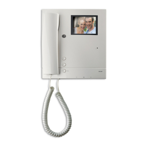
9630000 MVB-001 MONITOR DE VIDEOPORTERO CON SECRETO
DE COMUNICACIÓN
Monitor de superficie con pantalla CRT plana de 4" en blanco y
negro, llamada electrónica.
Consulte el manual de usuario del monitor para conocer sus
características.
CAJA DE EMPOTRAR
MONITOR
VIDEOPORTERO ELECTRÓNICO - VIDEODOOR ENTRY SYSTEMS - VIDÉOPORTIER ÉLECTRONIQUE
25
24
27
26
P1
P2
4
9630002 SCM-010 SOPORTE CONEXIONES MONITOR
Elemento en el que se realizan todas las conexiones del sistema de
videoportero en la vivienda, permitiendo conectar el monitor de
videoportero al resto de la instalación. Sistema 6+N+coaxial. Secreto
de comunicación.
Dispone de 4 bornas de conexión correspondientes a los pulsadores
auxiliares (P1, P2) del monitor (Ver dibujo). Limitación conexión: 50
mA - 12 Vdc.
Fijación directa a pared o a caja de mecanismos universal.
9730000 ABR-001 ABREPUERTAS SIMPLE 12 Vac
Dispositivo eléctrico que permite la apertura de la puerta. Abre la
puerta de la calle cuando recibe la tensión de 12 Vac proporcionada
por el grupo fónico. Permanece activado mientras que se pulse el
botón del teléfono de la vivienda.
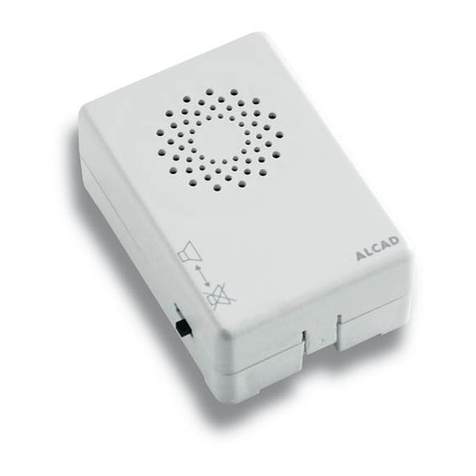
9620006 ALM-041 ALIMENTADOR IT AC-DC 25VA 230/240 Vac
El alimentador convierte la tensión de red en las tensiones necesarias
para el funcionamiento del sistema de videoportero electrónico.
Formato carril DIN 6 elementos, para montaje en pared o carril. El
alimentador está protegido contra cortocircuitos.
VIDEOPORTERO ELECTRÓNICO - VIDEODOOR ENTRY SYSTEMS - VIDÉOPORTIER ÉLECTRONIQUE
SOPORTE DE CONEXIONES
ALIMENTADOR
ABREPUERTAS

128 mm
195 mm
12 mm
160 mm
25 mm31 mm
100 mm30 mm
3 mm
106 mm
90 mm
60 mm
230 V230 V V
166 mm
193 mm
45 mm
114 mm
179 mm
ARRIBA
UP
HAUT
5
COAX
65 COAX
ENTRANCE PANEL
POWER SUPLY
2
2
2 2
GRF-204
TCB-011
GRF-204
TCB-011
1 FLAT
55
POWER SUPLY
ENTRANCE PANEL
2 FLATS
DESCRIPTION
The videodoor entry system allows not only control the access of persons to your property but see who is calling as well. The videodoor
entry system kit is the most comfortable solution for carrying out installations in detached or semi-detached houses. The kit that you
have just bought has all the necessary components for you to carry out your own videodoor entry system installation. There follows a
short description of the items contained in the kit.
Characteristics
It is possible to install up to 2 monitors and 2 telephones per apartment.
Connection is by means of 4 common wires to the monitors/telephones of the flats, 2 wires supplying power to the monitors of the
installation and 1 coaxial cable for the transmission of the video signal. Thus, for each telephone of the installation there are 5 wires
(4 common + 1 call wire) whereas for each monitor there are 7 wires (4 common + 1 call wire + 2 wires to supply power to the
monitor) plus the coaxial cable for the video signal.
INCLUDED IN THE KIT ARE THE FOLLOWING
Entrance panel Flush-mounted box
Lock release
Power supply
Connection bracket
VIDEOPORTERO ELECTRÓNICO - VIDEODOOR ENTRY SYSTEMS - VIDÉOPORTIER ÉLECTRONIQUE
64.3 mm
197 mm
224 mm
Monitor

6
ENTRANCE PANEL
610030 GRF-204 AUDIO UNIT FOR AUDIO AND VIDEODOOR
WITH PRIVACY OF CONVERSATION (1)
Audio unit for conventional 4+N system with confidentiality feature.
The call is electronic, with call-confirmation on the entrance panel.
Equipped with two jumpers, one to configure the entrance panel as
the main panel, the other to enable precision adjustment of sound
level.
Allows you to make calls to the monitor in a house and have a
conversation with the house. It activates the video unit when the auto
switch-on button is pressed in the monitor or when a call is made
from the entrance panel. The audio unit consists of a volume control
on the panel (2) and telephone/monitor and light switch for the
panel (4).
640002 TCB-011 GENERIC B/W VIDEO UNIT COAXIAL (5)
Black and white video unit with a 1/3" CCD sensor for videodoor
entry system installations.
The video unit consists of one video output for coaxial cable, infrared
lighting for nocturnal vision and multidirectional controller of the
angle of view - up to 10o. (6)
It is possible to feed the camera from the audio unit or from a power
supply unit of 15Vdc. Plug-type terminals for easy connection.
Captures the image of the person who is calling from the entrance
panel in the street.
740006 CMO-004 ASSEMBLED FLUSH-MOUNTED BOX
The flush-mounted box allows you to fit the entrance panel in any
place you want. It features openings (1) at different heights for easier
connection of the entrance panel.
630000 MVB-001 VIDEODOOR ENTRY SYSTEM MONITOR WITH
CONFIDENTIALITY FEATURE
Surface wall-mounted black and white monitor with 4" CRT flat
screen, electronic call.
Refer to the user's manual to know the features of the monitor.
Outdoor panel. It holds the audio unit, the video unit and the group
of push-buttons The electronic circuits are protected against short-
circuits.
FLUSH-MOUNTED BOX
MONITOR
VIDEOPORTERO ELECTRÓNICO - VIDEODOOR ENTRY SYSTEMS - VIDÉOPORTIER ÉLECTRONIQUE
25
24
27
26
P1
P2
7
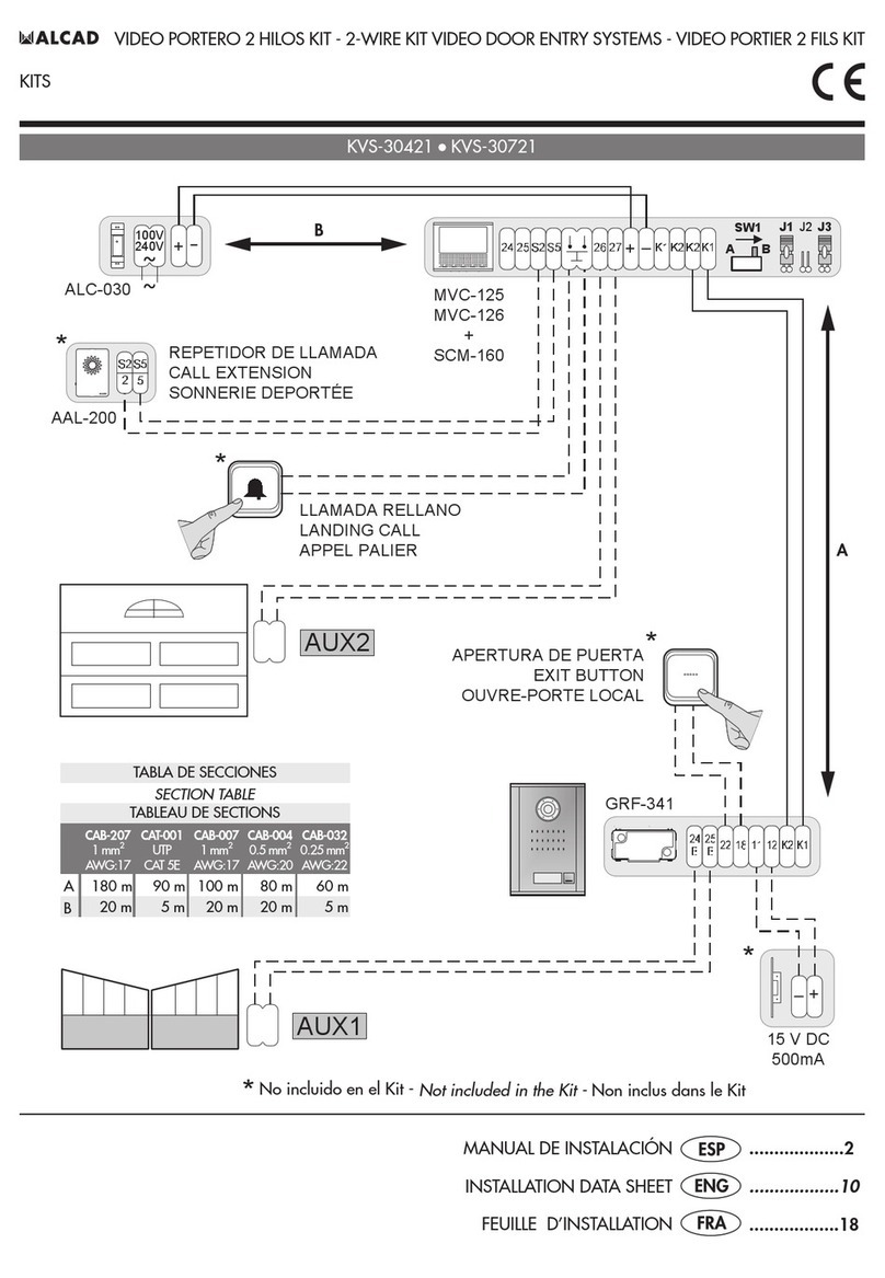
630002 SCM-010 MONITOR CONNECTION BRACKET
Element where all the video entry system's connections are done in
the dwelling, allowing connecting the monitor to the rest of the
installation. 6+N+coaxial system. Privacy of conversation.
With 4 connecting terminals corresponding to the monitor's two
auxiliary push-buttons (P1, P2) (See drawing). Connection limitations:
50 mA - 12 Vdc.
It can be fixed to a wall or standard electrical box fixing.
730000 ABR-001 STANDARD ELECTRIC LOCK 12 Vac
Electric device designed to open the door. It will open the door on
receiving a 12 Vac electric signal through the audio unit. It remains
active as long as you press the button on your telephone.
620006 ALM-041 AC-DC KIT POWER SUPPY 25VA 230/240 Vac
The power supply transforms the mains voltage into tensions suitable
for the proper operation of the the videodoor entry systems. 6 element
DIN rail format, for mounting on walls or rails. The power supply
is protected against short circuits.
CONNECTION BRACKET
POWER SUPPLY
ELECTRIC LOCK
VIDEOPORTERO ELECTRÓNICO - VIDEODOOR ENTRY SYSTEMS - VIDÉOPORTIER ÉLECTRONIQUE
128 mm
195 mm
12 mm
160 mm
25 mm31 mm
100 mm30 mm
3 mm
106 mm
90 mm
60 mm
230 V230 V V
166 mm
193 mm
45 mm
114 mm
179 mm
ARRIBA
UP
HAUT
8
COAX
65 COAX
PLAQUE DE RUE
ALIMENTATION
2
2
2 2
GRF-204
TCB-011
GRF-204
TCB-011
1 LOGEMENT
55
ALIMENTATION
PLAQUE DE RUE
2 LOGEMENTS
DESCRIPTION
Le vidéoportier électronique permet non seulement le contrôle dacces aux personnes à la propriété mais aussi de voir la personne
qui réalise lappel. Le kit vidéo portier électronique est la solution la plus pratique a réaliser aussi bien pour des installations individuelles
comme pour des installations à deux logements. Le Kit que vous venez d'acquérir comprend tous les éléments nécessaires pour réaliser
linstallation de votre vidéoportier électronique. Voici une brève déscription de chacun des éléments composant ce Kit.
Caractéristiques:
Il est possible d'installer jusqu'à 2 moniteurs et 2 téléphones en parallèle.
La connexion comprend 4 fils communs vers les moniteurs / téléphones des logements, 2 fils pour alimenter les moniteurs de
linstallation et un câble coaxial pour la transmission du signal vidéo. De cette manière, à chaque téléphone de linstallation 5 fils
arriveront (4 communs + fil dappel) et 7 fils arriveront aux moniteurs (4 communs + fil dappel+ 2 fils pour lalimentation du moniteur)
ainsi que le câble coaxial du signal de vidéo.
Support de connexions
ELÉMENTS CONSTITUANT LE IT
Plaque de rue Boîtier encastrable
GâcheAlimentation
VIDEOPORTERO ELECTRÓNICO - VIDEODOOR ENTRY SYSTEMS - VIDÉOPORTIER ÉLECTRONIQUE
64.3 mm
197 mm
224 mm
Moniteur

9
9610030 GRF-204 GROUPE PHONIQUE AUDIO ET VIDEO AVEC
SECRET (1)
Groupe phonique pour installations de systèmes 4+N standard avec
secret de communication. L'appel est électronique avec confirmation
d'appel sur la plaque de rue. Deux cavaliers sont fournis, un pour
la configuration de la plaque désignée comme principale et lautre
pour valider le réglage de précision du volume audio.
permet d'appeler le moniteur du logement et de parler avec les
occupants du logement. Il active la caméra quand le bouton d'auto-
allumage est allumer ou quand un appel de l'extérieur se produit.
Le groupe phonique est composé d'un système de réglage de volume
sur la plaque (2) et sur le téléphone/moniteur (3) et d'un bouton-
poussoir d'éclairage pour la plaque (4).
9640002 TCB-011 CAMÉRA GÉNÉRIQUE N/B CÂBLE COAXIAL (5)
Caméra en noir et blanc avec une cellule CCD 1/3" pour des
installations de vidéoportiers électronique.
La caméra est composé d' une sortie de vidéo par câble coaxial,
illumination infrarouge pour une vision nocturne et régulateur multi-
directionnel de langle de vision - jusquà 10o. (6)
Possibilité dalimenter la télécaméra à partir du groupe phonique
ou à partir dune alimentation de 15 Vdc. Avec bornes à fiche pour
faciliter la connexion.
Permet de capter l'image de la personne qui réalise l'appel de
l'extérieur
9740006 CMO-004 BOÎTIER ENCASTRABLE MONTÉ
Le boîtier encastrable vous permet de poser la plaque de rue à
l'endroit où vous voulez. Il présente des ouvertures (1) à différentes
hauteurs pour un câblage facile à la plaque de rue.
9630000 MVB-001 MONITEUR POUR VIDÉOPORTIER AVEC SECRET
DE COMMUNICATION
Moniteur blanc et noir en saillie, CRT plat de 4", avec appel
électronique.
Consulter le manuel d'utilisation pour obtenir les caractéristiques.
Platine d'extérieur. Elle contient le groupe phonique, la caméra et
le groupe de boutons poussoirs. Les circuits électroniques sont
protégént contre les courts-circuits.
BOÎTIER ENCASTRABLE
MONITEUR
PLAQUE DE RUE
VIDEOPORTERO ELECTRÓNICO - VIDEODOOR ENTRY SYSTEMS - VIDÉOPORTIER ÉLECTRONIQUE
25
24
27
26
P1
P2
10
9630002 SCM-010 SUPPORT DE CONNEXIONS MONITEUR
Pièce où est réalisé les montages des connexions du système du vidéoportier
de lhabitation, permettant de connecter le moniteur du vidéoportier au
reste de linstallation. Système 6+N+coaxial. Secret de communication.
Il est composé de 4 colonnes de connexions correspondantes aux deux
boutons auxiliaires (P1, P2) du moniteur (Voir dessin). Limitation de
connexion: 50 mA - 12 Vdc.
Fixation directe au mur ou en boîtier d'appareillage universel.
9730000 ABR-001 GÂCHE ÉLECTRIQUE SIMPLE
Dispositif électrique commandant lóuverture de la porte d'entrée. Il ouvre
la porte d'entrée lorsqu'il reçoit la tension de 12 Vac par l'intermédiaire
du groupe phonique. Il reste actionné tant que lón maintient la pression
sur le bouton du téléphone du logement.
9620006 ALM-041 ALIMENTATION IT AC-DC 25 VA 230/230 Vac
L'alimentation transforme le courant de secteur á la tension requise pour
le fonctionnement du système de vidéoportier électronique. Format glissière
DIN 6 éléments, pour montage sur un mur ou sur une glissière. L'alimentation
est protégé contre les courts-circuits.
SUPPORT DE CONNEXIONS
ALIMENTATION
GÂCHE
VIDEOPORTERO ELECTRÓNICO - VIDEODOOR ENTRY SYSTEMS - VIDÉOPORTIER ÉLECTRONIQUE
11
FUNCIONAMIENTO DEL SISTEMA DE VIDEOPORTERO
OPERATION OF THE VIDEO DOOR ENTRY SYSTEM
FONCTIONNEMENT DU SYSTEME DE VIDEOPORTIER
Al realizar una llamada a una vivienda desde la placa de calle, el monitor de la vivienda es activado, permitiendo visualizar la imagen
del visitante. Dispone de 30 segundos para contestar. Descolgado el auricular, dispone de 60 segundos de conversación. La placa
avisa mediante unos tonos del fin del tiempo de conversación, pudiendo prolongar el tiempo tanto desde placa como desde el
monitor/teléfono. Durante todo este proceso, podrá abrir la puerta con el pulsador de abrepuertas desde el monitor/teléfono.
Con varios soportes de conexiones/teléfonos con el mismo hilo de llamada, todos reciben la llamada.
When a call is made to a hause from the entrance panel the monitor of the corresponding house is activated, allowing the resident to
observe the image of the visitor There is a limit of 30 seconds in which to answer the call. Once the handset has been picked up, the
user has 60 seconds for conversation. The systems warns of the end of the time limit for conversation by means of a series of beeps. It
is possible to extend this limit either from the house or flat or from the entrance panel. At any point in this process, you can open the
door using the door-opening button on the monitor or telephone.
If there are several connection brackets/telephones with the same wire all of them receive the call.
Lorsqu'un appel est réalisé sur la plaque d'entrée, le moniteur du logement appelé s'allume pour permettre ou résident d'avoir une
image du visiteur. Le temps de réponse est de 30 secondes. La durée de conversation après le décrochement du combiné est de 60
secondes. Le système prévient par una série de bips sonores la fin du temps de conversation et permet de prolonger, depuis le logement
ou depuis la plaque d'entrée, ce temps de conversation. Pendant le process, vous pourrez ouvrir la porte avec le bouton poussoir de
gâche du moniteur/téléphone.
Tous les support de connexions/téléphones ayant le même fil d'appel reçoivent tous lappel.
VIDEOPORTERO ELECTRÓNICO - VIDEODOOR ENTRY SYSTEMS - VIDÉOPORTIER ÉLECTRONIQUE
(2) Máx. 12 Vac, 800 mA
(1) Utilice manguera independiente.
Use separate cable hose.
Utiliser une gaine indépendante.
(3) Sección en función del número de monitores/teléfonos en la vivienda.
Section according to the number of monitors/telephones in the dwelling.
Section en fonction du nombre de moniteurs/téléphones dans le logement.
2
2
V
230 V
12
ESQUEMA UNIFILAR - SINGLE-WIRED DIAGRAM - SCHÉMA À UN FIL
2
5
COAX
ABR-001
(2)
ALM-041 (230 V )
SCM-010
MVB-001
SISTEMA EN REPOSO
Las funciones de comunicación con placa y apertura de puerta están inhabilitadas. Es posible activar el sistema de autoencendido
del monitor.
Tiempos máximos de autoencendido: 30 segundos, sin descolgar el auricular. 60 segundos, establecido el audio con la placa de calle.
SISTEMA ACTIVO. RECEPCIÓN DE LLAMADA
Confirmación de llamada en placa.
Tiempo para contestar: 30 segundos.
Tiempo de conversación máximo: 60 segundos. Prolongación tiempo de conversación: + 60 segundos.
Nota: El puente 1 deberá estar insertado para el buen funcionamiento del sistema de autoencendido (Ver esquema de cableado de
la página 13)
SYSTEM ON STAND-BY
The functions of door opening and of communication with the entrance panel are disabled. It is possible to activate the monitor's
automatic switch-on system.
Maximum time of automatic switch-on: 30 seconds without the receiver being picked up. Once the comunication with entrance panel
has been established: 60 seconds.
SYSTEM ACTIVATED. MAKING A CALL
Acoustic confirmation for the visitor.
Time setting to answer: 30 seconds. Maximum time setting for conversation: 60 seconds. Extension of time for conversation: + 60
seconds.
Note: For the automatic switch-on system to work correctly, the 1 jumper must be inserted. (See wired diagram page 13).
SYSTÈME EN VEILLE
Les fonctions d'ouverture de porte et de communication avec la plaque de rue sont inhibées. Il est possible activer les systèmes d'auto-
allumage du moniteur.
Temps dauto-allumage maximal : 30secondes, sans décrocher le combiné. Une fois la comunication établie avec la plaque de rue,
60 secondes.
SYSTÈME ACTIVÉ. RÉCEPTION D'APPELS
Confirmation sonore de l'appel pour le visiteur.
Temps pour répondre : 30 secondes. Temps de conversation disponible: 60 secondes. Prolongation du temps de conversation: + 60
secondes.
Note: Le cavalier 1 devra insérer pour le bon fonctionnement du système dauto-allumge (voir schéma de cablage page 13)
INSTALACIÓN EN VIVIENDA UNIFAMILIAR
INSTALLATION IN DETACHED HOUSES
INSTALLATION INDIVIDUEL
COAXIAL 75 W
TABLA DE SECCIONES
SECTION TABLE
TABLEAU DE SECTIONS
0,5 mm20,8 mm 20
0,75 mm21,0 mm 18
1 mm21,1 mm 17
2
3
4
0,25 mm20,6 mm 221
1,1 mm 17
0,8 mm 20
0,5 mm2
1 mm 2
Hasta 25 m - Up to 25 m - usqu'à 25 m
Hasta 100 m - Up to 100 m - usqu'à 100 m
AWG
(3)
1 mm 21,1 mm 17
VIDEOPORTERO ELECTRÓNICO - VIDEODOOR ENTRY SYSTEMS - VIDÉOPORTIER ÉLECTRONIQUE
(1)
Funcionamiento - Operation - Fonctionnement

Llamada
Call
Appel
230 V
V
~
R1
CC1
J1
SCM-010
J1
AB
12345
V1
V1
M
M
24
25
26
27
GRF-204
cod. 9610030
Made in Spain
J1 J2
19
(1)
13
230 V
ALM-041
ABR-001
19 +_
(1) Utilice manguera independiente
Use separate cable hose.
Utiliser une gaine indépendante.
ESQUEMA DE CABLEADO - WIRED DIAGRAM - SCHÉMA DE CABLAGE
INSTALACIÓN EN VIVIENDA UNIFAMILIAR
INSTALLATION IN DETACHED HOUSES
INSTALLATION INDIVIDUEL
VIDEOPORTERO ELECTRÓNICO - VIDEODOOR ENTRY SYSTEMS - VIDÉOPORTIER ÉLECTRONIQUE
R1
AJ1
Rojo
Red
Rouge
Blanco
White
Blanc
J1
V2 M MV2 V1 M MV4
75 Ohm
TCB-011
GRF-204
9
V~
10 11 12 1 2 3 4 713 14 15 16 17 18

(2) Máx. 12 Vac, 800 mA
(1) Utilice manguera independiente.
Use separate cable hose.
Utiliser une gaine indépendante.
(3) Sección en función del número de monitores/teléfonos en la vivienda.
Section according to the number of monitors/telephones in the dwelling.
Section en fonction du nombre de moniteurs/téléphones dans le logement.
22
55
2
V
230 V
14
ESQUEMA UNIFILAR - SINGLE-WIRED DIAGRAM - SCHÉMA À UN FIL
2
6COAX
2
ABR-001
(2)
SCM-010
MVB-001
ALM-041 (230 V )
SISTEMA EN REPOSO
Las funciones de comunicación con placa y apertura de puerta están inhabilitadas. Es posible activar el sistema de autoencendido
del monitor, siempre y cuando el sistema no este ocupado.
Tiempos máximos de autoencendido: 30 segundos, sin descolgar el auricular. 60 segundos, establecido el audio con la placa de calle.
SISTEMA ACTIVO. RECEPCIÓN DE LLAMADA
Sólo el monitor o monitores/teléfonos asociados al pulsador recibirá la llamada. Confirmación de llamada en placa. Si se levanta el
auricular del monitor/teléfono de la otra vivienda, no tendrá comunicación con la placa de calle y no podrá realizar el autoencendido
en el caso de monitores.
Tiempo para contestar: 30 segundos.
Tiempo de conversación máximo: 60 segundos. Prolongación tiempo de conversación: + 60 segundos.
Nota: El puente 1 deberá estar insertado para el buen funcionamiento del sistema de autoencendido (ver esquema de cableado de
la página 15)
SYSTEM ON STAND-BY
The functions of door opening and of communication with the entrance panel are disabled. It is possible to activate the monitor's
automatic switch-on system always providing that the system is not engaged
Maximum time of automatic switch-on: 30 seconds without the receiver being picked up. Once the comunication with entrance panel
has been established: 60 seconds.
SYSTEM ACTIVATED. MAKING A CALL
Only the monitor or monitors/telephones associated to the pushbutton will receive the call. Acoustic confirmation for the visitor. If the
handset of the monitor/telephone is picked up in another flat, there will be no communication and, in the case of monitors, automatic
switch-on will not be possible.
Time setting to answer: 30 seconds.
Maximum time setting for conversation: 60 seconds. Extension of time for conversation: + 60 seconds.
Note: For the automatic switch-on system to work correctly, the 1 jumper must be inserted. (See wired diagram page 15).
SYSTÈME EN VEILLE
Les fonctions d'ouverture de porte et de communication avec la plaque de rue sont inhibées. Il est possible d'activer le système d'auto-
allumage du moniteur,si celui ci n'est pas utilisé.
Temps dauto-allumage maximal : 30secondes, sans décrocher le combiné. Une fois la comunication établie avec la plaque de rue,
60 secondes.
SYSTÈME ACTIVÉ. RÉCEPTION D'APPELS
Seul le moniteur ou moniteurs/téléphones associé á un bouton poussoir recevra l'appel. Confirmation sonore de l'appel pour le visiteur.
Si vous soulever le combiné du moniteur/téléphone de lautre logement, il ny auras pas de communication et vous ne pourrez pas
réaliser lauto-allumage dans le cas des moniteurs.
Temps pour répondre : 30 secondes
Temps de conversation disponible: 60 secondes. Prolongation du temps de conversation: + 60 secondes.
Note: Le cavalier 1 devra insérer pour le bon fonctionnement du système dauto-allumge (voir schéma de cablage page 15)
INSTALACIÓN BÁSICA 2 VIVIENDAS
BASIC INSTALLATION FOR 2 HOUSES OR FLATS
INSTALLATION STANDARD POUR 2 LOGEMENTS
COAXIAL 75 W
TABLA DE SECCIONES
SECTION TABLE
TABLEAU DE SECTIONS
0,5 mm20,8 mm 20
0,75 mm21,0 mm 18
1 mm21,1 mm 17
2
3
4
0,25 mm20,6 mm 221
1,1 mm 17
0,8 mm 20
0,5 mm2
1 mm 2
Hasta 25 m - Up to 25 m - usqu'à 25 m
Hasta 100 m - Up to 100 m - usqu'à 100 m
AWG
(3)
1 mm 21,1 mm 17
VIDEOPORTERO ELECTRÓNICO - VIDEODOOR ENTRY SYSTEMS - VIDÉOPORTIER ÉLECTRONIQUE
(1)
Funcionamiento - Operation - Fonctionnement

230 V
V
~
GRF-204
cod. 9610030
Made in Spain
J1 J2
19
(1)
230 V
ALM-041
Llamadas - Calls - Appels
ABR-001
R1
CC1
J1
SCM-010
J1
AB
12345
V1
V1
M
M
24
25
26
27
R1
CC1
J1
SCM-010
J1
AB
12345
V1
V1
M
M
24
25
26
27
19 +_
(1) Utilice manguera independiente.
Use separate cable hose.
Utiliser une gaine indépendante.
ESQUEMA DE CABLEADO - WIRED DIAGRAM - SCHÉMA DE CABLAGE
INSTALACIÓN BÁSICA 2 VIVIENDAS
BASIC INSTALLATION FOR 2 HOUSES OR FLATS
INSTALLATION STANDARD POUR 2 LOGEMENTS
Extraer la resistencia de las bornas (V2,M) donde
vaya a conectar el cable coaxial (pasos 1 y 2).
Extract the resistence from the terminals (V2, M)
where the coaxial cable is to be connected (steps
1 and 2)
Ôter la résistance des bornes (V2, M) ou le câble
coaxial va être connectée (point 1 et 2).
15
VIDEOPORTERO ELECTRÓNICO - VIDEODOOR ENTRY SYSTEMS - VIDÉOPORTIER ÉLECTRONIQUE
R1
AJ1
75 Ohm
Rojo
Red
Rouge
Blanco
White
Blanc
J1
R1
AJ1
75 Ohm
V2 M MV2 V1 M MV4
9
V~
10 11 12 1 2 3 4 713 14 15 16 17 18
TCB-011
GRF-204

Llamada
Call
Appel
R1
CC1
J1
SCM-010
J1
AB
12345
V1
V1
M
M
24
25
26
27
R1
CC1
J1
SCM-010
J1
AB
12345
V1
V1
M
M
24
25
26
27
ESQUEMA UNIFILAR - SINGLE-WIRED DIAGRAM - SCHÉMA À UN FIL
ESQUEMA DE CABLEADO - WIRED DIAGRAM - SCHÉMA DE CABLAGE
2
COAX
SECTION TABLE
TABLEAU DE SECTIONS
TABLA DE SECCIONES
Hasta 100 m - Up to 100 m - usqu'à 100 m
AWG
1,1 mm
1 mm 217
0,8 mm
0,5 mm220
COAXIAL 75 W
INSTALACIÓN DE DOS MONITORES EN PARALELO
INSTALLATION OF TWO MONITORS IN PARALLEL
INSTALLATION DE DEUX MONITEURS EN PARALLÈLE
MVB-001
+
SCM-010
MVB-001
+
SCM-010
5
2
5
COAX
16
VIDEOPORTERO ELECTRÓNICO - VIDEODOOR ENTRY SYSTEMS - VIDÉOPORTIER ÉLECTRONIQUE

Ver instrucciones de ajuste
Refer to adjustment instructions
Consultez les instructions de réglage
R1
(75 W)
V1
M
R1
(75 W)
V1
M

Llamada
Call
Appel
R1
CC1
J1
SCM-010
J1
AB
12345
V1
V1
M
M
24
25
26
27
12345
TES-001
ESQUEMA UNIFILAR - SINGLE-WIRED DIAGRAM - SCHÉMA À UN FIL
ESQUEMA DE CABLEADO - WIRED DIAGRAM - SCHÉMA DE CABLAGE
SECTION TABLE
TABLEAU DE SECTIONS
TABLA DE SECCIONES
Hasta 100 m - Up to 100 m - usqu'à 100 m
AWG
1,1 mm
1 mm 217
0,8 mm
0,5 mm220
COAXIAL 75 W
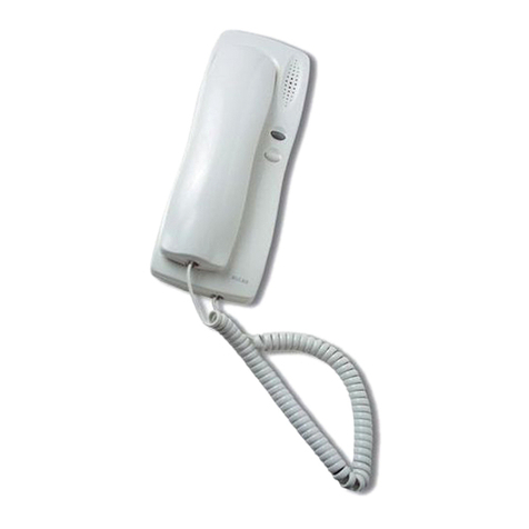
INSTALACIÓN DE 1 MONITOR CON 1 TELÉFONO EN PARALELO
INSTALLATION OF 1 MONITOR AND 1 TELEPHONE IN PARALLEL
INSTALLATION DE 1 MONITEUR ET 1 TÉLÉPHONE EN PARALLÈLE
MVB-001
+
SCM-010
TES-001
17
5
2
5
COAX
VIDEOPORTERO ELECTRÓNICO - VIDEODOOR ENTRY SYSTEMS - VIDÉOPORTIER ÉLECTRONIQUE
Ver instrucciones de ajuste
Refer to adjustment instructions
Consultez les instructions de réglage
R1
(75 W)
V1
M

INSTRUCCIONES DE INSTALACIÓN
INSTALLING INSTRUCTIONS
INSTRUCTIONS D'INSTALLATION
RECOMENDACIONES - RECOMMENDATIONS - RECOMMANDATIONS
A la hora de colocar la placa de calle, asegúrese que ni los rayos del sol ni fuentes de luz intensa incidan directamente sobre la
telecámara, evitando así efectos no deseados en la visualización de la imagen (efecto contraluz) y manteniendo la vida útil del equipo.
When installing the entrance panel make sure that the sunrays or intense light sources do not fall directly on the video unit, avoiding
nonwhished effects in picture display (backlight effect) and same way keeping the operational life of the equipment.
Lorsque vous installerez la plaque de rue, assurez-vous bien que les rayons solaires ou une autre source de lumière intense ne coïncide
pas directement sur la caméra, vous evíterez ainsi les problémes de visualisation (effet contre jour,...) et préserverait la vie du matériel.
CAJA DE EMPOTRAR - FLUSH MOUNTED BOX - BOÎTIER ENCASTRABLE
Rompa el tabique de las aberturas que requiera
para pasar los cables.
Break off the perforated holes that you need to
pass the cables through.
Cassez la cloison des ouvertures nécessaires pour
faire passer les câbles.
1
Coloque la caja de empotrar de modo que la
parte superior quede a una altura de 1,7 m.
Place the flush-mounted box in position so that
the top is 1.7 m. high.
Placez le boîtier encastrable de telle sorte que la
partie supérieure soit placée à une hauteur de
1,7 m.
2
1,7 m
Levante, haciendo palanca, la pestaña del tarjetero
y coloque la etiqueta identificadora de cada
pulsador.
Lever open the cover of the card-holder and insert
the card that identifies the pushbutton
Levez la languette du panneau d'étiquettes en
faisant levier, et placez l'étiquette d'identification
correspondant à chaque bouton-poussoir.
1
PLACA DE CALLE - ENTRANCE PANEL - PLAQUE DE RUE
18
VIDEOPORTERO ELECTRÓNICO - VIDEODOOR ENTRY SYSTEMS - VIDÉOPORTIER ÉLECTRONIQUE
19
Extraiga los tapones y las bisagras de la caja de
empotrar. Extraiga las dos bisagras que requiera
según quiera abrir la placa hacia la derecha, la
izquierda o hacia abajo.
Remove the caps and the fixing pins from the
flush-mounted box. Choose the two fixing pins
you want to hinge the panel on to, so that it opens
either to the right or to the left or downwards.
Retirez les bouchons et les axes de fixation du
boîtier encastrable. Enlevez les deux axes requis
suivant si vous voulez ouvrir la plaque vers la
droite, vers la gauche ou bien vers le bas.
Realice las conexiones eléctricas. Consulte los
esquemas de cableado.
4
Make the electrical connections. See wired
diagrams.
Réalisez les connexions électriques. Voir schémas
de cablage.
ALIMENTADOR - POWER SUPPLY - ALIMENTATION
For mounting it on a wall, fix the power supply
with the screws that have been supplied.
Pour le montage mural, fixez l'alimentation à
l'aide des vis fournies.
Para montaje mural, fíje el alimentador con los
tornillos suministrados.
1
Place the rings of the panel over the extracted
fixing pins. The unused pins should be placed in
their slots.
Introduzca las anillas de la placa sobre los
bisagras. Introduzca completamente en sus ranuras
las bisagras no utilizadas.
Introduisez les anneaux de la plaque sur les axes
de fixation retirés. Introduisez complètement dans
leurs rainures les axes non utilisés.
3
2
VIDEOPORTERO ELECTRÓNICO - VIDEODOOR ENTRY SYSTEMS - VIDÉOPORTIER ÉLECTRONIQUE
20
Montaje en carril DIN.
Mounting on a DIN rail.
Montage sur rail DIN.
2
Realice las conexiones del alimentador con los
elementos que conforman el portero según se
indica en los esquemas de las instrucciones de
conexión.
Connect up the power supply with the elements
that make up the door entry system as shown in
the diagrams in the connection instructions.
Branchez l'alimentation avec les éléments qui
composent le système du portier comme illustré
dans les schémas des instructions de branchement.
3
Corte las aberturas pretroqueladas que necesite
del cubrebornas. Fíjelo al alimentador utilizando
los tornillos de sujeción.
Cassez les trous prédécoupés requis pour le couvre-
borne. Fixez le couvre-borne sur l'alimentation
en utilisant les vis de fixation fournies.
Cut the required perforated openings of the
terminal cover. Fix it to the power supply unit
using the fixing screws.
4
Si necesita desmontar el alimentador de un carril
DIN, desplace ligeramente la pestaña de sujeción
hacia abajo (1). Separe la parte inferior del
alimentador del carril DIN (2).
5
If you need to dismount the power supply unit
from a DIN rail, lightly press the fixing tab
downwards (1). Separate the lower part of the
power supply unit from the DIN rain (2).
Si vous avez besoin de démonter l'alimentation
du rail DIN, déplacer légèrement le clips de fixation
vers le bas (1) Séparer la partie inférieure de
l'alimentation du rail DIN (2).
VIDEOPORTERO ELECTRÓNICO - VIDEODOOR ENTRY SYSTEMS - VIDÉOPORTIER ÉLECTRONIQUE
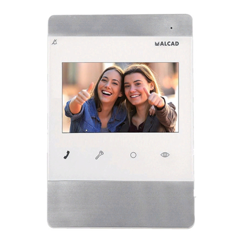
Table of contents
Other Alcad Intercom System manuals

Alcad
Alcad 972 Series User manual

Alcad
Alcad USOA User manual

Alcad
Alcad GRF-204 User manual

Alcad
Alcad TEL-001 User manual

Alcad
Alcad TED-001 User manual

Alcad
Alcad CIC-231 User manual

Alcad
Alcad 963 Series User manual

Alcad
Alcad TED-001 User manual

Alcad
Alcad MVB-003 User manual

Alcad
Alcad TCB-010 User manual

Alcad
Alcad GRF-400 User manual

Alcad
Alcad 980 Series User manual

Alcad
Alcad 972 Series User manual

Alcad
Alcad GRF-202 User manual

Alcad
Alcad TEL-002 User manual

Alcad
Alcad MVC-141 User manual

Alcad
Alcad 980 Series User manual

Alcad
Alcad 960 Series User manual

Alcad
Alcad 980 Series User manual

Alcad
Alcad KVS-56121 User manual