Aristel DV-38 User manual

D
V
-38
S
y
stem Installation Manual
A
Ar
ri
is
st
te
el
l
N
Ne
et
tw
wo
or
rk
ks
s
DV38
INSTALLATION GUIDE
Version number 1.1 issued November 2004
Aristel Networks Pty Ltd
Unit 3A, 100 Station Street
Nunawading VIC 3161
Telephone: 03 9837 2300
Facsimile: 03 9872 4433
1
Arista Systems Corporation

S
y
stem Installation Manual D
V
-38
INTRODUCTION .............................................................................................4
GENERAL DESCRIPTION..............................................................................5
SYTEM CONFIGURATION..............................................................................7
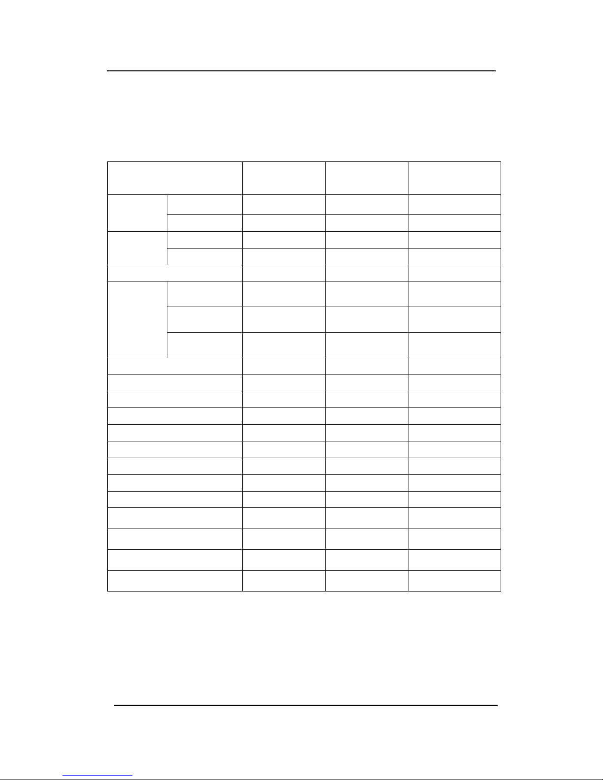
SYSTEM CAPACITYAND SPECIFICATIONS ....................................................................7
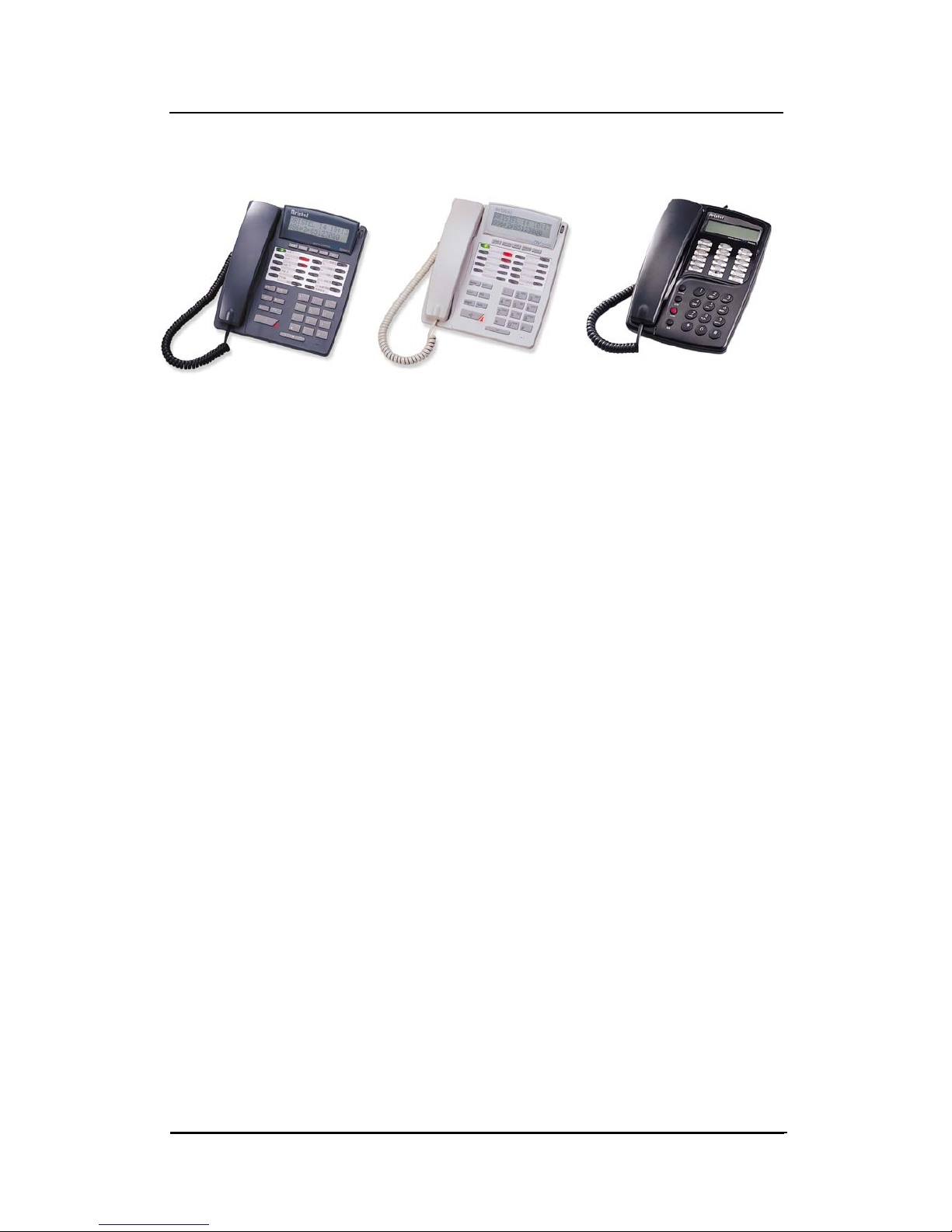
KEYTELEPHONE SPECIFICATION......................................................................8
SYSTEM MODELDESCRIPTION..........................................................................9
FEATURE LIST.......................................................................................................10
ENVIROMENTAL REQUIREMENT...............................................................12
EQUIPMENT REQUIREMENT......................................................................13
POWER SUPPLY AND KSU INSTALLATION...............................................14
PCB AND CABINET LAYOUT ......................................................................15
D1MBUB (MOTHER BOARD UNIT)..........................................................................16
D1PWUA(POWER BOARD UNIT).......................................................................18
D1TKUC (TRUNK UNIT, 4TRUNK PORTS) .......................................................19
D1DTKA(ISDN BRI TRUNK UNIT) ........................................................................20
D1DLUB (DIGITAL KEY STATION UNIT,8KEY STATION PORTS) ..............................22
D1STUB (ANALOG KEY STATION UNIT,8KEY STATION PORTS)..............................23
D1SLCB (SINGLE LINE STATION CARD,2SLT STATION PORTS) ..............................24
D1RSCA(RS232 CARD,2400BPS SERIAL RS232 PORT) .........................................25
D1VSCA/B (VOICE SERVICE CARD,2VOICE CHANNEL).........................................28
D1MFCA(MULTI FUNCTION CARD,2SENSOR +2RELAYS +2DOOR PHONES)......29
D1MDCA(METERING PULSE CARD) .......................................................................30
D1RPCA(REMOTE PROGRAMMING CARD,2400BPS STANDARD MODEM)...............32
D1VMCA(VOICE MAIL CARD) ...............................................................................33
D1VMEA(VOICE MAIL EXPANSION CARD).............................................................34
D1VMFA(EXPANSION FLASH MEMORY).................................................................35
INSTALLATION AND WIRING ......................................................................36
AC POWERAND DC BATTERYBACK-UPINSTALLATION............................36
D1MBUB JUMPER SETTING ...............................................................................38
POTS CO LINE WIRING FOR D1TKUC...............................................................39
D1CIDCAND D1MDCAINSTALLATION.............................................................40
DIGITAL KEYPHONE WIRING FOR D1DLUB .............................................................41
2Arista Systems Corporation

D
V
-38
S
y
stem Installation Manual
ANALOGUE KEYPHONE WIRING FOR D1STUB.........................................................42
50 PINS (25 PAIRS)MALE AMPHENOL CONNECTOR LAYOUT ....................................43
SINGLE LINE PHONE WIRING FOR D1SLCB.............................................................44
2-WIRES DOOR PHONE INSTALLATION......................................................................45
SENSOR INSTALLATION .............................................................................................46
DOOR SWITCH INSTALLATION ...................................................................................47
EXTERNAL MUSIC SOURCE INSTALLATION................................................................48
RS232(SERIALPRINTER OR PC)INSTALLATION..............................................49
3
Arista Systems Corporation
SPECIFICATIONS ARE SUBJECT TO CHANGE WITHOUT NOTICE

S
y
stem Installation Manual D
V
-38
INTRODUCTION
This manual provides detailed procedures to install your new ARISTEL DV-38
Digital Key Telephone System. Please read this entire section before
proceeding with the actual installation.
The National Electrical Code (NEC) requires the local telephone company
(Telecom) to provide the primary protection devices for the telephone lines
terminating at the customer’s site. Make sure that a primary protection
device has indeed been installed by the Telecom. If no such device is
present, notify the Telecom before installing yourAristel system.
4Arista Systems Corporation

D
V
-38
S
y
stem Installation Manual
GENERAL DESCRIPTION
Aristel DV-38 Fully Digital Key Phone System is an intelligent Telecom device and
based on state of the art advanced technology. This system uses digital circuitry
employing PCM, TDM, 2B+D, etc. The multi-function digital key phone has very
flexible programming functions. The users can simply operate the DSS keys to
activate the applications as they require. The new built-in Voice Mail not only
provides standard voice mail functions but also has the Intelligent Recording
function – to record message during conversation. The Windows version
Customer Manager System (CMS) is fully integrated into the system to make
customer management easier and more efficient.
Aristel DV-38 Intelligent Digital Key Telephone System, has the listed capacities:-
trunk card (basic 4 lines per card, maximum 3 cards = 12 ports) and 8~26 extension
ports. It can also be equipped with the following system peripherals: SMDR
interface, Door Phone Interface, Multi-Function Sensor Interface, Multi-Function
Relay, Remote Programming Interface, External Music Interface, External paging
interface, Voice Mail and Auto Attendant Interface, DECT Interface, ADSL/ISDN…etc.
Aristel DV-38 Digital Intelligent Key Telephone System uses modular PCB
construction. External-Line, Internal-Line and peripherals of the main system are
completely independent PCBs. All functions are able to be programmed to Macro
keys, enabling complex functions to covert into single-keypad operation. This is an
excellent option for the new digital age; Aristel DV-38 is the best partner to lead you
into the diverse broadband world of telecommunications
5
Arista Systems Corporation

S
y
stem Installation Manual D
V
-38
Aristel DV-38 Digital Intelligent Key Phone System
Multiple Processors.
Time Division Multiplexing.
Unique ARISTELASIC Chip “A-SERIES”
6Arista Systems Corporation

D
V
-38
S
y
stem Installation Manual
SYSTEM CONFIGURATION
System Capacity and Specifications
DV-38 Basic Capacity
Expandable
Capacity Max. Capacity
POTS 4 8 12
CO Line ISDN (BRI) 0 0 ~ 6 6
Digital 8/0 16/0 24/0
Key phone Analog 0/8 0/16 0/24
Single Line Phone 0 2 2
Auto Attendant 0 4/0 4/0
Voice Mail 0 0/4 0/4
Voice
Service
interface Recording
Extension 0 26 26
Door Phone interface 0 2 2
Relay Switches 0 2 2
Sensor 0 2 2
Fax Monitor 1 2 3
RS232 For SMDR 0 1 1
Remote Programming 0 1 1
UPS interface 1 0 1
Speed Dial 1000 sets 0 1000 sets
Caller ID card 0 12 12
Power Failure Transfer Phone 1 2 3
External Music 1 0 1
External Paging 0 1 1
DSS64 consoles N/A N/A 4
7
Arista Systems Corporation

S
y
stem Installation Manual D
V
-38
KEY TELEPHONE SPECIFICATION
DIGITAL KEY TELEPHONE
Key Phone Model DKP30 DKP31 DKP32 DKP33 DKP50 DKP51 DKP52 DKP53
DSS Function Key 12 Keys 12 Keys 12 Keys 12 Keys 25 Keys 25 Keys 25 Keys 25 Keys
2 * 16 digits LCD
Display …9…9…9…9
Back-Light LCD Display ……………Option …Option
Hands-Free Dialing 99999999
Direct intercom 99999999
Outgoing Call
Hands-Free ……99……99
Internal/External
Direct Dial 99999999
Photo Interrupt
Hook Switch 99999999
Digital Volume Control 8 Levels 8 Levels 8 Levels 8 Levels 8 Levels 8 Levels 8 Levels 8 Levels
OHCA Function ……99……99
One Touch Paging 99999999
Last Number Redial 99999999
Name Speed Dial …9…9…9…9
Calculator ……………9…9
Individual Speed Dial 99999999
Difference Ringing
Frequencies 99999999
Dual Color Tri Status
LED 8 keys 8 keys 8 keys 8 keys 16 keys 16 keys 16 keys 16 keys
One Digit Auto Answer 99999999
Incoming LED
Indication 99999999
Remarks: Postfix W= White Color, C= Dark Grey Color, B= Back-Light LCD Display
8Arista Systems Corporation

D
V
-38
S
y
stem Installation Manual
SYSTEM MODEL DESCRIPTION
Model Description Remark
D1-408DK Main Service Unit - Consisting of Plastic Cabinet + D1MBUB +
D1PWUA + D1TKUC + D1DLUB Standard Shipment
D1CBMA Main Service Unit - Consisting of (Plastic Cabinet + D1MBUB +
D1PWUA) Standard Shipment
D1MBUB Mother Board Unit Spare Part
D1PWUA Power Unit Spare Part
D1TKUC Trunk Unit - Consisting of 4 PSTN ports with Polarity Reverse, one
Fax port Connector、one PFT port connector and Interface for
D1MDCA and D1CIDA Connections. Expansion Card
D1DTKA ISDN Trunk Card - Consisting of 2 BRI S/T interface Optional Card
D1DLUB Digital Key Station Unit – Consisting of 8 Digital Key Station ports Expansion Card
D1STUB Key Station Unit – Consisting of 8Analog Key Station ports Expansion Card
D1SLCB Single Line Station Card – Consisting of 2 Single Line Station Ports Expansion Card
D1RSCC RS232 Card – Providing 1 RS232 port and working for SMDR Optional Card
D1VSCA Voice Service Card – Consisting of 2 Voice Channels (60 sec. per
channel) for Auto Attendant applications Optional Card
D1VSCB Voice Service Expansion Card - Additional 2 Voice Channels (60
sec. per channel) for Auto Attendant applications Optional Card
D1MFCA Multi Function Card –
(2 Doors + 2 Relays + 2 Sensors + 1 External Paging) Optional Card
D1MDCA Meter Pulse Detection Card - 12KHz/16KHz Meter Pulse Detection Optional Card
D1CIDC FSK/DTMF CLI Interface - One Channel of POTS Caller Number
Identification Card Expansion Card
D1RPCA Remote Programming Card - Providing 1 standard modem port
2400 bps) and working for Remote maintenance Optional Card
D1VMCA Built-in Voice Mail Card - 2 ports of Voice Mail with 6.5 hours
recording time Optional Card
D1VMEA Voice Mail Expansion Card - one port of Voice Mail Optional Card
D1VMFA Expansion Flash Memory - Software control with 4 hours store
memory Optional Card
WP5007 25-Pair Amphenol Cable – (for Station Wiring Connection) Optional Required
9
Arista Systems Corporation

S
y
stem Installation Manual D
V
-38
FEATURE LIST
System Features List
z3 Parties Conference
z5 Different Trunk Access Codes
zAccount Code
Auto Attendant
zAuto Accessing Trunk
zAutomatic Answer
zAuto Pick Up
Automatic Call Distribution (ACD)
Automatic Transfer
Baby Listening
zBe/Internal/External/Group Paging
Built-in Voice Mail
Caller’s Number Identification
(Caller ID)
zCall Limit Time Duration
zCall Park
zCall Split
zData Monitor
zConsole Grouping
zDate/Time Setting
zDay Time Schedule
zDay/Night Service
zDirect Intercom Dialing
Direct Inward Dialing (DID)
zDirect Inward Station Access (DISA)
Door Phone Connection
Door Switch Control
zEMI Filter
Environment Monitor
zExternal Call Forward (ECF)
zFax Monitor
zFlexible Function Key Assignment
zForced Account Code
zHeadset Function
zHot Line
Hotel/Motel Function w/o PC
zIllegal Outgoing Protection
zIntercom Busy Reminder
zIncoming Hunting
zIncoming Paging
zIntercom Hunting
zInternal/External Music Source
zInternal/External Paging
ISDN Compatible
zKey Station Short Protection
zLCR (Least Cost Routing)
zLightning Protection
zManual Line
zMessage Waiting
Metering Pulse Detection
zName Speed Dialing (Phone Book)
zOne Touch Operation
zPolarity Reverse
zPower Failure Telephone
zPrivate Line
zProgramming Help List
Remote Programming
Remote Relay Control
Security/Fire Alarm System
zSingle Digit Dialing
zSLT Hold Message/Function
Capability
Station Loud Bell
SOS
Station Message Details Report
(SMDR)
zSystem Alarm
zToll Restriction
zTone/Pulse Dialing
zTrunk Grouping
Trunk Loud Bell
zTrunk Queuing
zUnsupervised Conference
Means the optional function.
10 Arista Systems Corporation

D
V
-38
S
y
stem Installation Manual
Station Features List
z16×2 Dot-Matrix LCD Display
z5 Different NumbersAuto Redial
z9 Different Ringing Frequencies on
Key Station
zAdjustable LCDAngle (DKP50)
Back Light LCD Display
Calculator Function (Display Phone)
zCall Forward/Call Follow Me
zCall Forward To Individual Speed
Dial
zCall Pick Up
zCall Transfer
zCamp On
zConference
zDay/Night Service Indication
zDigital Volume Control (8 Levels)
zDo Not Disturb
zDual-Color/Tri-Status BLF Indication
zErgonomics Receiver Handset
zHandsfree Dialing
Handsfree Conversation
zHold/Exclusive Hold
zLast Number Redial
zMacro Key Setting
zMessage Text
zMonitor
Off Hook CallAnnouncement
(OHCA)
zOverride
zPage/Be Paged
zStation Lock/Unlock
zStation Name Setting
zStation Operation Help List
zStation Lock/Unlock
zStation Name Setting
zStation Operation Help List
means the optional function.
11
Arista Systems Corporation

S
y
stem Installation Manual D
V
-38
ENVIROMENTAL REQUIREMENT
zThe Key System Unit (KSU) should be installed at a clean, dry and secure
location accessible only by authorized personnel. The location must have
adequate ventilation and a temperature range between 0 ~ 45o C with a 10
~ 90% non-condensing relative humidity.
zThe installation site should have sufficient room to mount the KSU along
with the necessary connecting blocks and ancillary equipment on a wall.
The installation site should not be in areas subject to static electricity (e.g.
Dry copiers), or vibration (e.g. Heavy machinery).
zA dedicated earthed power outlet for the KSU (either 240VAC/50Hz or
110VAC/60Hz) and a 10 Amp circuit are required. An integral earth is
required in the AC power cord. If a music source or optional external
paging equipment is installed, it must be connected to an AC circuit
separate from the KSU’s dedicated AC line. ONLY THE KSU’S POWER
SUPPLY SHOULD BE CONNECTED TO THE DEDICATED AC OUTLET.
12 Arista Systems Corporation

D
V
-38
S
y
stem Installation Manual
EQUIPMENT REQUIREMENT
Prior to installation, carefully inspect all packages for evidence of damage.
Compare the equipment received against equipment ordered to ensure that
ALL components have been received.
The following materials are required (not provided) for installation:
zExterior grade plywood back board for the KSU.
z1 Male-Tail per extension board for Station wiring.
zAppropriate mounting hardware.
13
Arista Systems Corporation

S
y
stem Installation Manual D
V
-38
POWER SUPPLY AND KSU INSTALLATION
zAttach the plywood back board to the selected location with the
appropriate fasteners.
zA surge protector should be installed at the dedicated AC outlet.
zConnect Male-Tail, and connect the plug to each station board for station
wiring; also connect the wire to the RJ-11 for connector on each trunk card
for the CO lines wiring.
zPlug in the power cord of the power supply to an AC Power Outlet and
then turn on the power of the system.
14 Arista Systems Corporation

D
V
-38
S
y
stem Installation Manual
PCB AND CABINET LAYOUT
SYSTEM INTER-CIRCUIT LAYOUT
D1RSC
D1MFC
D1PWU
D1SLC
D1VSCA
D1VMCA
D1MBUB
D1TKUC
D1DTKA
D1DLUB
D1STUB
D1RPCA
Figure 1. System Inter-Circuit Layout
1. AC Power Inlet.
2. AC Power Switch.
3. Power Indicator(LED Type).
4. DC Power Switch.
5. For D1SLCB Earth Grounding.
6. 2-Wire Female Connector.(For External Battery Box Connection).
7. Earth Ground(For Lightning Protection Ground).
8. Wiring Area and the Cable Outlet.
9. RS232(Female DB9)for the connection to the D1RSCC.
15
Arista Systems Corporation

S
y
stem Installation Manual D
V
-38
D1MBUB (Mother Board Unit)
Product: DV-38 Mother Board Unit
Item: D1MBUB
Size: 310 mm x 130 mm
Function:
1. The motherboard control entire system functions and audio switching.
2. Motherboard supports External Music Source Input Terminal.
3. System programming Auto-Protection by Li Battery.
The installation site
of D1MBUB
9
10
17
1
2
4
3
8
11
12
13
14
5
6
7 15
16
16 Arista Systems Corporation

D
V
-38
S
y
stem Installation Manual
1. POWER: 6 pins Wafer Connector to connect with D1PWUAby 6 wires cable
[HD-3903-10, VH Type]
2. VSC: 20Px2 Wafer Connector for D1VMCAor D1VSCA connections.
3. EPROM: Flash Memory EPROM “MX28F2000” which stored the system software.
4. CPU: Intel 80188 Processor.
5. RPC: 20Px2 Wafer Connector Either D1RPCAor D1RSCB connections.
6. BAT: “3 VDC, 180mA/H” Li-Battery to back-up system programming data during
AC power failure.
7. RSC: 10Px2 Wafer Connector for D1RSCC connection.
8. SVR: Variable Resistor to adjust the volume of the Internal Melody Source that use
for [BGM] and [MOH] applications.
9. MFC: 13Px2 Wafer Connector for D1MFCA connection.
10. SLC: 13Px2 Wafer Connector for D1SLCB connection.
11. STA1~3: 30Px2 Header Connector for both D1DULB and D1STUB connection.
12. ASIC: Aristel proprietary ASIC.
13. LCD: Additional LCD connector for engineering system maintenance.
14. JP1: 3 Pins Wafer Jumper to turn ON/OFF Li battery power.
15. TKU1~3: 25Px2 Header Connector for both D1TKUC and D1DTKAconnection.
16. JP2: 3 Pins Wafer Jumper for Internal/External music selection.
17. EX-MUSIC: The input terminal for External Music Source connection.
17
Arista Systems Corporation

S
y
stem Installation Manual D
V
-38
D1PWUA (POWER BOARD UNIT)
Product: DV-38 POWER UNIT
Item: D1PWUA
Size: 270 mm x 95 mm
Function:
1. To supply entire system power.
2. The input AC Voltage ranges are AC110V~240V
1
5
3
4 8
6
7
2
3. Support 24V Battery Charger for external
Back-up Battery.
The installation site of
D1PWUA
Figure 3. D1PWUA (POWER UNIT)
1. LED501: Power Indicator.
2. SW101: AC Power Switch.
3. CN101: AC Power Inlet.
4. CN802: 4 PinsConnector. (Reserved for further Applications)
5. SW401: External backup battery Power Switch.
6. CN105: Earth Terminal for D1SLCB Grounding.
7. CN402: External Battery Connector; Left Side is (+), Right side is (-).
8. CN301 : 6 Pins Connector for D1MBUB connection.
18 Arista Systems Corporation

D
V
-38
S
y
stem Installation Manual
D1TKUC (TRUNK UNIT, 4 TRUNK PORTS)
Product: DV-38 TRUNK UNIT
Item: D1TKUC
Size: 162 mm x 122 mm
Function:
1. Support Polarity Reverse detection for each CO lines.
2. A maximum of 3 D1TKUC boards can be installed onto the DV-38 main frame.
4. Support either D1CIDC or D1MDCA connections on each CO line.
4 3
2
1
The installation site of
D1TKUC, D1DTKA
Figure 4. D1TKUC (TRUNK UNIT, 4 TRUNK PORTS)
1. CN1: 60-Wires rainbow Cable to connect to TKU1~3 positions where upon the D1MBUB.
2. CN3: The socket for both Power Failure standard Phone and FAX connections.
3. CN2: The RJ socket for POTS CO lines connections.
4. CH1~4B: Connectors for each CO lines to interface either D1CIDC or D1MDCA.
19
Arista Systems Corporation

S
y
stem Installation Manual D
V
-38
D1DTKA (ISDN BRI Trunk Unit)
Product: DV-38 ISDN TRUNK UNIT
Item: D1DTKA (ISDN BRI CARD)
Size: 162 mm x 122 mm
Function
1. Supports 2 lines of 2B+D interface which support 4 voice channels.
2. The system provides 3 slots of ISDN Trunk Unit connector. (Maximum expansion
capability: 6 lines for 2B+D or 12 lines for Voice channel.)
7
6
5
Figure 5. D1DTKA (ISDN TRUNK UNIT, 2 BRI PORTS)
The installation site of
D1DTKA
3
2
1
4
1. Test Connector for engineer testing.
2. Test Connector for engineer testing.
3. Flat cable connect to D1MBUB.
4. RJ-45 connector to connect to ISDN BRI Line.
5. JP1 jumper for first line-line termination enable/disable. DO NOT ALTER
6. JP2 jumper for second line-line termination enable/disable. DO NOT ALTER
7. JP3 jumper for DTKAcard of TKU slot number. See table on next page.
20 Arista Systems Corporation
Other manuals for DV-38
1
Table of contents
Other Aristel Telephone manuals

Aristel
Aristel IPX-100 User manual

Aristel
Aristel AV SERIES User manual

Aristel
Aristel AV-8 User manual

Aristel
Aristel AV-8 User guide

Aristel
Aristel Genius X2 User manual

Aristel
Aristel Powerphone User manual

Aristel
Aristel AV SERIES User manual

Aristel
Aristel 50 Series User manual

Aristel
Aristel AV SERIES User manual

Aristel
Aristel AV-38 User manual