manuals.online logo
Brands
  1. Home
  2. •
  3. Brands
  4. •
  5. Assa Abloy
  6. •
  7. Door Lock
  8. •
  9. Assa Abloy Hes 5200 Series User manual

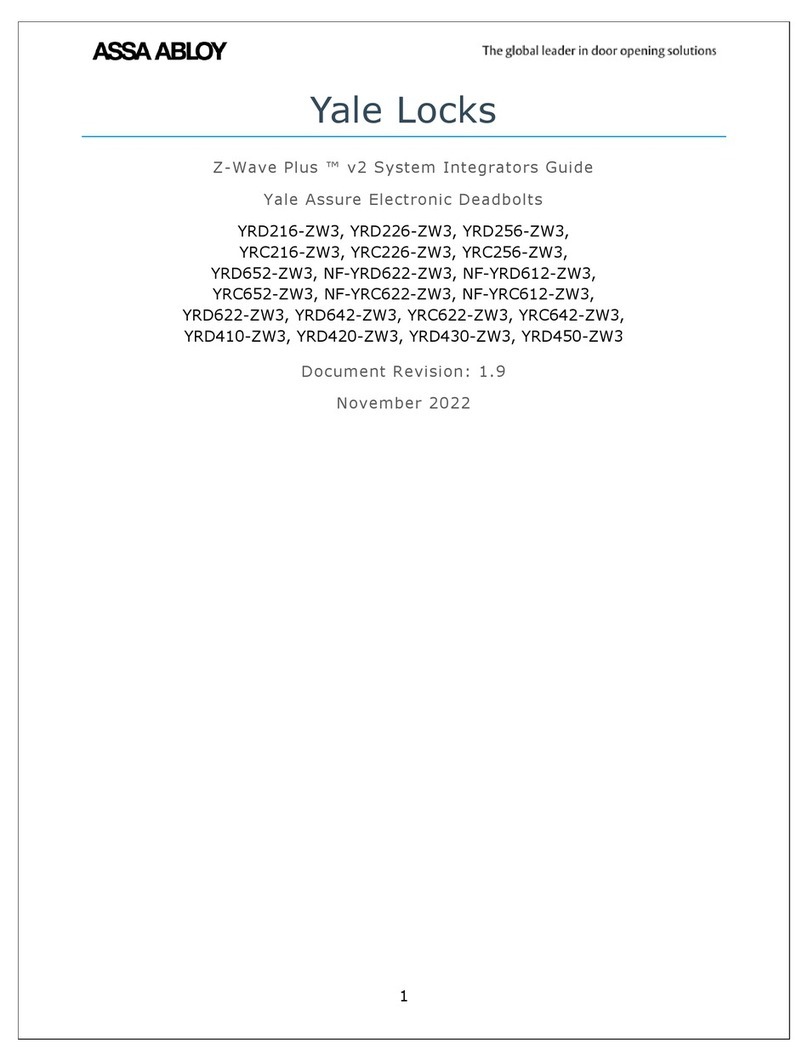
Assa Abloy Hes 5200 Series User manual

Installation Instructions
5200 Series Electric Strike
HES, Inc.
Phoenix, AZ
800-626-7590
www.hesinnovations.com
1
Electrical Specifications
Minimum Wire Gauge Requirements
(Based on Round Trip)
Solenoid Voltage
12 VDC 24 VDC
200 feet or less
200 – 300 feet
300 – 400 feet
18 gauge
16 gauge
14 gauge
20 gauge
18 gauge
16 gauge
3
ASSA ABLOY, the global leader
in door opening solutions
Product Components
12
5200 Electric Strike Body Trim Enhancer 12-Volt and 24-Volt Pigtails
Electrical Ratings for Solenoid
Continuous Duty 12 VDC
50
.24
24 VDC
200
.12
Resistance in Ohms
Amps
Solenoids are rated at +/- 10% indicated value.
*10% maximum duty cycle (2 minutes maximum on time)
Indoor use only
4
Cutout Templates for Frame Preparation
© 2015, Hanchett Entry Systems, Inc., an ASSA ABLOY Group company.
3059006.002 rev C
1
2
3
Diagram 1: Product Components
Intermittent Duty* 12–16 VAC
50
.24 – .32
24 VAC
200
.12
Resistance in Ohms
Amps
501 Faceplate Option (4-7/8” x 1-1/4”), Square Corners and Flat Faceplate
Used with cylindrical locksets in ANSI metal jambs
501A Faceplate Option (4-7/8” x 1-1/4”), Radius Corners and Flat Faceplate
Used with cylindrical locksets or spring latches in aluminum frames
[mm]
Inches
1 -1/4"
[31.8]
4 -7/8"
[124]
3 -3/8"
[85.7]
13/16"
[20.6]
3/32"
[2.3]
4 -7/8"
[124]
4 -1/8"
[104.8] 1 -7/16"
[36.6]
1 -1/4"
[31.8]
R 1/8"
[3]
3 -3/8"
[85.7]
1 -1/4"
[31.8]
4 -7/8"
[124]
13/16"
[20.6]
[2.3]
3/32"
[mm]
Inches
1 -1/4"
[31.8]
4 -7/8"
[124]
4 -1/8"
[104.8] 1 -7/16"
[36.6]
[mm]
Inches
3-3/8"
[85.7]
13/16"
[20.6]
3/32"
[2.3]
1 -7/16"
[36.5]
7-15/16"
[201.6] 1 -7/16"
[36.6]
7 -15/16"
[201.6]
7 -7/16"
[189]
1 -7/16"
[36.6]
R 3/16"
[4.1]
502 Faceplate Option (7-5/16” x 1-7/16”), Radius Corners and Flat Faceplate
Used with cylindrical locksets or spring latches in aluminum frames
[mm]
Inches
1 -1/4"
[36.5]
3 -3/8"
[85.7] 6 -7/8"
[174.3]
13/16"
[20.6]
3/32"
[2.3]
6 -7/8"
[174.3] 6 -1/8"
[155.6]
1 -1/4"
[31.8]
1 -7/16"
[36.6]
R 3/16"
[4.1]
503 Faceplate Option (6-7/8” x 1-1/4”), Radius Corners and Flat Faceplate
Used with cylindrical locksets or spring latches in aluminum frames
[mm]
Inches
10"
[254]
1 -3/8"
[34.9]
3 -3/8"
[85.7]
13/16"
[20.6]
3/32"
[2.3]
1 -3/8"
[34.9]
10"
[254]
8 -1/2"
[215.6] 8 -1/2"
[215.6]
1 -7/16"
[36.6]
1 -3/8"
[34.9]
R 1/8"
[4]
504 Faceplate Option (10” x 1-3/8”), Radius Corners and Flat Faceplate
Used with cylindrical locksets; four-point mounting for wood installations
NOTE: The 5200 has an in-frame horizontal adjustment range of about 1/4” (6.4 mm) to allow adjustment of the electric strike in the frame
opening to accomodate for the horizontal position of the latchbolt after the strike has been installed. The “Adjusting the Horizontal”
section provides steps for this adjustment.
2
Installation
3
Installation (continued)
LBM Wiring
White
Orange Normally Open
Green Normally Closed
Common
Normally Open
Yellow Normally Closed
DIAGRAM 5: CYLINDRICAL LOCKSETS
LBSM Wiring
Brown
Blue Normally Open
Yellow Normally Closed
Common
Note 1: The 5200 series Electric Strikes are
pre-set for FAIL SECURE OPERATION.
Note 2: There are two #2-56 screws located
on the back of the strike for coverting
the operation mode.
10. To convert from FAIL SECURE OPERATION
to FAIL SAFE OPERATION, LOOSEN the two
#2-56 screws located on the back of the
strike, but DO NOT REMOVE them.
11. MOVE the Selector Stop Pins to the FAIL
SAFE OPERATION position as pictured in
Diagram 5.
12. TIGHTEN the two #2-56 screws to secure
the strike in FAIL SAFE OPERATION.
13. VERIFY the 5200 is now in FAIL SAFE
OPERATION.
14. IF the 5200 still operates as FAIL SECURE,
THEN ENSURE the #2-56 screws are fully
seated and tightened.
Diagram 5: FAIL SAFE OPERATION Mode Setting
Brown
Blue
Yellow
White
Orange
Green
Converting the Operation Mode
Diagram 3: Latchbolt Monitor Diagram 4: Latchbolt Strike Monitor
Verifying the Operation Mode
15. TURN the horizontal adjustment screws slowly to
adjust the strike in-frame, as shown in Diagram 6.
16. DO NOT REMOVE the screws or ROTATE them more
than 3 full turns.
17. TIGHTEN the screws securely once the strike has
been adjusted to allow the K-Nut teeth to dig into
the strike housing and prevent slippage during use.
Adjusting the Horizontal
Diagram 6: Horizontal Adjustment
K-NUT
b
Horizontal
Adjustment
Screws
Note: For 12 VDC, the Plug In Connector (pigtail)
marked “12 VDC” should be used; for 24 VDC,
the pigtail marked “24 VDC should be used.
1. SELECT the appropriate pigtail that matches system
power and electrically CONNECT as illustrated in
Diagram 2.
2. If no connector is present, CONFIGURE the wires as
illustrated in Diagram 2.
3. If using the Latchbolt Monitor (LBM) or Latchbolt
Strike Monitor (LBSM), REFER to Diagrams 3 and 4
on Page 3 to complete wiring.
Note: The 5200 ships in FAIL SECURE OPERATION
mode.
4. USE Diagrams 5 and 6 on Page 3 as a guide to
convert 5200 to FAIL SAFE OPERATION, if needed.
5. ATTACH the appropriate faceplate.
CAUTION!
Before connecting any device at the installation site, verify input voltage using a multimeter.
Many power supplies and low voltage transformers operate at higher levels than listed. Any input voltage exceeding
10% of the solenoid rating may cause severe damage to the unit and will void the warranty.
6. PREPARE the frame using the appropriate template
for the faceplate (see Page 4).
RED
RED/GREEN
BLACK
VIOLET
RED
BLACK
VIOLET
RED/GREEN
IF CONNECTOR IS MISSING
(+ 12 VDC)
(-NEG)
(+ 24 VDC)
(-NEG)
or
Electric
Strike
Electric
Strike
CONNECT
TOGETHER
CONNECT
TOGETHER
CONNECT
TOGETHER
7. Electrically CONNECT the wires from the power
source to the 5200.
8. INSTALL the 5200 in the jamb cutout.
9. IF horizontal adjustment is needed,
THEN GO TO the “Adjusting the Horizontal”
section (see Page 3).
Preparing the Strike
Finishing the Installation
Preparing the Frame
Diagram 2: 12V to 24V Conversion
3
Installation (continued)
LBM Wiring
White
Orange Normally Open
Green Normally Closed
Common
LBSM Wiring
Brown
Blue
Common
Note 1: The 5200 series Electric Strikes are
pre-set for FAIL SECURE OPERATION.
Note 2: There are two #2-56 screws located
on the back of the strike for coverting
the operation mode.
10. To convert from FAIL SECURE OPERATION
to FAIL SAFE OPERATION, LOOSEN the two
#2-56 screws located on the back of the
strike, but DO NOT REMOVE them.
11. MOVE the Selector Stop Pins to the FAIL
SAFE OPERATION position as pictured in
Diagram 5.
12. TIGHTEN the two #2-56 screws to secure
the strike in FAIL SAFE OPERATION.
13. VERIFY the 5200 is now in FAIL SAFE
OPERATION.
14. IF the 5200 still operates as FAIL SECURE,
THEN ENSURE the #2-56 screws are fully
seated and tightened.
Diagram 5: FAIL SAFE OPERATION Mode Setting
Brown
Blue
Yellow
White
Orange
Green
DI LOCKSETS
Converting the Operation Mode
Diagram 4: Latchbolt Strike Monitor
Verifying the Operation Mode
15. TURN the horizontal adjustment screws slowly to
adjust the strike in-frame, as shown in Diagram 6.
16. DO NOT REMOVE the screws or ROTATE them more
than 3 full turns.
17. TIGHTEN the screws securely once the strike has
been adjusted to allow the K-Nut teeth to dig into
the strike housing and prevent slippage during use.
Adjusting the Horizontal
Diagram 6: Horizontal Adjustment
K-NUT
b
Horizontal
Adjustment
Screws
Normally Closed
Normally Open
Yellow
Yellow
Diagram 3: Latchbolt Monitor
4
3059006.002 rev C
© 2015, Hanchett Entry Systems, Inc., an ASSA ABLOY Group company.
501 Faceplate Option (4-7/8” x 1-1/4”), Square Corners and Flat Faceplate
Used with cylindrical locksets in ANSI metal jambs
[mm]
501A Faceplate Option (4-7/8” x 1-1/4”), Radius Corners and Flat Faceplate
Used with cylindrical locksets or spring latches in aluminum frames
Inches
1 -1/4"
[31.8]
4 -7/8"
[124]
3 -3/8"
[85.7]
13/16"
[20.6]
3/32"
[2.3]
4 -7/8"
[124]
4 -1/8"
[104.8] 1 -7/16"
[36.6]
1 -1/4"
[31.8]
R 1/8"
[3]
3 -3/8"
[85.7]
1 -1/4"
[31.8]
4 -7/8"
[124]
13/16"
[20.6]
[2.3]
3/32"
[mm]
Inches
1 -1/4"
[31.8]
4 -7/8"
[124]
4 -1/8"
[104.8] 1 -7/16"
[36.6]
[mm]
Inches
3-3/8"
[85.7]
13/16"
[20.6]
3/32"
[2.3]
1 -7/16"
[36.5]
7-15/16"
[201.6] 1 -7/16"
[36.6]
7 -15/16"
[201.6]
7 -7/16"
[189]
1 -7/16"
[36.6]
R 3/16"
[4.1]
502 Faceplate Option (7-5/16” x 1-7/16”), Radius Corners and Flat Faceplate
Used with cylindrical locksets or spring latches in aluminum frames
[mm]
Inches
1 -1/4"
[36.5]
3 -3/8"
[85.7] 6 -7/8"
[174.3]
13/16"
[20.6]
3/32"
[2.3]
6 -7/8"
[174.3] 6 -1/8"
[155.6]
1 -1/4"
[31.8]
1 -7/16"
[36.6]
R 3/16"
[4.1]
503 Faceplate Option (6-7/8” x 1-1/4”), Radius Corners and Flat Faceplate
Used with cylindrical locksets or spring latches in aluminum frames
[mm]
Inches
10"
[254]
1 -3/8"
[34.9]
3 -3/8"
[85.7]
13/16"
[20.6]
3/32"
[2.3]
1 -3/8"
[34.9]
10"
[254]
8 -1/2"
[215.6] 8 -1/2"
[215.6]
1 -7/16"
[36.6]
1 -3/8"
[34.9]
R 1/8"
[4]
504 Faceplate Option (10” x 1-3/8”), Radius Corners and Flat Faceplate
Used with cylindrical locksets; four-point mounting for wood installations
Cutout Templates for Frame Preparation
NOTE: The 5200 has an in-frame horizontal adjustment range of about 1/4” (6.4 mm) to allow adjustment of the electric strike in the frame
opening to accomodate for the horizontal position of the latchbolt after the strike has been installed. The “Adjusting the Horizontal”
section provides steps for this adjustment.

This manual suits for next models

1

Other Assa Abloy Door Lock manuals

Assa Abloy Adams Rite 3000SE User manual

Assa Abloy

Assa Abloy Adams Rite 3000SE User manual

Assa Abloy Yale nexTouch Technical specifications

Assa Abloy

Assa Abloy Yale nexTouch Technical specifications

Assa Abloy Aptus Yale Doorman User manual

Assa Abloy

Assa Abloy Aptus Yale Doorman User manual

Assa Abloy Sargent 10X Line User manual

Assa Abloy

Assa Abloy Sargent 10X Line User manual

Assa Abloy Yale YMI70A User manual

Assa Abloy

Assa Abloy Yale YMI70A User manual

Assa Abloy Corbin Russwin ED5200N Series User manual

Assa Abloy

Assa Abloy Corbin Russwin ED5200N Series User manual

Assa Abloy Lockwood Onyx 9A1A2/5PBLK User manual

Assa Abloy

Assa Abloy Lockwood Onyx 9A1A2/5PBLK User manual

Assa Abloy Yale YDD724A User manual

Assa Abloy

Assa Abloy Yale YDD724A User manual

Assa Abloy effeff 843 User manual

Assa Abloy

Assa Abloy effeff 843 User manual

Assa Abloy Aperio C100 V3 User manual

Assa Abloy

Assa Abloy Aperio C100 V3 User manual

Assa Abloy CL33700 TCPWI1 User manual

Assa Abloy

Assa Abloy CL33700 TCPWI1 User manual

Assa Abloy Sargent PE8600 Series User manual

Assa Abloy

Assa Abloy Sargent PE8600 Series User manual

Assa Abloy effeff ANYKEY 496 User manual

Assa Abloy

Assa Abloy effeff ANYKEY 496 User manual

Assa Abloy Corbin Russwin ED8400 Series User manual

Assa Abloy

Assa Abloy Corbin Russwin ED8400 Series User manual

Assa Abloy Yale 446F User manual

Assa Abloy

Assa Abloy Yale 446F User manual

Assa Abloy Sargent 7300 Series User manual

Assa Abloy

Assa Abloy Sargent 7300 Series User manual

Assa Abloy ABLOY EL574 User manual

Assa Abloy

Assa Abloy ABLOY EL574 User manual

Assa Abloy Corbin Russwin ED5800 Series User manual

Assa Abloy

Assa Abloy Corbin Russwin ED5800 Series User manual

Assa Abloy SARGENT IN120 Wi-Fi Series User manual

Assa Abloy

Assa Abloy SARGENT IN120 Wi-Fi Series User manual

Assa Abloy UNILOCK LOXURY IX User manual

Assa Abloy

Assa Abloy UNILOCK LOXURY IX User manual

Assa Abloy Corbin Russwin SE LP10 Series User manual

Assa Abloy

Assa Abloy Corbin Russwin SE LP10 Series User manual

Assa Abloy HES 9400 Operating instructions

Assa Abloy

Assa Abloy HES 9400 Operating instructions

Assa Abloy TD0192 User manual

Assa Abloy

Assa Abloy TD0192 User manual

Assa Abloy Sargent 6-Line User manual

Assa Abloy

Assa Abloy Sargent 6-Line User manual

Popular Door Lock manuals by other brands

Alarm Lock T3e Series Addendum overview

Alarm Lock

Alarm Lock T3e Series Addendum overview

Allegion Schlage Control user guide

Allegion

Allegion Schlage Control user guide

CODELOCKS KL1000 G3 NetCode Programming and operating instructions

CODELOCKS

CODELOCKS KL1000 G3 NetCode Programming and operating instructions

danalock US-version quick guide

danalock

danalock US-version quick guide

iver IV007 Install instructions

iver

iver IV007 Install instructions

Rook Smart owner's manual

Rook

Rook Smart owner's manual

PORT SHIELD user manual

PORT

PORT SHIELD user manual

CAMDEN CX-EPD1289L installation instructions

CAMDEN

CAMDEN CX-EPD1289L installation instructions

Weiser 62879-002 installation guide

Weiser

Weiser 62879-002 installation guide

Kwikset 816 installation guide

Kwikset

Kwikset 816 installation guide

Kaba Confidant RFID Kit 2 installation guide

Kaba

Kaba Confidant RFID Kit 2 installation guide

Schlage CO-250 user guide

Schlage

Schlage CO-250 user guide

Kaba Simplex LP1000 Series manual

Kaba

Kaba Simplex LP1000 Series manual

Salto Neo M1 Series installation guide

Salto

Salto Neo M1 Series installation guide

BNB Solutions Everlock BDS312 user manual

BNB Solutions

BNB Solutions Everlock BDS312 user manual

Maco INSTINCT Important instructions for use

Maco

Maco INSTINCT Important instructions for use

Dormakaba Saffire LX-D installation guide

Dormakaba

Dormakaba Saffire LX-D installation guide

LOCKEY GCTB175 manual

LOCKEY

LOCKEY GCTB175 manual

manuals.online logo
manuals.online logoBrands
  • About & Mission
  • Contact us
  • Privacy Policy
  • Terms and Conditions

Copyright 2025 Manuals.Online. All Rights Reserved.