manuals.online logo
Brands
  1. Home
  2. •
  3. Brands
  4. •
  5. Assa Abloy
  6. •
  7. Door Lock
  8. •
  9. Assa Abloy RIXSON W0700 Series User manual

Assa Abloy RIXSON W0700 Series User manual

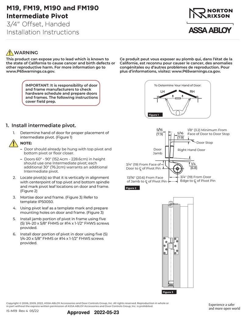
Installation Instructions
IS-W0700 (06-09)
W0700 Series Overhead Concealed Closer (Wood Door & Frame)
W0700 Series, Offset Hung Single Acting, Handed
PAGE 4
Rixson 866-474-9766 Technical Department
www.rixson.com
Rixson 866-474-9766 Technical Department
www.rixson.com
7. Adjust closing speed of door
To decrease speed turn valve clockwise. To increase
speed turn valve counter clockwise
To increase backcheck, turn valve clockwise, to decrease
backcheck turn valve counter clockwise
Notes:
1. Do not scale drawing.
2. Right hand shown.
3. For use on doors with a minimum 7/8" deep top mortise.
DO NOT use this template for head frames less than 2"x4-
1/2" wide. For 1-3/4" thick doors only.
4. .
5. All dimensions are in inches. Metric = 25.4 x inch.
No. 0198 mounting plate included. See template OC60210
C
L
TOP VIEW OF HEAD FRAME
HEAD FRAME INSTALLATION
1/4
1/2
1-9/16
1-9/16 1-3/8
1-3/8 45°
1/2
1/4
9/32 Dia. Mounting Holes
#14 x 2" Wood Screw
(4 Places)
3-23/32
Max Width
of Closer
1-23/641-39/64
1-39/64
17-1/2
2
C
L
SIDE VIEW OF HEAD FRAME
Spindle
31/64
1/2
1-7/64
From Bottom of
Head Jamb to Top
of Mounting Tabs
(Critical Dim.)
1-15/32 Max. Height
of Closer
UNDERSIDE OF HEAD FRAME
18-3/4
17-1/2
9-1/2
2-3/4
1-1/2
17-27/32
5/16 Dia. Holes for
10-24x5/16 FHMS
Cover Plate Screws
(6 Places)
1-7/16 Dia. Hole
In Cover Plate
1/2
Cover Plate Cutout
18-1/4 x 3-3/4
1-3/8
1-3/8
31/32
31/32
9/32 Dia. Holes for
Adjusting Valves
(2 Places)
2-1/4
C
L
1-23/64
2-1/4
From Pull Side
Of Head Frame
1-1/4
7/8 Min. Stop
Cutout
14-3/4 Length of Stop Cutout Removable stop by others.
Length to be width of head
frame between side jambs.
From Pull Side
of Head Frame
Critical Dim.
Door
Closer
1/16
Clearance
Door Hanging
Method
Closer
No.
Butt
Hinge
3/4 Offset Side
Jamb Pivot
4 x 4
4-1/2
x
4-1/2
W070090
W0700105
W070090
W0700105
W070090
W0700105
Max.
Degree
Dim.
"A"
86°
106°
88°
108°
93°
113°
7/8
7/8
7/8
1-5/8
DOOR INSTALLATION
C
L
#12 x 1-1/2" FHWS
(4 Places)
TOP VIEW OF DOOR
PUSH SIDE OF DOOR
4-1/2" OR WIDER
HEAD FRAME
1-1/8
9/16
17-1/8
13-5/8
6-5/8
10-1/8
7/8
7/8 9/16 17-7/8
5-7/8
1/16
Clearance
7/8
1/8 Clearance
7/8
1-5/16
1-1/16
Inside Dim.
Critical
1-7/8
Min. Inside
Dim.
Closer & Frame
C
LDoor & Rail
1-5/8
From Top of
Closer to Face
of Head Frame
C
L
Hinge
Edge of
Door
Cutout
In Hinge
Edge of
Door
A
ASSA ABLOY
RIXSON®
Adjust this valve to
increase or decrease
backcheck
Adjust this valve to
increase or decrease
speed of door
ASSA ABLOY
RIXSON®
Rixson® is a registered trademark of Yale Security Inc., an ASSA ABLOY Group company. Copyright© 2007, 2009, Yale Security Inc., an ASSA ABLOY Group company.
All rights reserved. Reproduction in whole or in part without the express written permission of Yale Security Inc. is prohibited.
PAGE 3
PAGE 2
Rixson 866-474-9766 Technical Department
www.rixson.com
Rixson 866-474-9766 Technical Department
www.rixson.com
1. Prepare head frame for 0198 Mounting Plate.
See 0198 Wood Mounting Plate template on
page 2.
Installation Instructions
2. Check 2-3/4" dimension from hinge jamb to 1/8"
dia. reference hole in Mounting Plate.
Check 1-1/8" dimension from under side of head
frame to the bottom of the mounting post.
3. Install Mounting Plate to head jamb using six (6)
12x1-1/2 FHWS.
Caution: End of Mounting Plate stamped "hinge"
to face hinge jamb of frame.
Closer Mounting Plate
Closer Body
Offset Arm
Included in package:
4. Install closer in head jamb by attaching closer
with (4) 1/4"-20 x 3/4" RHMS. Install cover plate.
5. Door Preparation
a. Prepare door for Arm Rail. See template
for necessary door prep.)
b. Install Arm Rail in door using (4) 12 x 1-
1/2 FHWS. Spring clip in rail must be
toward hinge edge of door.
c. Hang door. Pivots or butts not furnished
with overhead closer package.
Cover Plate
0198 Wood Mounting Plate
Rail
Side View of Head Frame
C
LCloser Spindle
1-1/8 (28.6) From Face
of Head Frame to Bottom
of Mounting Posts
Critical Dim.
2-3/4
(69.8)
1/8" (3.2) Dia. Ref.
Over Closer Spindle
18-1/4 (463.6) Cutout for Cover Plate
1/2
(12.7)
Underside View of Head Frame
3-3/4
(95.2)
Cutout
for Mounting
Plate
1"
(25.4)
C
L
Mounting
Plate
NOTES:
1. Do not scale drawing.
2. Right hand shown.
3. All dimensions given in inches (mm).
1-7/8
(47.6)
3-3/4
(95 )
Cutout for
Mounting Plate
.2
C
LDoor &
Mounting Plate
End View of Head Frame
Cutout for
Mounting
Plate
1-7/8
(47.6)
5/8
(15.9)
6-1/8
(155.6)
11-7/8
(301.6) 17-3/8
( )441.3
1"
(25.4)
#12 x 1-1/2 FHWS
(6 Places)
See Proper Closer
Template For Cutout
Length of Applied
Stop (by others)
Hinge
1-1/16
(27)
Critical
Inside Dim.
1-7/8
(47.6)
2-1/4 (57.2)
From Face of Head
Frame to Bottom of
Mounting Post
Critical Dim.
1-15/16
(49.2)
1-7/8
(47.6)
Min. Inside
Dim. of Stop
6. Installation of Arm
(Note: Close operating adjusting valve
controlling correct door swing. Leave backcheck
valve open.)
a. Using arm as wrench, it is IMPORTANT
that spindle of closer be turned to 90° or
into hold-open position.
b. Remove arm from spindle.
c. Open door to 90° and insert Slide Bar of
arm into Door Rail.
d. IMPORTANT: Slide arm directly back
toward hinge edge of door so that arm
can be attached to spindle. Slight
pressure will be required to override leaf
spring in rail. Do NOT remove Slide Bar
from rail.
e. Pull arm down and under closer spindle.
CAUTION: Care should be taken to avoid
distorting corner of door cutout.
f. Align arm hole and closer spindle. When
properly aligned, arm should readily slide
over closer spindle. DO NOT FORCE.
Door may require a slight movement back
and forth to aid in alignment of arm and
closer spindle. After arm is assembled
onto closer spindle tighten arm socket
head cap screw (5/16" - 18 x 1-1/4")
securely.
Arm in Open
Position
Head
Frame
Door
Slide Bar
Door Rail
Slide Arm
See Note
Mounting Plate
Closer
Cover Plate
Installation Instructions
IS-W0700 (06-09)
W0700 Series Overhead Concealed Closer (Wood Door & Frame)
W0700 Series, Offset Hung Single Acting, Handed
PAGE 4
Rixson 866-474-9766 Technical Department
www.rixson.com
Rixson 866-474-9766 Technical Department
www.rixson.com
7. Adjust closing speed of door
To decrease speed turn valve clockwise. To increase
speed turn valve counter clockwise
To increase backcheck, turn valve clockwise, to decrease
backcheck turn valve counter clockwise
Notes:
1. Do not scale drawing.
2. Right hand shown.
3. For use on doors with a minimum 7/8" deep top mortise.
DO NOT use this template for head frames less than 2"x4-
1/2" wide. For 1-3/4" thick doors only.
4. .
5. All dimensions are in inches. Metric = 25.4 x inch.
No. 0198 mounting plate included. See template OC60210
C
L
TOP VIEW OF HEAD FRAME
HEAD FRAME INSTALLATION
1/4
1/2
1-9/16
1-9/16 1-3/8
1-3/8 45°
1/2
1/4
9/32 Dia. Mounting Holes
#14 x 2" Wood Screw
(4 Places)
3-23/32
Max Width
of Closer
1-23/641-39/64
1-39/64
17-1/2
2
C
L
SIDE VIEW OF HEAD FRAME
Spindle
31/64
1/2
1-7/64
From Bottom of
Head Jamb to Top
of Mounting Tabs
(Critical Dim.)
1-15/32 Max. Height
of Closer
UNDERSIDE OF HEAD FRAME
18-3/4
17-1/2
9-1/2
2-3/4
1-1/2
17-27/32
5/16 Dia. Holes for
10-24x5/16 FHMS
Cover Plate Screws
(6 Places)
1-7/16 Dia. Hole
In Cover Plate
1/2
Cover Plate Cutout
18-1/4 x 3-3/4
1-3/8
1-3/8
31/32
31/32
9/32 Dia. Holes for
Adjusting Valves
(2 Places)
2-1/4
C
L
1-23/64
2-1/4
From Pull Side
Of Head Frame
1-1/4
7/8 Min. Stop
Cutout
14-3/4 Length of Stop Cutout Removable stop by others.
Length to be width of head
frame between side jambs.
From Pull Side
of Head Frame
Critical Dim.
Door
Closer
1/16
Clearance
Door Hanging
Method
Closer
No.
Butt
Hinge
3/4 Offset Side
Jamb Pivot
4 x 4
4-1/2
x
4-1/2
W070090
W0700105
W070090
W0700105
W070090
W0700105
Max.
Degree
Dim.
"A"
86°
106°
88°
108°
93°
113°
7/8
7/8
7/8
1-5/8
DOOR INSTALLATION
C
L
#12 x 1-1/2" FHWS
(4 Places)
TOP VIEW OF DOOR
PUSH SIDE OF DOOR
4-1/2" OR WIDER
HEAD FRAME
1-1/8
9/16
17-1/8
13-5/8
6-5/8
10-1/8
7/8
7/8 9/16 17-7/8
5-7/8
1/16
Clearance
7/8
1/8 Clearance
7/8
1-5/16
1-1/16
Inside Dim.
Critical
1-7/8
Min. Inside
Dim.
Closer & Frame
C
LDoor & Rail
1-5/8
From Top of
Closer to Face
of Head Frame
C
L
Hinge
Edge of
Door
Cutout
In Hinge
Edge of
Door
A
ASSA ABLOY
RIXSON®
Adjust this valve to
increase or decrease
backcheck
Adjust this valve to
increase or decrease
speed of door
ASSA ABLOY
RIXSON®
Rixson® is a registered trademark of Yale Security Inc., an ASSA ABLOY Group company. Copyright© 2007, 2009, Yale Security Inc., an ASSA ABLOY Group company.
All rights reserved. Reproduction in whole or in part without the express written permission of Yale Security Inc. is prohibited.

This manual suits for next models

1

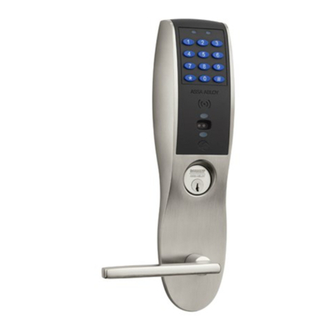
Other Assa Abloy Door Lock manuals

Assa Abloy Yale Assure Technical specifications

Assa Abloy

Assa Abloy Yale Assure Technical specifications

Assa Abloy Effeff 319 Series User manual

Assa Abloy

Assa Abloy Effeff 319 Series User manual

Assa Abloy Sargent Signature Series User manual
Assa Abloy

Assa Abloy Sargent Signature Series User manual

Assa Abloy Corbin Russwin SE LP10 CL3360 User manual

Assa Abloy

Assa Abloy Corbin Russwin SE LP10 CL3360 User manual

Assa Abloy 179A User guide

Assa Abloy

Assa Abloy 179A User guide

Assa Abloy PEMKO 3495 User manual

Assa Abloy

Assa Abloy PEMKO 3495 User manual

Assa Abloy ABLOY EL654 User manual

Assa Abloy

Assa Abloy ABLOY EL654 User manual

Assa Abloy Arrow Revolution U4A-YRHCPZW0 Technical specifications

Assa Abloy

Assa Abloy Arrow Revolution U4A-YRHCPZW0 Technical specifications

Assa Abloy KESO KEK i-handle S Operator's manual

Assa Abloy

Assa Abloy KESO KEK i-handle S Operator's manual

Assa Abloy ANYKEY User manual

Assa Abloy

Assa Abloy ANYKEY User manual

Assa Abloy Aptus Yale Doorman User manual

Assa Abloy

Assa Abloy Aptus Yale Doorman User manual

Assa Abloy Sargent FM-PE8700 Series User manual

Assa Abloy

Assa Abloy Sargent FM-PE8700 Series User manual

Assa Abloy Corbin Russwin Access 600 CL33600 TCRNE1... User manual

Assa Abloy

Assa Abloy Corbin Russwin Access 600 CL33600 TCRNE1... User manual

Assa Abloy Corbin Russwin TL3700 Series User manual

Assa Abloy

Assa Abloy Corbin Russwin TL3700 Series User manual

Assa Abloy 179E User guide

Assa Abloy

Assa Abloy 179E User guide

Assa Abloy NORTON RIXSON CG0M19 User manual

Assa Abloy

Assa Abloy NORTON RIXSON CG0M19 User manual

Assa Abloy Sargent PE80 Series User manual

Assa Abloy

Assa Abloy Sargent PE80 Series User manual

Assa Abloy Sargent IN220 User manual

Assa Abloy

Assa Abloy Sargent IN220 User manual

Assa Abloy Yale Assure Lock YRC226 Technical specifications

Assa Abloy

Assa Abloy Yale Assure Lock YRC226 Technical specifications

Assa Abloy Corbin Russwin FE6600 Series User manual

Assa Abloy

Assa Abloy Corbin Russwin FE6600 Series User manual

Assa Abloy Rixson 73ER User manual

Assa Abloy

Assa Abloy Rixson 73ER User manual

Assa Abloy Code Handle Manual

Assa Abloy

Assa Abloy Code Handle Manual

Assa Abloy ZI IKON eCLIQ N109 User manual

Assa Abloy

Assa Abloy ZI IKON eCLIQ N109 User manual

Assa Abloy Sargent 7800 Series User manual

Assa Abloy

Assa Abloy Sargent 7800 Series User manual

Popular Door Lock manuals by other brands

Lockly Secure LUX user manual

Lockly

Lockly Secure LUX user manual

Yale 630F installation instructions

Yale

Yale 630F installation instructions

Dormakaba SVA 2000 Mounting instructions

Dormakaba

Dormakaba SVA 2000 Mounting instructions

WFE Technology Corp. WAFERLOCK L379 manual

WFE Technology Corp.

WFE Technology Corp. WAFERLOCK L379 manual

Schlage Schlage LiNK brochure

Schlage

Schlage Schlage LiNK brochure

BANKSTON Associati Install instructions

BANKSTON

BANKSTON Associati Install instructions

Timewatch FGL14 user manual

Timewatch

Timewatch FGL14 user manual

Dorma RTS Series quick start guide

Dorma

Dorma RTS Series quick start guide

Wittkopp SmartCam installation instructions

Wittkopp

Wittkopp SmartCam installation instructions

Philips EasyKey Alpha user manual

Philips

Philips EasyKey Alpha user manual

Dorma RTS Series quick start guide

Dorma

Dorma RTS Series quick start guide

Simpled CF-YC user manual

Simpled

Simpled CF-YC user manual

LSDA R/V installation instructions

LSDA

LSDA R/V installation instructions

Maco SMART DEADBOLT Installation and user guide

Maco

Maco SMART DEADBOLT Installation and user guide

urmet domus 1083/12 Configuration guide

urmet domus

urmet domus 1083/12 Configuration guide

ILCO Unican DT-509275 AMM installation instructions

ILCO Unican

ILCO Unican DT-509275 AMM installation instructions

S&S LIVING SSL-R80 installation guide

S&S LIVING

S&S LIVING SSL-R80 installation guide

Philips EasyKey Alpha Series user manual

Philips

Philips EasyKey Alpha Series user manual

manuals.online logo
manuals.online logoBrands
  • About & Mission
  • Contact us
  • Privacy Policy
  • Terms and Conditions

Copyright 2025 Manuals.Online. All Rights Reserved.