manuals.online logo
Brands
  1. Home
  2. •
  3. Brands
  4. •
  5. Balanced Body
  6. •
  7. Fitness Equipment
  8. •
  9. Balanced Body CenterLine Tower Retrofit Instruction Manual

Balanced Body CenterLine Tower Retrofit Instruction Manual

Contact Us
1-800-PILATES | +1-916-388-2838
pilates.com | info@pilates.com
400-355 | 01.30.19
Installing the Balanced Body®CenterLine®
Tower Retrofit
Please take time to inspect the box for shipping damage prior to assembly. If any issues are found, immediately contact our customer
service department at 1-800-PILATES or +1-916-388-2838.
Read each step thoroughly and look at the diagrams before starting assembly. It is important that you follow the steps as they are
described in these instructions.
PARTS LIST (INCLUDED)
TOOLS PART NO QTY
3
⁄
16
” Allen wrench GEN9280 1
5
⁄
32
” Allen wrench GEN9282 1
5
⁄
16
” drill bit TOL1059 1
21mm x 1/2” wrench ALL0060 1
PARTS PART NO QTY
Tower Bracket 722-001 1
L shaped corner brackets 622-001 4
Long Vertical Tubes (with eyebolts) TRP0105 2
Short Horizontal Tube (eyebolts and
black safety strap)
TRP0100 1
Single D Loops 607-346 1 pair
Roll Down Bar 710-011 1
Wooden Push Through Bar for slider
assembly
707-288 1
Green Spring with clips SPR9000 1
Red Spring with clips SPR9001 1
Blue Spring with clips SPR9004 2
Long Red Spring with clips SPR9246 2
Long Gray Spring with clips SPR9245 2
Push Through Bar Slider assembly N/A 2
Push Through Bar Slider shoulder bolt 619-203 2
CenterLine Safety Strap 607-355 1
(Please use this list to make sure you have all the parts listed. If you are missing
a part, please contact our customer service department at 1-800-PILATES or
+1-916-388-2838)
TOOLS NEEDED (NOT INCLUDED):
»Hammer or mallet
»Power drill
»Socket wrench with
7
⁄
16
” &
1
⁄
2
” sockets.
Open end wrenches will also work.
HARDWARE:
Part Number QTY Part
GEN9232 6 Eyebolt,
1
⁄
4
”-20 x 3”
GEN9015 4 Bolt,
1
⁄
4
”-20 x 2”
GEN9305 20 Flat Washer,
1
⁄
4
”
210-050 6 Finish Washer
GEN9021 10 Lock Nut,
1
⁄
4
”-20
210-512 4 Carriage Bolt,
5
⁄
16
-18
GEN9013 4 Lock Nut,
5
⁄
16
-18
210-216 2 Flat Head Bolt
214-000 2 Knurled Knob
2
1. Remove all bolts from each of the casters with a 1⁄2” wrench
and the included 3⁄16” Allen wrench. Keep the castors, nuts
and bolts close by. You will need them in the following steps.
2. Hold the Tower bracket against the end of the Reformer frame
and bolt it in place using the upper / inside caster holes. Use
eyebolts (GEN9232), washers (GEN9305 & 210-050), and
nuts (GEN9021). Make sure the bracket is centered and square
on the frame and tighten the nuts. See figure A. Note: If the
bracket does not line up with the inner holes, use the outer
holes for the eye bolt and the inner holes for the flathead.
Fig A (only one side shown)
3. Using the included 5⁄16” drill bit (TOL1059), use the bracket as
a guide to drill the eight holes in the Reformer frame shown
in Figure B. On the top two slots, drill the holes as far to the
outside of the slots as possible. Try to drill straight through the
frame, not at an angle.
IMPORTANT NOTE: It is important that you do not push too hard
while drilling the holes or you might splinter the Reformer frame
when the drill bit breaks through to the other side. Once the drill
bit is most of the way through the wood, press just hard enough
to keep drilling.
Fig B
4. Loosely install the four
corner brackets with the
provided screws (GEN9015),
washers (GEN9305), and
nuts (GEN9021). Slide and
hold the corner brackets
against the inside of the
Reformer frame and then
tighten the bolts. See figure
C.
5. Using the included 5⁄16” drill bit (TOL1059) and the remaining
hole in each corner bracket as a guide, drill four holes in the
Reformer frame.
IMPORTANT NOTE: It is important that you do not push too hard
while drilling the holes or you might splinter the Reformer frame
when the drill bit breaks through to the other side. Once the drill
bit is most of the way through the wood, press just hard enough
to keep drilling.
6. Now that you have drilled all of the required holes in your
Reformer frame, it is time to unbolt and remove the bracket
so the final assembly steps can begin.
7. Insert a flat head screw
(210-216) into the upper/
outer holes of the casters as
shown, through the washer
(GEN9305) and thread into
the nut (GEN9021). Use
the same hardware that
was removed in step 1 and
place them into the bottom
two castor holes.See Figure
D. When three bolts are
holding the caster in place,
tighten them all. NOTE: The
flat head screw must be
tightened enough so that
the head is flush with the Reformer frame. Repeat for the
other castor.
8. Hold the Tower bracket against the end of the Reformer frame
and bolt in place with eyebolts (GEN9232), washers (GEN9305
& 210-050), and nuts (GEN9021) as shown in figure A. Make
sure the bracket is centered and square on the frame.
9. Install the corner brackets and all other bolts as shown in
figures E & F and then tighten all bolts. A hammer or mallet
should be used to tap the head of the four carriage bolts (210-
512) until the square portion is pushed into the frame and the
underside of the head sits flush against the frame. Once flush,
stop hammering.
Fig E (applies to top and bottom corner brackets. Only one side shown)
Fig C (only one side) shown)
Fig D (only one side shown)
3
Note: If the bracket does not line up with the inner holes, use
the outer holes for the eyebolt and the inner holes for the
flathead.
10. (Those who have purchased the full Tower system start
here.) Loosen the four set screws in the sockets on the Tower
bracket so the main tubes can slide through.
11. Remove the vertical tower system and place them into the
receiver bracket on the end of the Reformer. The knobs of the
sliders will be facing outwards as shown in Figure G. Make
sure when you place the tubes into the receiver that the loop
is facing forward, towards the carriage, see Figure H.
12. Now tighten all set screws on the bracket receivers. If PTB
sliders do not move easily, the vertical tube set screws must
be loosened and the vertical tubes rotated into alignment.
Then re-tighten set screws.
13. Your shoulder rests will now be held in place by a detent pin or
a knob (214-000) for easy removal and installation. Drop the
screw through the shoulder rest from the top and tighten the
knob from under the carriage.
HOW TO ADJUST YOUR SLIDING PUSH THROUGH BAR
Position your hands on the outside of each slider. Place your
middle and/or ring fingers under the silver base of the knob; right
where the black body of the knob threads into. Place your index
finger and thumb around the knob itself. Pull each of the knobs
outwards, away from the vertical tubes, until they stop. Using the
same force on each arm, move the slider upwards or downwards
to each new location. Once you near a new location slightly
release the outward pull of the knobs. The pins will automatically
fall into the next position when aligned.
CLEANING AND MAINTENANCE
It is recommended to check to ensure the pins in the plunger
knobs protrude and lock into the vertical tubes. First pull both
knobs out and start moving the sliders to a different position.
Release the knobs before the next hole and continue to slide the
system. Once over a hole the pin of the knob will drop into the
opening. Once each slider is in a new position apply a down force
on the PTB directly downwards. The pins of the sliders should
not come out of the holes. If the pins do not stay in the tube
holes, the pull knobs need to be replaced; call Balanced Body for
replacement parts.
Fig F (only one side shown)
GEN9232
210-050
GEN9305
GEN9021
GEN9305
Fig G
Knobs outward
Strap loops face
the reformer.
Fig H
CENTERLINE TOWER MAT CONVERSION:
1. Remove the shoulder rest knob and bolt, then push the
shoulder rest toward the carriage and pull up to remove the
shoulder rest. Loosely assemble the knob and bolt on each
shoulder rest and store them under the Reformer.
2. Disconnect all of the Reformer springs from the spring bar
and roll the carriage toward the tower.
3. Rotate the footbar support up to the padded section of the
footbar and then lay the footbar down onto the frame rails. It
should now be inside the frame and lower than the top of the
frame.
4. Inspect the two Tower mats. One of them will have two vinyl
flaps installed on the underside with Velcro for shipping
purposes. Detach, rotate, and re-attach the flaps so they hang
down from the edge of the mat. This is the mat that will go at
the tower end of the Reformer. See figure J. Be sure that the
flaps are aligned with the eye bolts when the mat is installed
so they protect the mat from springs attached to the lowest
eye bolts. The feet on the bottom of the mat fit inside the
Reformer frame to keep it in place, now push it all of the way
toward the tower.
Figure J
5. The other mat is now installed in the same way at the foot
end of the Reformer.
QUESTIONS?
Contact Balanced Body Technical Support at 1-800-PILATES or
+1-916-388-2838.
Balanced Body is not responsible for equipment damage
resulting from incorrect installation.
Contact Us
1-800-PILATES | +1-916-388-2838
pilates.com | info@pilates.com
400-355 | 01.30.19

Other Balanced Body Fitness Equipment manuals

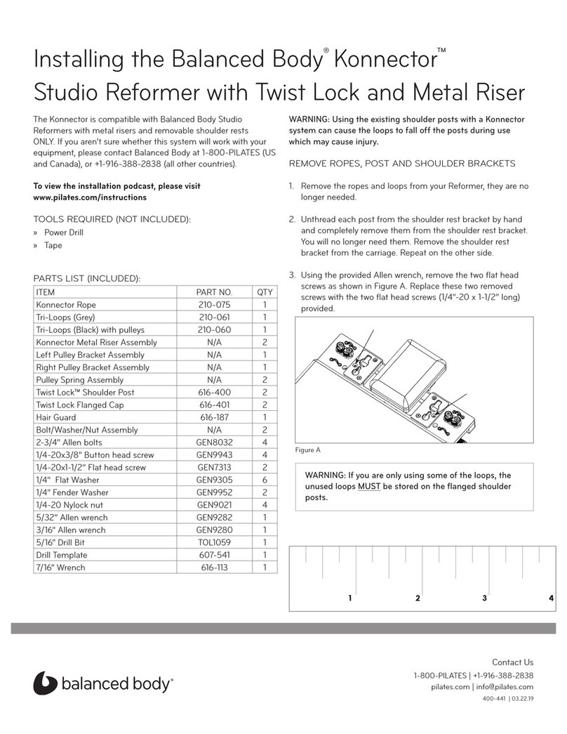
Balanced Body Studio Reformer User manual

Balanced Body

Balanced Body Studio Reformer User manual

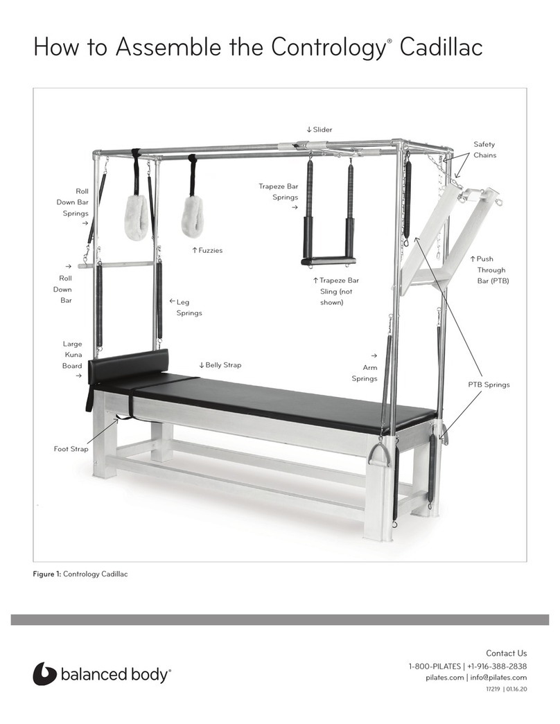
Balanced Body Cadillac User manual

Balanced Body

Balanced Body Cadillac User manual

Balanced Body Arm Chair User manual

Balanced Body

Balanced Body Arm Chair User manual

Balanced Body Konnector Instruction Manual

Balanced Body

Balanced Body Konnector Instruction Manual

Balanced Body Allegro Instruction sheet

Balanced Body

Balanced Body Allegro Instruction sheet

Balanced Body MOTR Installation instructions

Balanced Body

Balanced Body MOTR Installation instructions

Balanced Body Pilates IQ Reformer Manual

Balanced Body

Balanced Body Pilates IQ Reformer Manual

Balanced Body Reformer Trapeze Combination Administrator Guide

Balanced Body

Balanced Body Reformer Trapeze Combination Administrator Guide

Balanced Body Allegro 1A Instruction Manual

Balanced Body

Balanced Body Allegro 1A Instruction Manual

Balanced Body CoreAlign User manual

Balanced Body

Balanced Body CoreAlign User manual

Balanced Body Cadillac Trapeze Table Administrator Guide

Balanced Body

Balanced Body Cadillac Trapeze Table Administrator Guide

Balanced Body Allegro 1B Instruction Manual

Balanced Body

Balanced Body Allegro 1B Instruction Manual

Balanced Body Contrology Cadillac User manual

Balanced Body

Balanced Body Contrology Cadillac User manual

Balanced Body IQ REFORMER User manual

Balanced Body

Balanced Body IQ REFORMER User manual

Balanced Body Konnector User manual

Balanced Body

Balanced Body Konnector User manual

Balanced Body Wall Tower Administrator Guide

Balanced Body

Balanced Body Wall Tower Administrator Guide

Balanced Body Rialto with Riser Konnector Instruction Manual

Balanced Body

Balanced Body Rialto with Riser Konnector Instruction Manual

Balanced Body Reformer Trapeze Combination User manual

Balanced Body

Balanced Body Reformer Trapeze Combination User manual

Balanced Body Allegro User manual

Balanced Body

Balanced Body Allegro User manual

Balanced Body Allegro Legs Kit Instruction sheet

Balanced Body

Balanced Body Allegro Legs Kit Instruction sheet

Balanced Body CenterLine Reformer User manual

Balanced Body

Balanced Body CenterLine Reformer User manual

Balanced Body Tower on the Allegro 2 Instruction Manual

Balanced Body

Balanced Body Tower on the Allegro 2 Instruction Manual

Balanced Body CoreAlign User manual

Balanced Body

Balanced Body CoreAlign User manual

Balanced Body Konnector LITE Instruction Manual

Balanced Body

Balanced Body Konnector LITE Instruction Manual

Popular Fitness Equipment manuals by other brands

Aerofit MLE-200 owner's manual

Aerofit

Aerofit MLE-200 owner's manual

Weider Pro 7500 user manual

Weider

Weider Pro 7500 user manual

PSS 4000 Installation, operation and maintenance guide

PSS

PSS 4000 Installation, operation and maintenance guide

Precor C556 Service manual

Precor

Precor C556 Service manual

Matrix A30 Assembly

Matrix

Matrix A30 Assembly

Xterra 16468201US owner's manual

Xterra

Xterra 16468201US owner's manual

Smooth Fitness SMOOTH AGILE user manual

Smooth Fitness

Smooth Fitness SMOOTH AGILE user manual

Merrithew Health & Fitness Stability Chair owner's manual

Merrithew Health & Fitness

Merrithew Health & Fitness Stability Chair owner's manual

Stamina 1690 POWER TOWER owner's manual

Stamina

Stamina 1690 POWER TOWER owner's manual

Weslo momentum G 3.2 user manual

Weslo

Weslo momentum G 3.2 user manual

Torque XFIB-104 Assembly guide

Torque

Torque XFIB-104 Assembly guide

Hattrick-Pro COASTER S user manual

Hattrick-Pro

Hattrick-Pro COASTER S user manual

LesMills SMARTBAR Instructions for use

LesMills

LesMills SMARTBAR Instructions for use

Master MAS4A093 user manual

Master

Master MAS4A093 user manual

Saratoga Spa Spirit 690 Assembly guide

Saratoga Spa

Saratoga Spa Spirit 690 Assembly guide

Ironmaster Quick-Lock Dumbells operating instructions

Ironmaster

Ironmaster Quick-Lock Dumbells operating instructions

Body Craft BC-F602 Assembly and operating instructions

Body Craft

Body Craft BC-F602 Assembly and operating instructions

Finnlo AUTARK 600 manual

Finnlo

Finnlo AUTARK 600 manual

manuals.online logo
manuals.online logoBrands
  • About & Mission
  • Contact us
  • Privacy Policy
  • Terms and Conditions

Copyright 2025 Manuals.Online. All Rights Reserved.