manuals.online logo
Brands
  1. Home
  2. •
  3. Brands
  4. •
  5. BEGA
  6. •
  7. Outdoor Light
  8. •
  9. BEGA 84 462 Manual

BEGA 84 462 Manual

Other BEGA Outdoor Light manuals

BEGA 84 696 User manual

BEGA

BEGA 84 696 User manual

BEGA 24 353 Manual

BEGA

BEGA 24 353 Manual

BEGA 67 548.2 User manual

BEGA

BEGA 67 548.2 User manual

BEGA 84 427 User manual

BEGA

BEGA 84 427 User manual

BEGA 7264 User manual

BEGA

BEGA 7264 User manual

BEGA 88 863 Manual

BEGA

BEGA 88 863 Manual

BEGA 24 110 Manual

BEGA

BEGA 24 110 Manual

BEGA 77 814 User manual

BEGA

BEGA 77 814 User manual

BEGA 24 326 User manual

BEGA

BEGA 24 326 User manual

BEGA 84 218 Manual

BEGA

BEGA 84 218 Manual

BEGA 77 911 Manual

BEGA

BEGA 77 911 Manual

BEGA 84 422 User manual

BEGA

BEGA 84 422 User manual

BEGA 98 006 Manual

BEGA

BEGA 98 006 Manual

BEGA 33 160 Series User manual

BEGA

BEGA 33 160 Series User manual

BEGA 84 433 User manual

BEGA

BEGA 84 433 User manual

BEGA 84 240 Manual

BEGA

BEGA 84 240 Manual

BEGA 24 011 Manual

BEGA

BEGA 24 011 Manual

BEGA 85 046 User manual

BEGA

BEGA 85 046 User manual

BEGA 24 216 Manual

BEGA

BEGA 24 216 Manual

BEGA 84 021 User manual

BEGA

BEGA 84 021 User manual

BEGA 99 635 User manual

BEGA

BEGA 99 635 User manual

BEGA 71 601 User manual

BEGA

BEGA 71 601 User manual

BEGA 84 761 User manual

BEGA

BEGA 84 761 User manual

BEGA 99 558 Manual

BEGA

BEGA 99 558 Manual

Popular Outdoor Light manuals by other brands

Kichler Lighting HELEN 37536 instructions

Kichler Lighting

Kichler Lighting HELEN 37536 instructions

Thorn OXANE L installation instructions

Thorn

Thorn OXANE L installation instructions

esotec Solar Globe Light multicolor 20 operating instructions

esotec

esotec Solar Globe Light multicolor 20 operating instructions

mitzi HL200201 ELLIS Assembly and mounting instructions

mitzi

mitzi HL200201 ELLIS Assembly and mounting instructions

HEPER TILA S AFX 3 Module Installation & maintenance instructions

HEPER

HEPER TILA S AFX 3 Module Installation & maintenance instructions

Designplan TRON 180 installation instructions

Designplan

Designplan TRON 180 installation instructions

Sealey LED37 instructions

Sealey

Sealey LED37 instructions

nordlux VEJERS Mounting instruction

nordlux

nordlux VEJERS Mounting instruction

SImx ELITE LED LHTC637 installation instructions

SImx

SImx ELITE LED LHTC637 installation instructions

GEV CAROLINE 10833 manual

GEV

GEV CAROLINE 10833 manual

WE-EF PFL540 LED Installation and maintenance instructions

WE-EF

WE-EF PFL540 LED Installation and maintenance instructions

HEPER DOGO Side LW6048.585-US Installation & maintenance instructions

HEPER

HEPER DOGO Side LW6048.585-US Installation & maintenance instructions

HEPER LW8034.003-US Installation & maintenance instructions

HEPER

HEPER LW8034.003-US Installation & maintenance instructions

HEPER MINIMO Installation & maintenance instructions

HEPER

HEPER MINIMO Installation & maintenance instructions

LIGMAN BAMBOO 3 installation manual

LIGMAN

LIGMAN BAMBOO 3 installation manual

Maretti TUBE CUBE WALL 14.4998.04 quick start guide

Maretti

Maretti TUBE CUBE WALL 14.4998.04 quick start guide

Maxim Lighting Carriage House VX 40428WGOB installation instructions

Maxim Lighting

Maxim Lighting Carriage House VX 40428WGOB installation instructions

urban ambiance UQL1273 installation instructions

urban ambiance

urban ambiance UQL1273 installation instructions

manuals.online logo
manuals.online logoBrands
  • About & Mission
  • Contact us
  • Privacy Policy
  • Terms and Conditions

Copyright 2025 Manuals.Online. All Rights Reserved.

Installation and Technical Information
BEGA
Due to the dynamic nature of lighting products and the associated technologies, luminaire data on this sheet is subject to change at the discretion of BEGA North America. For the most current technical data, please refer to bega-us.com
BEGA 1000 Bega Way, Carpinteria, CA 93013 (805)684-0533 © copyright BEGA 2023
Overview:
LED Watts: 11.5W
System Watts: 18.0W
Controllability: 0-10V, TRIAC, and ELV dimmable
Weight: 27.1 lbs.
Protection Class: IP65
Tools Required:
• 5mm hex head screwdriver
• 10 mm socket
Figure 1: (BASE ORIENTATION - EMPK OPTION)
DIN RAIL NOTCH
LOCATION
ANCHOR BOLT
LOCATIONS
Bollard - Asymmetric at beam 84 462
Dimensions
A: 8-5/8”
B: 38-7/8”
C: 8-5/8”
Maintenance:
Clean regularly with solvent-free cleaner
removing dirt and debris. Do not use high
pressure cleaners.
Replacement Parts
See label inside of xture for LED replacement
part number.
Consult factory for all other replacement
components.
Luminaire Accessories
Please refer to the appropriate accessory installation
sheet for further instruction when applicable.
Mounting Accessories
Please refer to the appropriate accessory installation
sheet for further instruction when applicable.
Updated: 03/22/23
84 462 1 of 3
Notice to Installer:
1. See page 3 for specic product safety warnings.
2. Fixture may be damaged if connected to conduit systems that contain water - Article
300-5G of the National Electric Code requires that “Conduits or raceway through which
moisture may contact energized live parts shall be sealed or plugged at either or both
ends.”
3. For proper installation, an accompanying bollard head must be selected with the bollard
tube.
4. 79 818 anchorage kit (included) must be installed in concrete pad/foundation.
5. It is recommended that when installing in planting areas the bollard base be slightly
elevated to avoid prolonged submerging during heavy rains.
6. Wet location listing does not imply suitability for exposure to standing water for
prolonged periods of time.
7. LEDs are high-quality electronic components! Please avoid touching the light output
opening of the LED directly during installation.
8. Emergency LED driver in bollard tube is for use with 120V OR 277V ONLY. This driver
is not 120V-277V.
79 818 anchorage installation:
1. Provide means to bring supply wiring to the bollard in accordance with local code. (20”
of supply wire above nished grade is required to make connections.)
2. Assemble anchorage kit. Unscrew the (3) hex bolts from the female couplers. Remove
each hex bolt and washer. Align each anchor bolt with the hole in the template. Attach
each anchor bolt to the template by replacing the washer and hex bolt and tighten.
*NOTE (FIGURE 1): FOR EMPK OPTION THE ORIENTATION OF THE BASE IS
CRUCIAL FOR PROPER INSTALLATION.
3. Determine the nished grade for the application. Use leveling hardware to adjust
template to desired nished height after pouring.
4. Install anchorage kit using either method:
A. Attach template to forming or cross bracing using the (2) nail holes provided
in the template. Level template properly. Pour concrete.
B. Insert anchorage assembly into poured concrete. Concrete must be vibrated
to ensure proper anchorage setting. Level template properly.
(See page 2 for luminaire installation)
Installation and Technical Information
BEGA
Due to the dynamic nature of lighting products and the associated technologies, luminaire data on this sheet is subject to change at the discretion of BEGA North America. For the most current technical data, please refer to bega-us.com
BEGA 1000 Bega Way, Carpinteria, CA 93013 (805)684-0533 © copyright BEGA 2023
Overview:
LED Watts: 11.5W
System Watts: 18.0W
Controllability: 0-10V, TRIAC, and ELV dimmable
Weight: 27.1 lbs.
Protection Class: IP65
Tools Required:
• 5mm hex head screwdriver
• 10mm socket
Figure 2
Bollard - Asymmetric at beam 84 462
Dimensions
A: 8-5/8”
B: 38-7/8”
C: 8-5/8”
Maintenance:
Clean regularly with solvent-free cleaner
removing dirt and debris. Do not use high
pressure cleaners.
Replacement Parts
See label inside of xture for LED replacement
part number.
Consult factory for all other replacement
components.
Luminaire Accessories
Please refer to the appropriate accessory installation
sheet for further instruction when applicable.
Mounting Accessories
Please refer to the appropriate accessory installation
sheet for further instruction when applicable.
Updated: 03/22/23
84 462 2 of 3
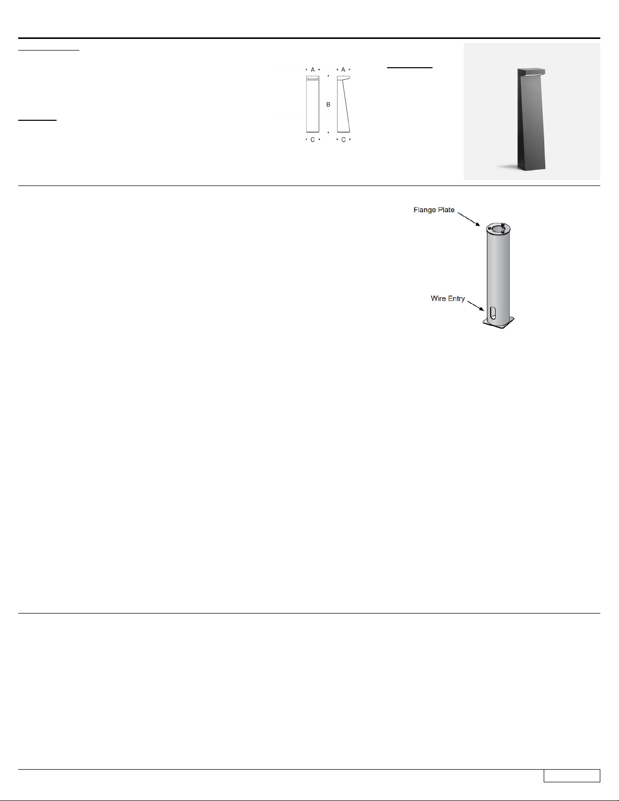
70 896 direct burial (optional) anchorage installation:
1. Provide means to bring supply wiring to the conduit entry location per local code (20”
of supply wire above nished grade is required to make connections.) (FIGURE 2)
2. Prepare soil for anchorage or cast the post in concrete.
3. Make sure anchorage is installed rmly into the ground and mounted level to the
surface. NOTE: ENSURE THAT THE FLANGE PLATE IS ENTIRELY LEVEL AND
FLUSH WITH THE TOP EDGE OF THE SURFACE
4. Remove (3) mounting bolts and washers from the anchorage unit
5. Align mounting base of the bollard tube, place onto top of anchorage post.*NOTE
(FIGURE 1, page 1): FOR EMPK OPTION THE ORIENTATION OF THE BASE IS
CRUCIAL FOR PROPER INSTALLATION.
Luminaire 84 462 installation:
1. Ensure anchorage is set with the nished grade, as the anchorage must not be below
the nished grade.
2. Loosen the set screw at the base of the bollard, rotate and remove the mounting base.
3. Secure mounting base to anchorage using the 3 hex bolts supplied with the
anchorage kit.
4. Pull wiring from xture to make connections with supply wiring.
5. Make supply wiring and luminaire wiring connections inside luminaire:
MAIN VOLTAGE SUPPLY WIRE TO BLACK LUMINAIRE WIRE
NEUTRAL (COMMON) SUPPLY WIRE TO WHITE LUMINAIRE WIRE
GREEN GROUND WIRE TO GREEN LUMINAIRE WIRE
Dimming (if applicable):
DIMMING CONTROL WIRE (+) TO POSITIVE DRIVER DIM CONTROL WIRE
DIMMING CONTROL WIRE (-) TO NEGATIVE DRIVER DIM CONTROL WIRE
6. Place luminaire over the mounting base rotate into desired position.
7. Tighten set screw to x the luminaire into place.
Luminaire 84 462 EMPK (optional):
1. EMPK wiring instructions:
SWITCHED MAIN VOLTAGE SUPPLY WIRE TO BLACK LED DRIVER WIRE;
NEUTRAL (COMMON) SUPPLY WIRE TO WHITE LUMINAIRE WIRE;
GREEN GROUND WIRE TO GREEN LUMINAIRE WIRE.
SWITCH/TIMER SUPPLY WIRE TO RED/WHITE LUMINAIRE WIRE
Dimming (if applicable):
DIMMING CONTROL WIRE (+) TO POSITIVE DRIVER DIM CONTROL WIRE.
DIMMING CONTROL WIRE (-) TO NEGATIVE DRIVER DIM CONTROL WIRE.
NOTE: Battery should be charged once luminaire is fully installed on site, allow 24
hours for battery to reach full charge.
Installation and Technical Information
BEGA
Due to the dynamic nature of lighting products and the associated technologies, luminaire data on this sheet is subject to change at the discretion of BEGA North America. For the most current technical data, please refer to bega-us.com
BEGA 1000 Bega Way, Carpinteria, CA 93013 (805)684-0533 © copyright BEGA 2023
Product Safety Warnings:
THIS PRODUCT MUST BE INSTALLED IN ACCORDANCE WITH THE APPLICABLE INSTALLATION CODE BY A PERSON
FAMILIAR WITH THE CONSTRUCTION AND OPERATION OF THE PRODUCT AND THE HAZARDS INVOLVED.
SUITABLE FOR WET LOCATIONS.
MIN 60°C SUPPLY CONDUCTORS.
CE PRODUIT DOIT ÊTRE INSTALLÉ SELON LE CODE D’INSTALLATION PERTINENT, PAR UNE PERSONNE QUI CONNAÎT
BIEN LE PRODUIT ET SON FONCTIONNEMENT AINSI QUE LES RISQUES INHÉRENTS.
CONVIENT AUX EMPLACEMENTS MOUILLÉS.
LES FILS D’ALIMENTATION 60°C MIN.
Updated: 03/22/23
3 of 3
84 462
Bollard - Asymmetric at beam 84 462