Installation and Technical Information
BEGA
In the interest of product improvement, BEGA reserves the right to make technical changes without notice.
BEGA 1000 Bega Way, Carpinteria, CA 93013 (805)684-0533 Fax (805)566-9474 www.bega-us.com © Copyright BEGA-US 2018
LED linear light building element 84 875
84 875
4/27/2018
Notice to Installer for 84 875:
1. Fixture may be damaged if connected to conduit systems that contain water - Article 300-
5G of the National Electric Code requires that “Conduits or raceways through which
moisture may contact energized live parts shall be sealed or plugged at either or both
ends.”
2. 79 803 anchorage kit must be installed in concrete foundation. Once anchorage is
installated, xture cannot be reoriented!
3. The size of the foundation depends on the topgraphy, condition of soil and wind load.
Foundation design must be determined by project structural engineer.
4. Anchorage top MUST be level or slightly above nished grade. Attention to alignment,
leveling, and location is required for proper installation.
5. Wet location listing does not imply suitability for exposure to standing water for long
periods of time.
6. LEDs are high-quality electronic components! Please avoid touching the light
output opening of the LED directly during installation.
7. See page 3 for specic product safety warnings.
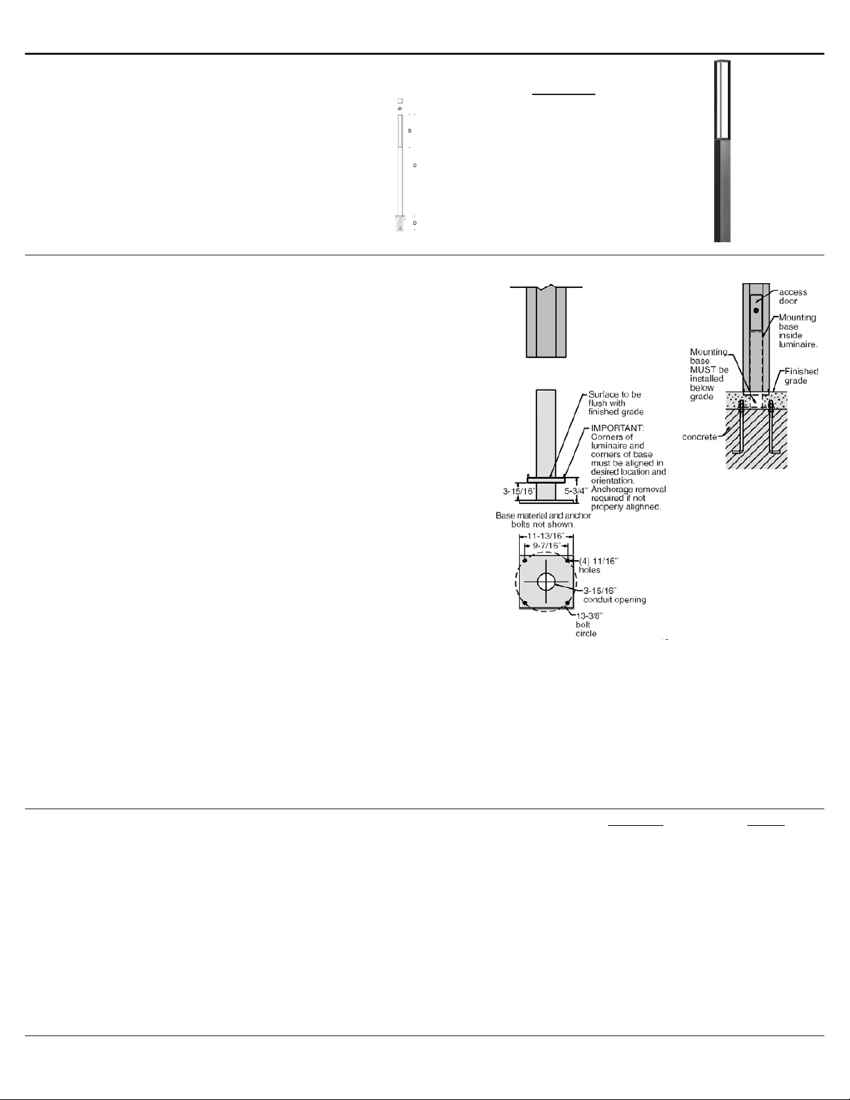
79 803 anchorage installation:
1. Provide means to bring supply wiring to linear element in accordance with local code. The
template has a 3-15/16” conduit hole for conduit entry. Provide adequate foundation
reinforcement for the intended load (by others).
2. Use template and anchor bolts provided to assemble anchorage kit to be set. Make sure
anchor bolts do not protrude from lower concrete foundation more than 2-1/4”.
3. Refer to Figure 2 to establish location of lower concrete foundation. The anchorage kit
MUST be buried. The top of the lower concrete foundation MUST be 5-3/4” BELOW
nished grade for proper installation.
4. Align and level anchorage kit so that the corners of the square template are aligned with
the same desired location and orientation as the corners of the square linear element.
5. Install anchorage kit using either method:
A. Attach template to forming and level properly.
B. Insert anchorage kit into poured concrete. Concrete must be vibrated to ensure
proper anchorage setting. Level template properly.
Figure 1
Tools Required:
5mm hex key
Adjustable wrench
Protection Class: IP65
Weight: 57.4 lbs
Dimensions
A: 6-3/8 x 6-3/8 ”
B: 48-3/8 ”
C: 157-1/2 ”
Relamping/Maintenance
No relamping required.
Lamp: 46.8W LED module
Description
Lens
LED driver
LED module (3000K) (x12)
LED module (4000K) (x12)
Part No
15000355.6
76084-1400
LED-0701/830
LED-0701/840
Page 1 of 4
square-Linear element
suitable for wet locations.
4mm and 8mm Hex Key
Special tool (provided)
BEGA Installation and Technical Information
Tools
8 "
177 "
8945MH
UL listed,
IP 65
127.6 lbs
Protection Class:
8945MH:
890B anchorage kit must be installed in concrete foundation.1.
Anchorage kit 890B is buried below finished grade. Attention to alignment, leveling, and
location is required for proper installation.
2.
890B
installation:
Provide means to bring supply wiring to linear element in accordance with local code. The
template has a 3-15/16" conduit hole for conduit entry. Provide adequate foundation
reinforcement for the intended load (by others).
1.
Use template and anchor bolts provided to assemble anchorage kit to be set. Make sure
anchor bolts do not protrude from lower concrete foundation more than 2-1/4" as shown.
2.
Please refer to figure to establish location of lower concrete foundation. The anchorage kit
MUST BE buried. The top of the lower concrete foundation MUST be 5-3/4" BELOW finished
grade for proper installation. Position anchorage and level template properly.
3.
Align and level anchorage kit so the corners of the square template are aligned with the
desired location and orientation of the corners of the square linear element. See figure.
4.
Install anchorage kit using either method: A. Attach template to forming and level properly.
B. Insert anchorage kit into poured concrete. Concrete must be vibrated to ensure proper
anchorage setting. Level template properly.
5.
8945MH
installation:
Once the anchorage is set, remove template and hardware.1.
Pull supply wiring to a length where splices can be seen and made through the access
door.
2.
Route supply wiring through the mounting base and install mounting base using hardware
provided. Complete finished grade. See figure.
3.
To insert lamp, loosen (4) M5 socket head screws on glass trim and remove glass and
reflector.
4.
Insert lamp(s) and replace reflector and glass trim.5.
Use special tool provided to unlock the access door lock and remove access door. Route
the luminaire wiring down and out the hand hold for connections to be made later.
6.
Loosen (8) M10 set screws at the base of the light element and place the light element over
the mounting base. Tighten (8) M10 set screws to secure to base.
7.
Make supply wiring and luminaire wiring connections inside the luminaire:
MAIN VOLTAGE SUPPLY WIRE TO BLACK LUMINAIRE WIRE
NEUTRAL (COMMON) SUPPLY WIRE TO WHITE LUMINAIRE WIRE
GREEN GROUND WIRE TO GREEN LUMINAIRE WIRE
8.
Replace access door and lock.9.
Relamping/Maintenance Accessories Replacement Parts
Lamp:
Philips
T6
Disassemble glass trim and glass. Clean dirt and
deposits from the luminaire and glass using only
solvent-free cleaners. Relamp and replace gasket if
damaged. Reassemble.
Description Part No
Diffuser
Gasket
Lampholder
Ballast (120/208/240/277V)
140533
830801
74121
75146
(1)
MH
Please refer to the appropriate
accessory installation sheet for
further instruction when applicable.
Anchorage Kit - included. 890B
In
Bega Way, Carpinteria, CA
Figure 2


