manuals.online logo
Brands
  1. Home
  2. •
  3. Brands
  4. •
  5. BEGA
  6. •
  7. Outdoor Light
  8. •
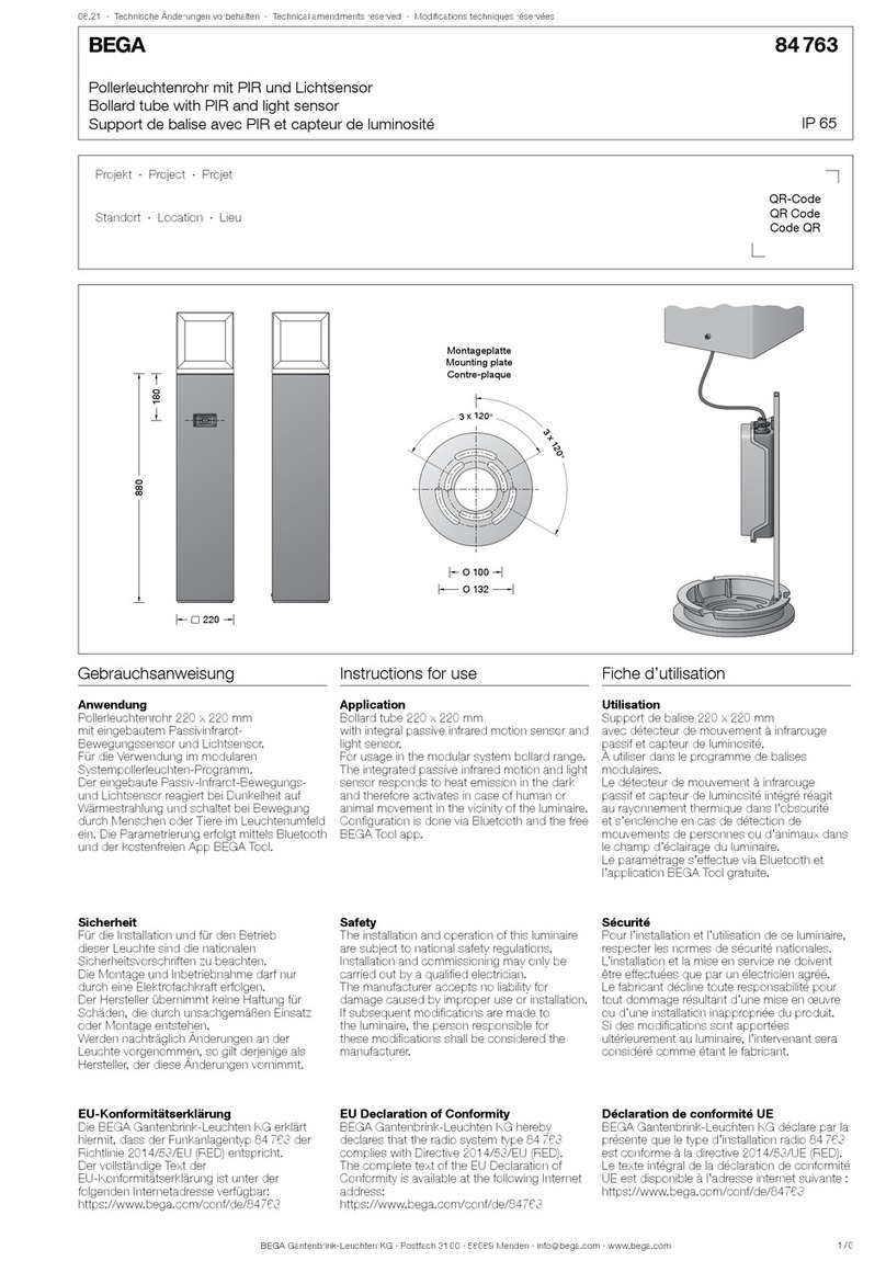
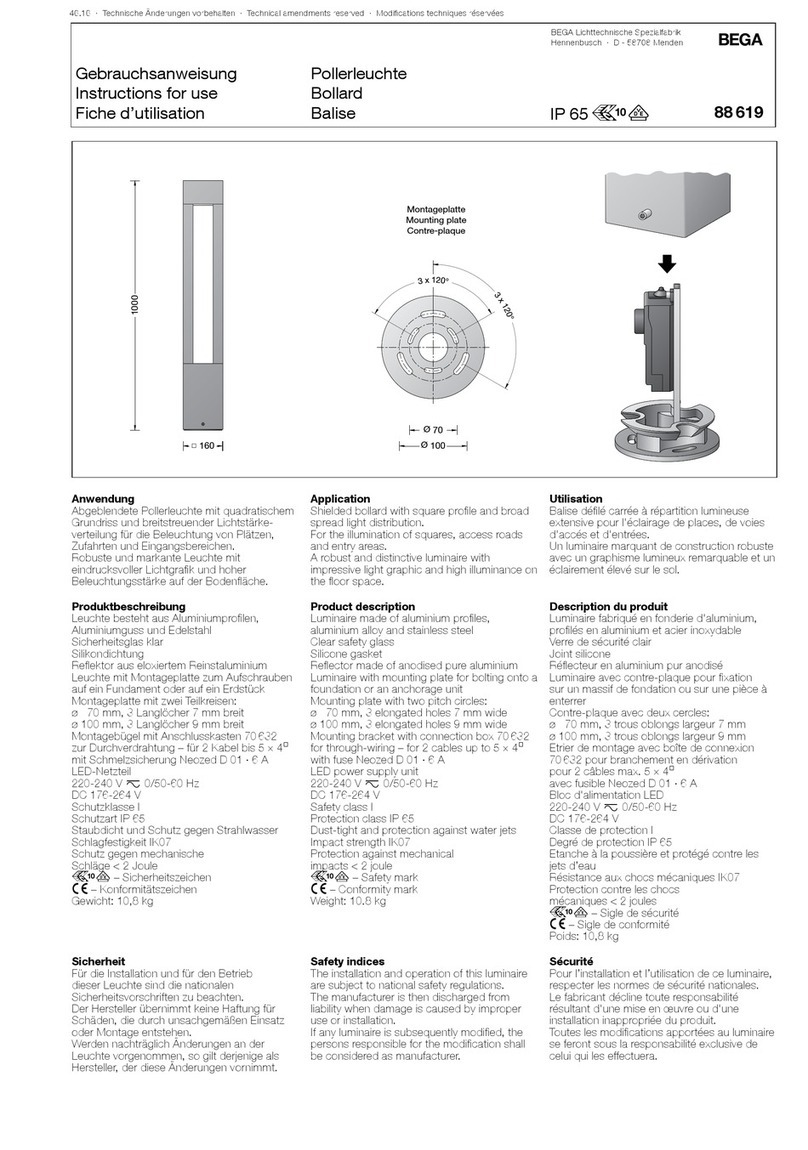
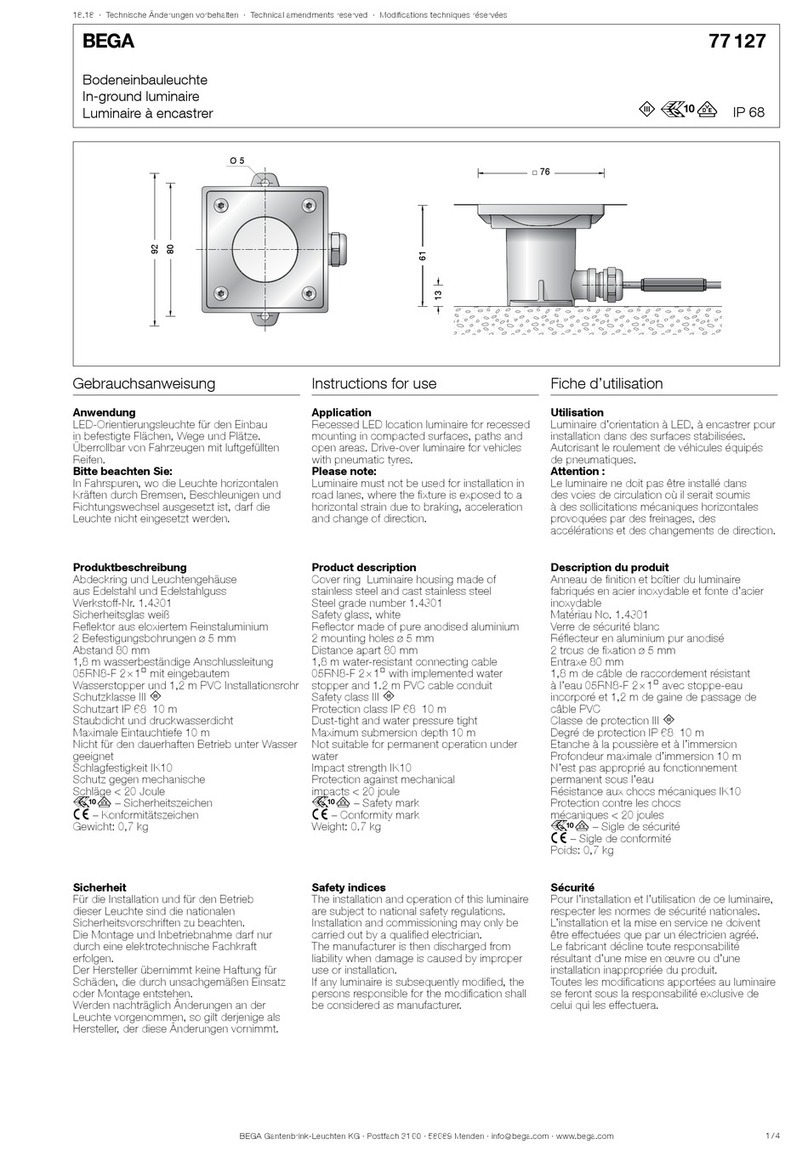
  9. BEGA 70 238 User manual

BEGA 70 238 User manual

BEGA Gantenbrink-Leuchten KG · Postfach 31 60 · 58689 Menden · info@bega.com · www.bega.com
50.17 · Technische Änderungen vorbehalten · Technical amendments reserved · Modications techniques réservées
IP X4
!
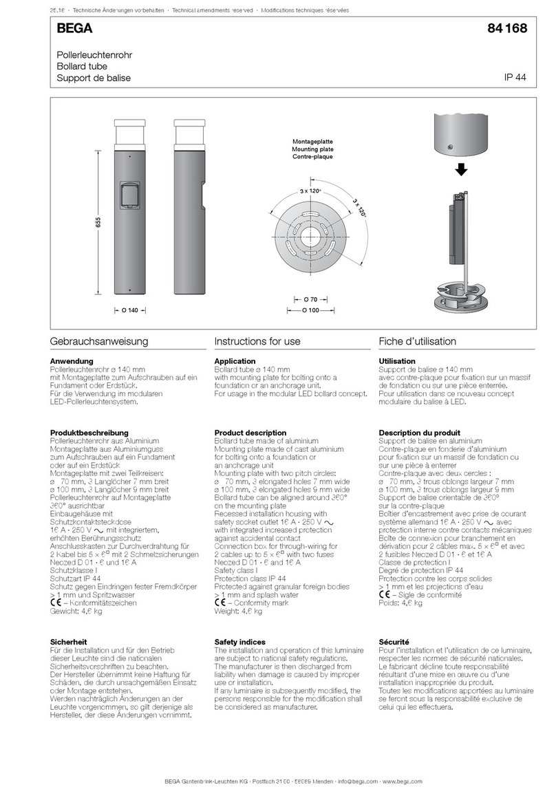
Anschlusssäule
Connecting Pillar
Borne d’alimentation
70 238
v
850
Ø 132
3
x
1
2
0
°
Montageplatte
Mounting plate
Contre-plaque
Ø 265
Ø 300
Ø 80Ø 80
Gebrauchsanweisung Instructions for use Fiche d’utilisation
Anwendung
Ortsfeste, abschließbare Anschlusssäule mit
Installationseinsätzen.
In besonders robuster Ausführung für die
Stromversorgung in privaten und öffentlichen
Anlagen oder gewerblichen Kleinbetrieben.
Application
Permanent lockable connecting pillar with
installation accessories.
Very strong construction for power supply in
public or industrial facilities.
Utilisation
Borne d’alimentation verrouillable pour
installation xe avec équipements électriques.
Fabrication particulièrement robuste pour
l’alimentation en courant électrique
d’installations publiques et commerciales.
Produktbeschreibung
Anschlusssäule besteht aus Aluminiumguss,
Aluminium und Edelstahl
Montageplatte mit elektrischer Einrichtung
zum Aufschrauben auf ein Fundament oder
auf ein Erdstück
Montageplatte mit 3 Langlöchern,
Breite 9mm, Drehbereich 60°,
Teilkreis ø 132mm
Abschließbare Tür
Sicherheitsschloss BKS mit 2 Schlüsseln
Durchstecköffnung für Stecker mit
Leitung, Breite 120mm
Anschlusssäule komplett verdrahtet mit:
3 Schutzkontaktsteckdosen
nach DIN 49440-1
16A · 250 V y
3 CEE-Steckdosen
nach DIN VDE 0623, EN 60309-2
16A · 250 V y
3 polig · 1P + N + PE
Kennfarbe blau
2 CEE-Steckdosen
nach DIN VDE 0623, EN 60309-2
16A · 415 V y
5 polig · 3P + N + PE
Kennfarbe rot
1 FI Schutzschalter 4 polig 40A / 30 mA
2 Leitungsschutzschalter 3 polig C16 A
6 Leitungsschutzschalter 1 polig C16 A
Betriebstemperatur: -25 °C bis 40 °C
Anschlussklemme 5-polig
Klemmbereich bis 16 mm@
Klemmenbelegung L1 · L2 · L3 · N · PE
zum Anschluss an ein 230/400 V
Drehstrom-Vierleitersystem
Kurzschlussfestigkeit max. 10 kA
Bemessungsbelastungsfaktor: 0,6
Schutzklasse I
v– Sicherheitszeichen
c – Konformitätszeichen
Gewicht: 18,9 kg
Product description
Connecting pillar made of aluminium alloy,
aluminium and stainless steel
Mounting plate with electrical unit for bolting
onto a foundation or an anchorage unit
Mounting plate with 3 enlongated holes
Width 9 mm, rotation range 60°
Pitch circle ø 132mm
Lockable door
Safety lock BKS with 2 keys
Access hole for plug with cable, width 120mm
The connecting pillar is completely wired with:
3 safety socket outlets
according to DIN49440-1
16A · 250 V y
3 CEE-socket outlets
according to DINVDE 0623, EN60309-2
16A · 250 V y
3-pole · 1P + N + PE
Identication colour blue
2 CEE-socket outlets
according to DIN VDE 0623, EN60309-2
16A · 415 V y
5-pole · 3P + N + PE
Identication colour red
1 fault current circuit breaker
4-pole 40A / 30 mA
2 line circuit breakers 3-pole C16A
6 line circuit breakers 1-pole C16A
Operating temperature: -25 °C to 40 °C
Connecting terminal 5-pole
Clamping range up to 16 mm@
Terminal conguration L1 · L2 · L3 · N · PE
for connection to 230/400 V
four-wire system
Short-circuit-proof max. 10 kA
Rated diversity factor: 0.6
Safety class I
v– Safety mark
c – Conformity mark
Weight: 18.9 kg
Description du produit
Borne d’alimentation fabriquée en fonderie
d’alu,
aluminium et acier inoxydable
Contre-plaque avec équipement électrique
pour xation par vis sur un massif de fondation
ou sur une pièce à enterrer
Contre-plaque avec 3 trous oblongs,
largeur 9 mm, réglage 60°
sur un cercle de ø 132mm
Porte verrouillable
Serrure de sécurité BKS avec 2 clefs
Ouverture pour passage de câbles et ches
largeur 120mm
Borne d'alimentation entièrement câblée
avec :
3 prises de courant système allemand
selon DIN 49440-1
16A · 250 V y
3 prises de courant CEE selon
DIN VDE 0623, EN 60309-2
16A · 250 V y
tripolaire · 1P + N + T
couleur bleue
2 prises de courant CEE selon
DIN VDE 0623, EN 60309-2
16A · 415 V y
5 pôles · 3P + N + T
couleur rouge
1 disjoncteur de protection FI (différentiel)
4 pôles 40A /30 mA
2 disjoncteurs tripolaire C16A
6 disjoncteurs unipolaire C16A
Température de service: -25 °C à 40°C
Bornier 5 pôles
Capacité de serrage jusqu’à 16 mm@
Disposition de bornes L1 · L2 · L3 · N · T
pour la connection au 230/400 V
système à quatre ls
Résistance aux courts-circuits jusqu’à
max. 10 kA
Facteur de diversité assigné: 0,6
Classe de protection I
v– Sigle de sécurité
c – Sigle de conformité
Poids: 18,9 kg
BEGA Gantenbrink-Leuchten KG · Postfach 31 60 · 58689 Menden · info@bega.com · www.bega.com
Sicherheit
Für die Installation und für den Betrieb
dieser Anschlusssäule sind die nationalen
Sicherheitsvorschriften zu beachten.
Der Hersteller übernimmt keine Haftung für
Schäden, die durch unsachgemäßen Einsatz
oder Montage entstehen.
Werden nachträglich Änderungen an der
Anschlusssäule vorgenommen, so gilt derjenige
als Hersteller, der diese Änderungen vornimmt.
Safety
The installation and operation of this connecting
pillar are subject to national safety regulations.
The manufacturer is then discharged from
liability when damage is caused by improper
use or installation.
Any subsequent modications to the
connecting pillar shall shift the role of
manufacturer to the entity who carried out the
modications.
Sécurité
Pour l’installation et l’utilisation de cette borne
d’alimentation, respecter les normes de
sécurité nationales.
Le fabricant décline toute responsabilité
résultant d'une mise en œuvre ou d’une
installation inappropriée du produit.
Toutes les modications apportées au borne
d'alimentation se feront sous la responsabilité
exclusive de celui qui les effectuera.
Montage
Tür der Anschlusssäule öffnen.
Rändelmutter im Kopf der Anschlusssäule
lösen.
Innensechskantschrauben M10 im Fußpunkt
herausdrehen und Gehäuse der Anschlusssäule
senkrecht abheben.
Bitte beachten: Die Montageplatte mit der
elektrischen Einrichtung so montieren, dass die
Steckdosen von der Säulentür zugänglich sind.
Pfeil auf der Montageplatte beachten.
Montageplatte mit beiliegendem oder
anderem geeigneten Befestigungsmaterial
auf ein Fundament oder Erdstück 70 896
anschrauben.
Bei Montage auf einem Fundament bitte
beachten: Feuchter Beton kann stark alkalisch
sein und darf nicht dauerhaft mit der Leuchte in
Kontakt kommen.
Wir empfehlen den Montagebereich zu
drainieren und mit Isolieranstrich zu versehen.
Schutzleiterverbindung herstellen und
elektrischen Anschluss vornehmen.
Gehäuse über die Einrichtung führen,
ausrichten und mit der Montageplatte fest
verschrauben.
Einrichtungsblech mit Rändelmutter im Kopf
der Anschlusssäule fest verschrauben.
Installation
Open the access door of the connecting pillar.
Undo the knurled nut in the head of the
connecting pillar.
Unscrew the M10 hexagon socket screws in
the base section and lift the housing of the
connecting pillar vertically.
Please note: Install the mounting plate with
the electrical unit so that the sockets are
accessible from the access door of the pillar.
Note the arrow on the mounting plate.
Using the provided mounting materials or
other suitable mounting materials, screw-t the
mounting plate to a foundation or anchorage
unit 70 896.
In case of installation on a foundation, please
observe the following: Wet concrete can be
highly alkaline and must not come into contact
with the luminaire permanently.
We recommend draining the installation area
and painting it with insulating paint.
Make the earth conductor connection and the
electrical connection.
Place the housing over the device, align it and
screw it tightly onto the mounting plate.
Screw the set-up plate tightly in the head of the
connecting pillar using the knurled nut.
Installation
Ouvrir la porte de la borne d’alimentation.
Desserrer l’écrou moleté dans la tête de la
borne d’alimentation.
Desserrer les vis à six pans creux M10 dans
le socle et retirer l’armature de la borne
d’alimentation verticalement.
Attention: Installer la platine de xation avec
l’équipement électrique de façon à ce que
les prises par la porte de la platine de xation
soient accessibles.
Vérier l’orientation de la èche se trouvant sur
la contre-plaque.
Visser la contre-plaque avec le matériel de
xation fourni ou tout autre matériel approprié
sur un massif de fondation ou sur une pièce à
enterrer 70 896.
Attention : En cas d’installation sur un massif
de fondation: La laitance du béton peut être
fortement alcaline et ne doit pas être en
contact durable avec le luminaire. La surface
où le luminaire est installé doit être draînée et
protégée par une matière isolante.
Mettre à la terre et procéder au raccordement
électrique.
Placer et ajuster la borne sur l’équipement
électrique et visser fermement la contre-plaque.
Visser fort la platine d'équipement dans la tête
de la borne d'alimentation à l'aide de la vis
moletée.
Wartung und Prüfung
Elektrische Anlagen und Betriebsmittel
sind nach den anerkannten Regeln der
Elektrotechnik in einem ordnungsgemäßen
Zustand zu erhalten.
Wiederkehrende Prüfungen sind nach
den nationalen Sicherheitsvorschriften
vorzunehmen.
Die Funktionsprüfung des Fehlerstrom-
Schutzschalters in der Unterverteilung sollte
mindestens einmal pro Halbjahr durch
Drücken der Prüftaste Tdurchgeführt
werden, sofern nicht andere regionale oder
anwenderspezische zusätzliche Prüfungen
vorgegeben sind.
Maintenance and Inspection
Electrical installationsandequipment have to
be maintained according to approved electrical
regulations only.
Regular inspections must be carried out
according to national safety regulations.
Correct operation of the residual-current
circuit-breaker in the subsidiary distribution
should be tested at least once every six months
by pressing the test button T, unless other
regional or user-specic tests are required in
addition.
Maintenance et contrôle
Lesinstallationset équipementsélectriques
doivent être maintenues en parfait état
conformément aux règles en usage.
Des contrôles réguliers doivent être effectués
selon les normes nationales de sécurité.
Le contrôle fonctionnel du disjoncteur
différentiel dans la sous-distribution doit être
effectué au moins une fois par semestre en
appuyant sur la touche de contrôle T, dans
la mesure où d’autres contrôles régionaux ou
spéciques à l’utilisateur ne sont pas xés.
Ergänzungsteil
70 896 Erdstück
Erdstück mit Befestigungsansch aus
feuerverzinktem Stahl. Gesamtlänge 500 mm.
3 Befestigungsschrauben M 8 aus Edelstahl.
Teilkreis ø 132 mm.
Accessory
70 896 Anchorage unit
Anchorage unit with mounting ange made of
hot-dip galvanised steel. Total length 500mm.
3 stainless steel xing screws M 8.
Pitch circle ø 132 mm.
Accessoire
70 896 Pièce à enterrer
Pièce à enterrer avec asque de xation en
acier galvanisé. Longueur totale 500 mm.
3 vis de xation M 8 en acier inoxydable
sur un cercle de ø 132 mm.
Es gibt dazu eine gesonderte
Gebrauchsanweisung. See the separate instructions for use. Une che d’utilisation pour ces accessoires est
disponible.
Ersatzteile
70 190 Schutzkontaktsteckdose
70 191 CEE-Steckdose 16A · 250V
70 192 CEE-Steckdose 16A · 400V
70 193 CEE-Steckdose 32A · 400V
Spares
70 190 Safety socket outlet
70 191 CEE-socket outlet 16A · 250 V
70 192 CEE-socket outlet 16A · 400 V
70 193 CEE-socket outlet 32A · 400 V
Pièces de rechange
70 190 Prise de courant système allemand
70 191 Prise de courant CEE 16A · 250 V
70 192 Prise de courant CEE 16A · 400 V
70 193 Prise de courant CEE 32A · 400 V

Other BEGA Outdoor Light manuals

BEGA 24 103 Manual

BEGA

BEGA 24 103 Manual

BEGA 84 875 Manual

BEGA

BEGA 84 875 Manual

BEGA 71 127 Manual

BEGA

BEGA 71 127 Manual

BEGA 88 863 User manual

BEGA

BEGA 88 863 User manual

BEGA 88 309 Manual

BEGA

BEGA 88 309 Manual

BEGA 84457 Manual

BEGA

BEGA 84457 Manual

BEGA 84 760 User manual

BEGA

BEGA 84 760 User manual

BEGA 99 635 User manual

BEGA

BEGA 99 635 User manual

BEGA 24 215 Manual

BEGA

BEGA 24 215 Manual

BEGA 24 358 Manual

BEGA

BEGA 24 358 Manual

BEGA 22 215 User manual

BEGA

BEGA 22 215 User manual

BEGA 22 327 User manual

BEGA

BEGA 22 327 User manual

BEGA 77 911 Manual

BEGA

BEGA 77 911 Manual

BEGA 24212 User manual

BEGA

BEGA 24212 User manual

BEGA 67 541.3 Series User manual

BEGA

BEGA 67 541.3 Series User manual

BEGA 77 138 User manual

BEGA

BEGA 77 138 User manual

BEGA 84 061 Manual

BEGA

BEGA 84 061 Manual

BEGA 84 696 User manual

BEGA

BEGA 84 696 User manual

BEGA 84 128 Manual

BEGA

BEGA 84 128 Manual

BEGA 8450 User manual

BEGA

BEGA 8450 User manual

BEGA 24 314 User manual

BEGA

BEGA 24 314 User manual

BEGA 98 006 Manual

BEGA

BEGA 98 006 Manual

BEGA 88 490 User manual

BEGA

BEGA 88 490 User manual

BEGA 84 422 User manual

BEGA

BEGA 84 422 User manual

Popular Outdoor Light manuals by other brands

Vaxcel T0698 Assembly and installation instructions

Vaxcel

Vaxcel T0698 Assembly and installation instructions

Luminar Outdoor 59810 Owner's manual & safety instructions

Luminar Outdoor

Luminar Outdoor 59810 Owner's manual & safety instructions

MaxLite AR Series operating instructions

MaxLite

MaxLite AR Series operating instructions

Heitronic 35111 Installation and operating instructions

Heitronic

Heitronic 35111 Installation and operating instructions

Hubbardton Forge Double Ursa 302507 Assembly/installation instructions

Hubbardton Forge

Hubbardton Forge Double Ursa 302507 Assembly/installation instructions

Inspire Nenufar YMF9332 Assembly, Use, Maintenance Manual

Inspire

Inspire Nenufar YMF9332 Assembly, Use, Maintenance Manual

Griven Parade C18 user manual

Griven

Griven Parade C18 user manual

Philips Ecomoods 169088716 brochure

Philips

Philips Ecomoods 169088716 brochure

CAPTELEC 28104 manual

CAPTELEC

CAPTELEC 28104 manual

Urban Electric ADGER’S WHARF Assembly and mounting instructions

Urban Electric

Urban Electric ADGER’S WHARF Assembly and mounting instructions

Hess LED KIT LA.06-2x2 instruction manual

Hess

Hess LED KIT LA.06-2x2 instruction manual

V-TAC VT-7506 instruction manual

V-TAC

V-TAC VT-7506 instruction manual

Ultratech UT-LEDL1100CS user manual

Ultratech

Ultratech UT-LEDL1100CS user manual

HUBBELL LIGHTING MATRIX Series installation instructions

HUBBELL LIGHTING

HUBBELL LIGHTING MATRIX Series installation instructions

LIVARNO KH 4245 SOLAR-POWERED GARDEN LIGHT operating instructions

LIVARNO

LIVARNO KH 4245 SOLAR-POWERED GARDEN LIGHT operating instructions

Meyer 8 610 4 Series Mounting instructions

Meyer

Meyer 8 610 4 Series Mounting instructions

Jula Anslut 422-352 operating instructions

Jula

Jula Anslut 422-352 operating instructions

Lumena VIAMAX Hiway MAX 40W PIR Solar Street Light user manual

Lumena

Lumena VIAMAX Hiway MAX 40W PIR Solar Street Light user manual

manuals.online logo
manuals.online logoBrands
  • About & Mission
  • Contact us
  • Privacy Policy
  • Terms and Conditions

Copyright 2025 Manuals.Online. All Rights Reserved.