manuals.online logo
Brands
  1. Home
  2. •
  3. Brands
  4. •
  5. BEGA
  6. •
  7. Outdoor Light
  8. •
  9. BEGA 84 168 User manual

BEGA 84 168 User manual

BEGA Gantenbrink-Leuchten KG · Postfach 31 60 · 58689 Menden · info@bega.com · www.bega.com
35.18 · Technische Änderungen vorbehalten · Technical amendments reserved · Modications techniques réservées
IP 44
!
Pollerleuchtenrohr
Bollard tube
Support de balise
84 168
Montageplatte
Mounting plate
Contre-plaque
Ø 140Ø 140
655655
Ø100
Ø70
3
x
1
2
0
°
3
x
1
2
0
°
Gebrauchsanweisung Instructions for use Fiche d’utilisation
Anwendung
Pollerleuchtenrohr ø 140 mm
mit Montageplatte zum Aufschrauben auf ein
Fundament oder Erdstück.
Für die Verwendung im modularen
LED-Pollerleuchtensystem.
Application
Bollard tube ø 140 mm
with mounting plate for bolting onto a
foundation or an anchorage unit.
For usage in the modular LED bollard concept.
Utilisation
Support de balise ø 140 mm
avec contre-plaque pour xation sur un massif
de fondation ou sur une pièce enterrée.
Pour utilisation dans ce nouveau concept
modulaire du balise à LED.
Produktbeschreibung
Pollerleuchtenrohr aus Aluminium
Montageplatte aus Aluminiumguss
zum Aufschrauben auf ein Fundament
oder auf ein Erdstück
Montageplatte mit zwei Teilkreisen:
ø 70 mm, 3 Langlöcher 7 mm breit
ø 100 mm, 3 Langlöcher 9 mm breit
Pollerleuchtenrohr auf Montageplatte
360° ausrichtbar
Einbaugehäuse mit
Schutzkontaktsteckdose
16 A · 250 V ymit integriertem,
erhöhten Berührungsschutz
Anschlusskasten zur Durchverdrahtung für
2Kabel bis 5 ×6@ mit 2Schmelzsicherungen
Neozed D 01 · 6 und 16 A
Schutzklasse I
Schutzart IP 44
Schutz gegen Eindringen fester Fremdkörper
> 1 mm und Spritzwasser
c – Konformitätszeichen
Gewicht: 4,6 kg
Product description
Bollard tube made of aluminium
Mounting plate made of cast aluminium
for bolting onto a foundation or
an anchorage unit
Mounting plate with two pitch circles:
ø 70 mm, 3 elongated holes 7 mm wide
ø 100 mm, 3 elongated holes 9 mm wide
Bollard tube can be aligned around 360°
on the mounting plate
Recessed installation housing with
safety socket outlet 16 A · 250 V y
with integrated increased protection
against accidental contact
Connection box for through-wiring for
2cables up to 5 ×6@with two fuses
Neozed D 01 · 6 and 16 A
Safety class I
Protection class IP 44
Protected against granular foreign bodies
> 1 mm and splash water
c – Conformity mark
Weight: 4.6 kg
Description du produit
Support de balise en aluminium
Contre-plaque en fonderie d’aluminium
pour xation sur un massif de fondation ou
sur une pièce à enterrer
Contre-plaque avec deux cercles :
ø 70 mm, 3 trous oblongs largeur 7 mm
ø 100 mm, 3 trous oblongs largeur 9 mm
Support de balise orientable de 360º
sur la contre-plaque
Boîtier d’encastrement avec prise de courant
système allemand 16 A · 250 V yavec
protection interne contre contacts mécaniques
Boîte de connexion pour branchement en
dérivation pour 2câbles max. 5 ×6@et avec
2fusibles Neozed D 01 · 6 et 16 A
Classe de protection I
Degré de protection IP 44
Protection contre les corps solides
> 1 mm et les projections d’eau
c – Sigle de conformité
Poids: 4,6 kg
Sicherheit
Für die Installation und für den Betrieb
dieser Leuchte sind die nationalen
Sicherheitsvorschriften zu beachten.
Der Hersteller übernimmt keine Haftung für
Schäden, die durch unsachgemäßen Einsatz
oder Montage entstehen.
Werden nachträglich Änderungen an der
Leuchte vorgenommen, so gilt derjenige als
Hersteller, der diese Änderungen vornimmt.
Safety indices
The installation and operation of this luminaire
are subject to national safety regulations.
The manufacturer is then discharged from
liability when damage is caused by improper
use or installation.
If any luminaire is subsequently modied, the
persons responsible for the modication shall
be considered as manufacturer.
Sécurité
Pour l’installation et l’utilisation de ce luminaire,
respecter les normes de sécurité nationales.
Le fabricant décline toute responsabilité
résultant d’une mise en œuvre ou d’une
installation inappropriée du produit.
Toutes les modications apportées au luminaire
se feront sous la responsabilité exclusive de
celui qui les effectuera.
BEGA Gantenbrink-Leuchten KG · Postfach 31 60 · 58689 Menden · info@bega.com · www.bega.com
Montage
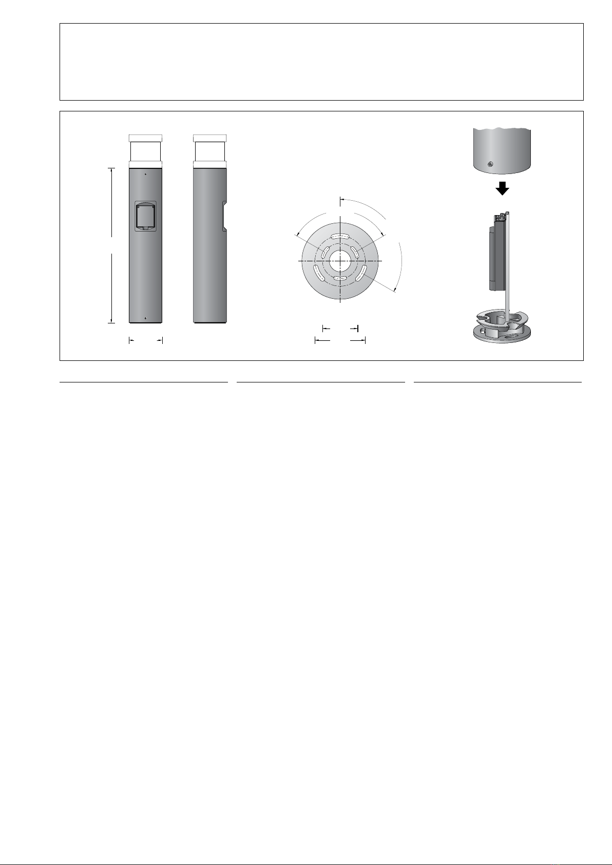
Der Fußpunkt der Leuchte darf nicht tiefer als
die Oberkante des Bodenbelags liegen.
Für den elektrischen Anschluss der Leuchte
ist eine Kabellänge von etwa 400 mm über
Befestigungsgrund ausreichend.
Schraube am Fußpunkt lösen. Montageplatte
drehen und entnehmen.
Bei Montage auf einem Fundament bitte
beachten: Feuchter Beton kann stark alkalisch
sein und darf nicht dauerhaft mit der Leuchte in
Kontakt kommen.
Wir empfehlen den Montagebereich zu
drainieren und mit Isolieranstrich zu versehen.
Montageplatte mit beiliegendem oder
anderem geeigneten Befestigungsmaterial
auf ein Fundament oder Erdstück 70 894
anschrauben.
Pollerleuchtenkopf in das Pollerleuchtenrohr
einsetzen, rechtsherum bis zum Anschlag
drehen, ggf. ausrichten und mit seitlicher
Innensechskantschraube festsetzen.
Anschlusskasten öffnen.
Erdkabel in den Anschlusskasten führen.
Schutzleiterverbindung herstellen und
elektrischen Anschluss vornehmen.
Steckdosen- und Leuchtenanschlussleitung
durch die oberen Leitungseinführungen in den
Anschlusskasten führen.
Schutzleiterverbindung herstellen und
elektrischen Anschluss vornehmen.
Dabei auf richtige Belegung der
Anschlussleitungen achten.
Anschluss der braunen Ader von der Schutz-
kontaktsteckdose an der Klemme L2 (16 A).
Sicherung und Fehlerstrom-Schutzschalter
sind in der Unterverteilung vorzuschalten.
Anschluss der braunen Ader vom Poller-
leuchtenkopf an der Klemme L1 (6 A).
Zur digitalen Ansteuerung des Pollerleuchten-
kopfes sind die beiden losen, mit DALI gekenn-
zeichneten Steckklemmen zu verwenden.
Bei Nichtbelegung dieser Adern wird die
Leuchte mit voller Lichtleistung betrieben.
Anschlusskasten schließen.
Leuchte in die Montageplatte einsetzen, drehen
und mit Schraube festsetzen.
Installation
The luminaire foot must not be below the upper
edge of the oor covering.
Approximately 400mm of cable above the
mounting surface will sufce for connecting the
luminaire to the power supply.
Undo the screw at the base.
Rotate and remove the mounting plate.
In case of installation on a foundation, please
observe the following: Wet concrete can be
highly alkaline and must not come into contact
with the luminaire permanently.
We recommend draining the installation area
and painting it with insulating paint.
Using the provided mounting materials or
other suitable mounting materials, screw-t the
mounting plate to a foundation or anchorage
unit 70 894.
Insert bollard head into bollard tube and turn it
clockwise as far as it will go, adjust if necessary
and x with lateral hexagon socket head screw.
Open the connection box.
Lead the mains supply cable into the
connection box. Make earth conductor
connection and electrical connection.
Pass the luminaire power supply cable through
the top cable entry into the connection box.
Make the earth conductor connection and the
electrical connection.
Note correct conguration of the mains supply
cables.
Connection of the brown wire from the safety
socket outlet to the terminal L2 (16 A). In the
subsidiary distribution the circuit must be
protected by fuses and residual current circuit
breaker.
Connection of the brown wire from the bollard
head to the terminal L1 (6 A). For digital control
of the bollard head please use the two loose
plug-in terminals marked with DALI.
If these wires are not assigned, the luminaire
will work with full light output.
Close the connection box.
Place luminaire onto mounting plate, align and
x with screw.
Installation
Le pied du luminaire ne doit pas se trouver en
dessous du bord supérieur de la couche de
nition du sol.
Pour le raccordement électrique du luminaire
une longueur de câble d’environ 400 mm
au-dessus du sol est sufsante.
Desserrer la vis du pied de la balise.
Tourner et retirer la contre-plaque de la platine.
Attention : En cas d’installation sur un massif
de fondation: La laitance du béton peut être
fortement alcaline et ne doit pas être en
contact durable avec le luminaire. La surface
où le luminaire est installé doit être draînée et
protégée par une matière isolante.
Visser la contre-plaque avec le matériel de
xation fourni ou tout autre matériel approprié
sur un massif de fondation ou sur une pièce à
enterrer 70 894.
Installer la tête de la balise dans le support
de la balise et tourner vers la droite jusqu’à la
butée, ajuster le cas échéant puis xer avec la
vis à six pans creux latérale.
Ouvrir la boîte de connexion.
Introduire le câble réseau dans la boîte de
connexion à travers l’entrée de câble. Mettre à
la terre et procéder au raccordement électrique.
Introduire le câble du luminaire dans la boîte de
connexion par l’entrée de câble supérieure.
Mettre à la terre et procéder au raccordement
électrique.
Veiller au bon adressage du câbles de
raccordement.
La gaine marron de la prise de courant système
allemand doit être raccordée au bornier libre L2
(16 A). Dans la sous-distribution les fusibles et
le différentiel sont à installer en amont.
La gaine marron de la tête de balise doit être
raccordée au bornier L1 (6 A). Pour le contrôle
numérique de la tête de balise, utiliser les deux
bornes à ches libres signalées par la mention
DALI. Si ces ls ne sont pas raccordés, le
luminaire fonctionne sur la puissance maximale.
Fermer la boîte de connexion.
Poser le luminaire sur la contre-plaque, tourner
et xer avec la vis.
Wartung und Prüfung
Elektrische Anlagen und Betriebsmittel
sind nach den anerkannten Regeln der
Elektrotechnik in einem ordnungsgemäßen
Zustand zu erhalten.
Wiederkehrende Prüfungen sind nach
den nationalen Sicherheitsvorschriften
vorzunehmen.
Die Funktionsprüfung des Fehlerstrom-
Schutzschalters in der Unterverteilung sollte
mindestens einmal pro Halbjahr durch
Drücken der Prüftaste Tdurchgeführt
werden, sofern nicht andere regionale oder
anwenderspezische zusätzliche Prüfungen
vorgegeben sind.
Maintenance and Inspection
Electrical installationsandequipment have to
be maintained according to approved electrical
regulations only.
Regular inspections must be carried out
according to national safety regulations.
Correct operation of the residual-current
circuit-breaker in the subsidiary distribution
should be tested at least once every six months
by pressing the test button T, unless other
regional or user-specic tests are required in
addition.
Maintenance et contrôle
Lesinstallationset équipementsélectriques
doivent être maintenues en parfait état
conformément aux règles en usage.
Des contrôles réguliers doivent être effectués
selon les normes nationales de sécurité.
Le contrôle fonctionnel du disjoncteur
différentiel dans la sous-distribution doit être
effectué au moins une fois par semestre en
appuyant sur la touche de contrôle T, dans
la mesure où d’autres contrôles régionaux ou
spéciques à l’utilisateur ne sont pas xés.
Reinigung · Pege
Leuchte regelmäßig mit lösungsmittelfreien
Reinigungsmitteln von Schmutz und
Ablagerungen säubern.
Dafür keinen Hochdruckreiniger verwenden.
Cleaning · Maintenance
Clean luminaire regularly with solvent-free
cleansers from dirt and deposits.
Do not use high pressure cleaners.
Nettoyage · Entretien
Nettoyer régulièrement le luminaire et le
débarrasser des dépôts et des souillures.
Ne pas utiliser de nettoyeur haute pression.
BEGA Gantenbrink-Leuchten KG · Postfach 31 60 · 58689 Menden · info@bega.com · www.bega.com
Bitte beachten Sie:
Installation nur durch Personen mit
einschlägigen elektrotechnischen Kenntnissen
und Erfahrungen! *)
Durch eine unsachgemäße Installation
gefährden Sie:
• Ihr eigenes Leben
• Das Leben der Nutzer der elektrischen
Anlage
Mit einer unsachgemäßen Installation riskieren
Sie schwere Sachschäden, z. B. durch Brand.
Es droht für Sie die persönliche Haftung bei
Personen- und Sachschäden.
Wenden Sie sich sich an einen
Elektroinstallateur!
*) Erforderliche Fachkenntnisse für die
Installation
Für die Installation sind insbesondere folgende
Fachkenntnisse erforderlich:
• die anzuwendenden „5 Sicherheitsregeln“:
Freischalten; Gegen Wiedereinschalten
sichern; Spannungsfreiheit feststellen;
Erden und kurzschließen; benachbarte,
unter Spannung stehende Teile abdecken
oder abschranken
• Auswahl des geeigneten Werkzeuges,
der Messgeräte und ggf. der persönlichen
Schutzausrüstung
• Auswertung der Messergebnisse
• Auswahl des Elektro-Installationsmaterials
zur Sicherstellung der Abschalt-
bedingungen
• IP-Schutzarten
• Einbau des Elektroinstallationsmaterials
• Art des Versorgungsnetzes (TN-System,
TT-System) und die daraus folgenden
Anschlussbedingungen (klassische
Nullung, Schutzerdung, erforderliche
Zusatzmaßnahmen etc.)
Ergänzungsteile
70 894 Erdstück
Erdstück mit Befestigungsansch aus
feuerverzinktem Stahl. Gesamtlänge 400 mm.
3 Befestigungsschrauben M 6 aus Edelstahl.
Teilkreis ø 70 mm.
Accessories
70 894 Anchorage unit
Anchorage unit with mounting ange made
of galvanised steel. Total length 400 mm.
3 stainless steel xing screws M 6.
Pitch circle ø 70 mm.
Accessoires
70 894 Pièce à enterrer
Pièce à enterrer avec asque de xation en
acier galvanisé. Longueur totale 400 mm.
3 vis de xation M 6 en acier inoxydable
sur un cercle de ø 70 mm.
Ersatzteile
Montageplatte 22 002 932 L
Schutzkontaktsteckdose 63 000 569
Spares
Mounting plate 22 002 932 L
Safety socket outlet 63 000 569
Pièces de rechange
Contre-plaque 22 002 932 L
Prise de courant 63 000 569

Other BEGA Outdoor Light manuals

BEGA 84 240 Manual

BEGA

BEGA 84 240 Manual

BEGA 88 490 User manual

BEGA

BEGA 88 490 User manual

BEGA 84 314 User manual

BEGA

BEGA 84 314 User manual

BEGA 98 019 Manual

BEGA

BEGA 98 019 Manual

BEGA 84 422 User manual

BEGA

BEGA 84 422 User manual

BEGA 84 121 User manual

BEGA

BEGA 84 121 User manual

BEGA 55013 User manual

BEGA

BEGA 55013 User manual

BEGA 99 635 User manual

BEGA

BEGA 99 635 User manual

BEGA 84 061 Manual

BEGA

BEGA 84 061 Manual

BEGA 77 138 User manual

BEGA

BEGA 77 138 User manual

BEGA 84 423 User manual

BEGA

BEGA 84 423 User manual

BEGA 98 006 Manual

BEGA

BEGA 98 006 Manual

BEGA 84 991 User manual

BEGA

BEGA 84 991 User manual

BEGA 84 991 Series User manual

BEGA

BEGA 84 991 Series User manual

BEGA 84 020 User manual

BEGA

BEGA 84 020 User manual

BEGA 44 009 User manual

BEGA

BEGA 44 009 User manual

BEGA 33 200 Manual

BEGA

BEGA 33 200 Manual

BEGA 71 128 Manual

BEGA

BEGA 71 128 Manual

BEGA 88 415 User manual

BEGA

BEGA 88 415 User manual

BEGA 84 700 User manual

BEGA

BEGA 84 700 User manual

BEGA 84 427 User manual

BEGA

BEGA 84 427 User manual

BEGA 22 203 Manual

BEGA

BEGA 22 203 Manual

BEGA 22 228 Manual

BEGA

BEGA 22 228 Manual

BEGA 33 160 Series User manual

BEGA

BEGA 33 160 Series User manual

Popular Outdoor Light manuals by other brands

Thorn AVENUE W300 II quick start guide

Thorn

Thorn AVENUE W300 II quick start guide

RAB Design WL-LED26 installation instructions

RAB Design

RAB Design WL-LED26 installation instructions

Maxim Lighting 41425WGBK manual

Maxim Lighting

Maxim Lighting 41425WGBK manual

Nature Power 21035 owner's manual

Nature Power

Nature Power 21035 owner's manual

Dyson Lightcycle CD05 operating manual

Dyson

Dyson Lightcycle CD05 operating manual

Wetelux 75 40 36 instruction manual

Wetelux

Wetelux 75 40 36 instruction manual

Meyer Fluxa C 8 277 1.8 Mounting instructions

Meyer

Meyer Fluxa C 8 277 1.8 Mounting instructions

MAXSA 43319 Assembly and Instruction Guide

MAXSA

MAXSA 43319 Assembly and Instruction Guide

Xterior MICRO FACET LED INSTALLATION, CLEANING AND MAINTENANCE

Xterior

Xterior MICRO FACET LED INSTALLATION, CLEANING AND MAINTENANCE

LightPro Barite 40 112P user manual

LightPro

LightPro Barite 40 112P user manual

Soltech CEGONIA 8W installation manual

Soltech

Soltech CEGONIA 8W installation manual

ABBA CDPA66 installation guide

ABBA

ABBA CDPA66 installation guide

Philips 169289316 user manual

Philips

Philips 169289316 user manual

One Stop Gardens 56680 Owner's manual & safety instructions

One Stop Gardens

One Stop Gardens 56680 Owner's manual & safety instructions

RAB Design ORA-LED instructions

RAB Design

RAB Design ORA-LED instructions

Alice's Garden CUBO 40 POP manual

Alice's Garden

Alice's Garden CUBO 40 POP manual

LIGMAN AUGUSTA 10 installation manual

LIGMAN

LIGMAN AUGUSTA 10 installation manual

iGuzzini AGORA X829 manual

iGuzzini

iGuzzini AGORA X829 manual

manuals.online logo
manuals.online logoBrands
  • About & Mission
  • Contact us
  • Privacy Policy
  • Terms and Conditions

Copyright 2025 Manuals.Online. All Rights Reserved.