manuals.online logo
Brands
  1. Home
  2. •
  3. Brands
  4. •
  5. BERMAD
  6. •
  7. Control Unit
  8. •
  9. BERMAD BC-710-P User manual

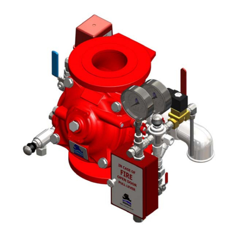
BERMAD BC-710-P User manual

File Name: IOM BC-710-P (1.5in
–
8in) Rev. 00 Prepared By: RC Date: 06/17
engineering@vbtech.com ●www.vbtech.com ●www.bermad.com
The information contained in this document is subject to change without notice. BERMAD shall not be liable for any errors
contained herein. All Rights Reserved. © Copyright BERMAD Control Valves.
Model BC-710-P IOM
Solenoid Controlled Valve
Description
The Model BC-710-P Solenoid Controlled Valve opens and closes in response to an electrical signal. When solenoid 15 is signaled
to open the main valve, the solenoid vents the cover chamber to atmosphere. When solenoid 15 is signaled to close the main valve,
upstream pressure is applied to the cover chamber, closing the valve drip-tight.
Installation
1. Allow enough room around the valve assembly for making adjustments and for future maintenance and disassembly work.
2. Thoroughly flush the pipeline to remove dirt, scale, and debris. Failure to perform this operation may render the valve inoperable.
3. It is recommended that isolation valves be installed upstream and downstream of the Bermad pressure reducing system to allow for
future maintenance operations.
4. Install the valve in the pipeline with the valve flow arrow on the body casting in the proper direction. Install the valve horizontally with
the cover up for best performance. Make certain the valve is positioned so the cover assembly can be easily removed for future
maintenance requirements.
5. System power connections, control cabinet, controller, sensors & wiring should be carried out by authorized electrical engineer /
electrician and comply with all relevant electrical codes.
6. Check the solenoid specification and the markings on the side of the coil to verify proper voltage of coil (i.e. 120/60=120VAC). This
is to prevent coil/solenoid burn-out.
7. Connect the power cables to the solenoid. The solenoid has three connections, one which is either a green/yellow wire or marked
with the grounding symbol, this is an earth ground or conduit ground wire for safety precautions. The other two connections are
power/’hot’ and common, or negative on DC systems. These two connections have no polarity, so either wire can be used for
power/common. Do not apply power to the ground connection or it will burn the solenoid and/or coil. Note: There must be at least
85% of the voltage stamped on the side of the coil at the solenoid splice, not controller, for the solenoid to function properly.
8. If applicable, run the appropriate conduit and cables to wire a limit switch or position transmitter. See relevant accessories IOM for
more information.
9. After installation carefully inspect/correct any damaged accessories, piping, tubing, or fittings.
Commissioning & Calibration
There must be sufficient flow through the valve and system to check and adjust the valve. Insure that a downstream demand is created.
Ball valve 1 must be open at all times for the valve to operate.
1. Fully open the upstream isolation valve and partially open the downstream isolation valve, to fill the consumer line downstream of
the valve, in a slow and controlled manner.
2. Confirm that the supply pressure and the flow through the system are typical. If necessary, create flow by opening a hydrant, or
reduce the flow/pressure by adjusting the downstream/upstream isolation valves.
3. If a limit switch is installed, set the limit switch cam to activate the limit switch when the 710 is in the fully closed position. The signal
should trigger an alarm in the Building Management System.
4. The Model BC-710-P has two common configurations:
4.1. Normally Closed Valve, with a Normally Open Solenoid. In this configuration, energizing the solenoid will vent the cover
chamber to atmosphere, causing the main valve to open.
4.2. Normally Open Valve, with a Normally Closed Solenoid. In this configuration, energizing the solenoid will apply line pressure to
the cover chamber, causing the main valve to close.
5. Cycle the valve open and closed to verify valve operation.
6. Fully open the upstream and downstream isolation valves, if they are not already.
File Name: IOM BC-710-P (1.5in
–
8in) Rev. 00 Prepared By: RC Date: 06/17
engineering@vbtech.com ●www.vbtech.com ●www.bermad.com
The information contained in this document is subject to change without notice. BERMAD shall not be liable for any errors
contained herein. All Rights Reserved. © Copyright BERMAD Control Valves.
Model BC-710-P IOM
Vent
700
P
A/B
15
R
Vent
1
4
Control Loop Diagram
Troubleshooting
Symptom Possible Cause Solution
Valve Fails to Open Insufficient inlet pressure.
No downstream demand.
Solenoid 15 is signaled to close the main
valve.
Check/create inlet pressure.
Create demand/flow
Energize or de-energize the solenoid as
necessar
y
.
Valve Fails to Close
*CAUTION: Valve will be fully open. Close
the downstream isolation valve or omit this
test if this condition may cause system
damage.
Filter 4 plugged/clogged.
Ball valve 1 is closed.
Solenoid 15 is signaled to open the main
valve.
Debris trapped in main valve.
* Diaphragm in main valve leaking or
diaphragm assembly loose.
Open filter 4 and clean screen.
Open ball valve 1.
Energize or de-energize the solenoid as
necessary.
Remove actuator assy. to inspect seat

area/verify valve stroke/remove debris.
*After closing ball valve 1, remove small
plug at valve cover. Continuous flow
indicates diaphragm leakage. Inspect,
tighten, and/or
r
eplace Diaphragm.
PART LIST
1 Inlet Ball Valve, Normally Open
4 Control Filter
15 3-Way Solenoid
700 Main Valve

Other BERMAD Control Unit manuals

BERMAD 430 User manual

BERMAD

BERMAD 430 User manual

BERMAD C10 User manual

BERMAD

BERMAD C10 User manual

BERMAD 435 User manual

BERMAD

BERMAD 435 User manual

BERMAD 420 Guide

BERMAD

BERMAD 420 Guide

BERMAD 410-01-3NC-200 User manual

BERMAD

BERMAD 410-01-3NC-200 User manual

BERMAD 700 Series User manual

BERMAD

BERMAD 700 Series User manual

BERMAD 430-Z-3W Owner's manual

BERMAD

BERMAD 430-Z-3W Owner's manual

BERMAD FP 430-UF Owner's manual

BERMAD

BERMAD FP 430-UF Owner's manual

BERMAD 400E-Y General instructions

BERMAD

BERMAD 400E-Y General instructions

BERMAD 720 User manual

BERMAD

BERMAD 720 User manual

BERMAD C15 User manual

BERMAD

BERMAD C15 User manual

BERMAD 400E-5D Owner's manual

BERMAD

BERMAD 400E-5D Owner's manual

BERMAD 730-UF Owner's manual

BERMAD

BERMAD 730-UF Owner's manual

BERMAD BC-73Q-P User manual

BERMAD

BERMAD BC-73Q-P User manual

BERMAD K10 User manual

BERMAD

BERMAD K10 User manual

BERMAD 450-66-Z User manual

BERMAD

BERMAD 450-66-Z User manual

BERMAD C80 Instruction manual

BERMAD

BERMAD C80 Instruction manual

BERMAD 400 Series User manual

BERMAD

BERMAD 400 Series User manual

BERMAD FP-3HC-0 Instruction manual

BERMAD

BERMAD FP-3HC-0 Instruction manual

BERMAD C30 User manual

BERMAD

BERMAD C30 User manual

BERMAD 42T Owner's manual

BERMAD

BERMAD 42T Owner's manual

BERMAD 450-60 User manual

BERMAD

BERMAD 450-60 User manual

Popular Control Unit manuals by other brands

Thermo Scientific Smart-Vue installation manual

Thermo Scientific

Thermo Scientific Smart-Vue installation manual

hilscher COM-C Series Design guide

hilscher

hilscher COM-C Series Design guide

DSEGenset DSE7410 manual

DSEGenset

DSEGenset DSE7410 manual

Sporlan Parker S3C Startup guide

Sporlan

Sporlan Parker S3C Startup guide

Gira 1283 00 Mounting instructions

Gira

Gira 1283 00 Mounting instructions

ARRI RF-EMIP operating manual

ARRI

ARRI RF-EMIP operating manual

GSM OUT MiniModul user manual

GSM

GSM OUT MiniModul user manual

WEG SSW07 Series installation guide

WEG

WEG SSW07 Series installation guide

Rabbit RabbitCore RCM3000 user manual

Rabbit

Rabbit RabbitCore RCM3000 user manual

ICP DAS USA ZT-2017 user manual

ICP DAS USA

ICP DAS USA ZT-2017 user manual

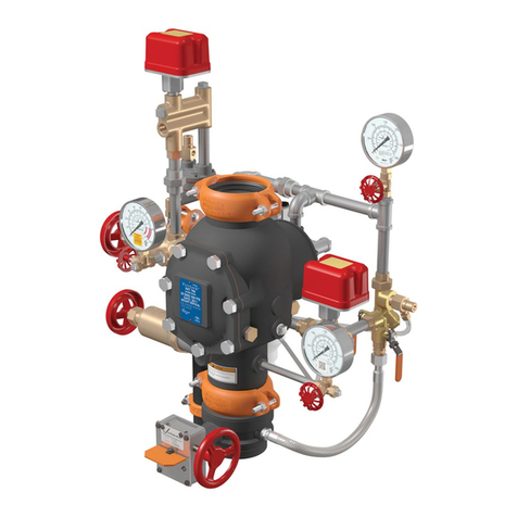
Victaulic FireLock NXT 769N Series Installation, Maintenance, and Testing Manual

Victaulic

Victaulic FireLock NXT 769N Series Installation, Maintenance, and Testing Manual

Emerson XJ200 Installation and operating instructions

Emerson

Emerson XJ200 Installation and operating instructions

VAT 653 Series Installation, operating,  & maintenance instructions

VAT

VAT 653 Series Installation, operating, & maintenance instructions

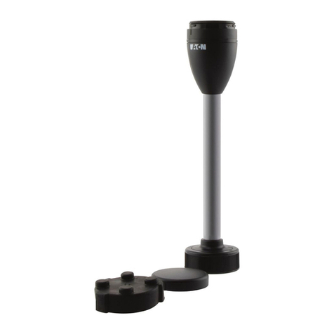
Eaton SL4-FMS Series Instruction leaflet

Eaton

Eaton SL4-FMS Series Instruction leaflet

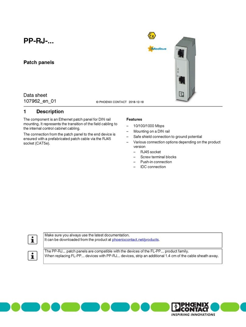
Phoenix Contact PP-RJ Series datasheet

Phoenix Contact

Phoenix Contact PP-RJ Series datasheet

ALLEN & HEATH Qu-24 reference guide

ALLEN & HEATH

ALLEN & HEATH Qu-24 reference guide

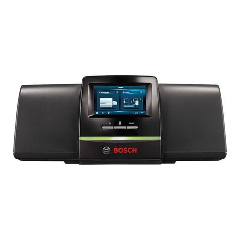
Bosch Control 8313 Operating instructions for users

Bosch

Bosch Control 8313 Operating instructions for users

Deif GCU 100 Operator's manual

Deif

Deif GCU 100 Operator's manual

manuals.online logo
manuals.online logoBrands
  • About & Mission
  • Contact us
  • Privacy Policy
  • Terms and Conditions

Copyright 2025 Manuals.Online. All Rights Reserved.