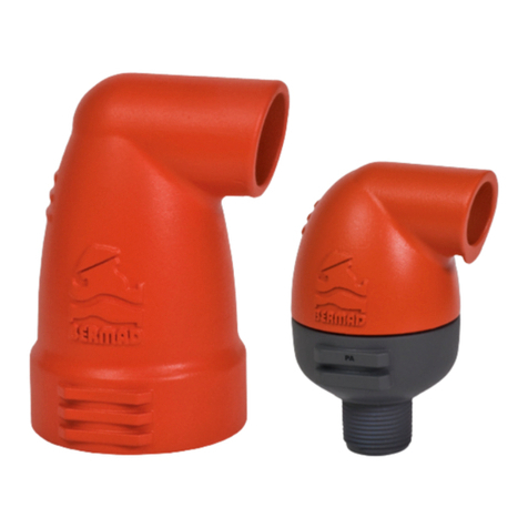
BERMAD C80 Instruction manual

1
NON-CLEAN, SEWAGE & WASTEWATER
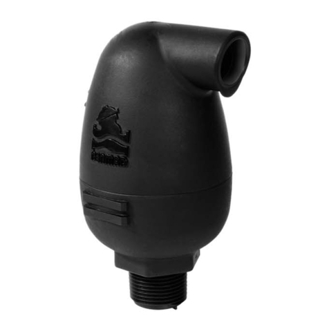
COMBINATION AIR VALVE
Model C80
Installation, Operation & Maintenance Manual (IOM)

2
Table of Contents
Introduction ......................................................................................................................................................................4
Safety First ........................................................................................................................................................................4
General..........................................................................................................................................................................4
Unpacking, Shipping, handling and installing the air valve...........................................................................................4
Maintenance.................................................................................................................................................................5
Pre-Installation Requisites ................................................................................................................................................6
Post Shipment...............................................................................................................................................................6
Site Preparation ............................................................................................................................................................6
Installation Instructions ....................................................................................................................................................7
Adding Additional Feature to the C80 Air Valve...............................................................................................................9
First startup.....................................................................................................................................................................10
Operation and Monitoring..............................................................................................................................................11
Quick maintenance .........................................................................................................................................................12
Periodic maintenance .....................................................................................................................................................14
Troubleshooting..............................................................................................................................................................19
Disassembling the air valve.............................................................................................................................................19
Reassembly and returning to service..............................................................................................................................26
BOM Drawings and tables...............................................................................................................................................31
Spare parts list ................................................................................................................................................................33
Bermad Standard International Limited Warranty.........................................................................................................35
IOM Bermad Disclaimer..................................................................................................................................................36

3
Table of Figures
Figure 1 - Installation options ...........................................................................................................................................8
Figure 2 –SP Picture .........................................................................................................................................................9
Figure 3 - AC Picture..........................................................................................................................................................9
Figure 4 - IP Picture.........................................................................................................................................................10
Figure 5 - Quick flush ......................................................................................................................................................13
Figure 6 - Periodic maintenance A..................................................................................................................................14
Figure 7- Periodic maintenance B...................................................................................................................................15
Figure 8 - Periodic maintenance C ..................................................................................................................................15
Figure 9 - Periodic maintenance D..................................................................................................................................16
Figure 10 - Periodic maintenance E ................................................................................................................................16
Figure 11 - Replacing the seals - A ..................................................................................................................................17
Figure 12 - Replacing the seals - B ..................................................................................................................................17
Figure 13 - Replacing the seals - C ..................................................................................................................................18
Figure 14 - Disassembling the air valve - A .....................................................................................................................20
Figure 15 - Disassembling the air valve - B .....................................................................................................................21
Figure 16 - Replacing the seals - A ..................................................................................................................................21
Figure 17 - Replacing the seals - B ..................................................................................................................................22
Figure 18- Replacing the seals - B ...................................................................................................................................22
Figure 19 - Replacing the seals - C...................................................................................................................................23
Figure 20 - Replacing the seals - D..................................................................................................................................23
Figure 21 - Replacing the seals - E...................................................................................................................................24
Figure 22 - Versions.........................................................................................................................................................24
Figure 23 - Version A.......................................................................................................................................................25
Figure 24 - Version B.......................................................................................................................................................25
Figure 25 - Reassembling - A...........................................................................................................................................26
Figure 26 - Reassembling - B...........................................................................................................................................26
Figure 27 - Reassembling - C...........................................................................................................................................27
Figure 28 - Reassembling - D...........................................................................................................................................27
Figure 29 - Reassembling - E ...........................................................................................................................................27
Figure 30 - Reassembling - F ...........................................................................................................................................28
Figure 31 - Reassembling - G...........................................................................................................................................28
Figure 32 - Reassembling - H...........................................................................................................................................29
Figure 33 - Reassembling - I ............................................................................................................................................29
Figure 34 - Reassembling - J............................................................................................................................................30
Figure 35 - BOM Version A..............................................................................................................................................31
Figure 36 - BOM Version B..............................................................................................................................................32

4
Introduction
Thank you for purchasing the BERMAD Non-clean, Sewage & Wastewater Combination Air Valve model C80,
which is a high-quality air valve for various Sewage & Wastewater networks and operating conditions. The
C80 evacuates air during pipeline filling, allows efficient release of air and gas pockets from pressurized pipes,
and enables large volume air intake in the event of network draining. The elongated body and lower float
prevent the fluid to be in contact with the upper mechanism.
This document describes the Installation, Operation, and Maintenance of the C80 Air Valve.
Safety First
General
Since air valves operate in pressurized waste water networks and sewage systems with toxic or corrosive environment,
you are required to carefully read this manual before using the valve. Handle the valve with care and make sure to
comply with all the relevant required safety instructions and standards, general and local.
During installation, operation or maintenance of the air valve, use always good engineering practices and avoid danger
to the workers, the public or to property in the vicinity.
Use only standard and approved tools and equipment, operated by qualified operators, when installing, operating and
maintaining the air valve.
Since the air valve is installed in hazardous environment sites and/or underground, make sure that the installation
procedures are carried out in accordance with the relevant standards and regulations.
Never use the product for purpose other than its original design and operation environment.
The workers must comply with the occupational safety and health (OSH) instructions and protect themselves with
personal safety gear such as helmets, goggles, gloves, and any other personal safety equipmentתrequired by the
regulations, while installing, operating, and maintaining the air valve.
Unpacking, Shipping, handling and installing the air valve
Before starting the installation, make sure that the air valve was not damaged during shipment to the site.
Handel the air valve with care in safe and stable way; when lifting and moving it use only approved equipment,
operated by licensed operators.
Carefully comply with the installation process stages described in this IOM document and follow all the relevant safety
instructions.

5
Maintenance
Prior to any maintenance work to be done on the air valve make sure that:
▪Before any maintenance or non-regular operation, close the Isolation / ball valve, which is installed below the
air valve.
▪Comply with and follow all the standards and regulations for handling the fluids on which the air valve is
operated.
▪The work must be done only by professionals trained for this type of work.
▪Slowly open the drainage valve, or the ball valve, located on the lower side of the air valve body, make sure
that the pressure is released; take extra care while releasing the hazardous, high energy, compressed gas.
▪Make sure that the air valve is completely empty from liquids before starting the maintenance process.
▪Disassembling the air valve from the pipeline must be done only after verifying that the internal pressure is
released.
▪Comply with all the local standards and regulations when cleaning of the air valve with water jets or steam,
follow the cleaning instructions and avoid harming people or the environment.
▪Check the air valve’s safety labels (for example the “Non-Drinking” label) and replace them when needed.

6
Pre-Installation Requisites
Post Shipment
Make sure that till the actual installation the valve remains dry and clean in its original package.
▪Unpack the valve and make sure that all the wrapping materials are removed.
▪Before installation it is necessary to inspect that no damage to the valve had occurred during
shipment; do not install a damaged valve!
▪Verify that the valve to be installed meets the design specifications of the specific installation site;
take extra care and make sure that the expected system pressure complies with the pressure rating
of the valve.
▪Make sure that the lifting-eye is tightly connected to the air valve.
Site Preparation
▪Air Valves located above ground should be protected from freezing and vandalism.
▪If the valve is to be installed in a pit, make sure that the pit has proper drainage and sufficient
dimensions for servicing the valve.
▪Flush the pipeline prior to the air valve installation in order to prevent damage to the valve internals
due to large debris carried by the water during startup.

7
Installation Instructions
The usage of air valves is very important for efficient operation of all sewage and wastewater systems’
types; correct Sizing and precise Installation locations of the air valves along the system is crucial for
protecting the system.
This chapter describes only the very basic requirements for air valve installation; for designing the
required number, size and locations of air valves in your system please refer to Bremad’s “Air-Control -
WW-Engineer Guide_v13.pdf” document.
Raiser
▪Install the air valve as close as possible to the pipe, in vertical position (within 5 degrees of vertical
alignment with its inlet facing down).
▪Non-vertical Installation will disturb the regular performance of the air valve. The diameter of the
raiser should be equal or bigger than the diameter of the air valve inlet.
Shutoff valve
▪To allow easy inspection and maintenance of the air valve, a shutoff valve must be installed between
the pipeline and the air valve. During operational mode, this valve has to be fully opened.
Drainage pipeline
▪When required, a drainage pipeline should be fitted to the valve's outlet. The diameter of the
drainage pipeline should be at least equal or bigger than the diameter of the air valve. Smaller
diameter will decrease the air flow capacity of the air valve.
The following pictures depict some typical installations of the C80 air valve (Please refer to Bremad’s “Air-
Control - WW-Engineer Guide_v13.pdf” document):

8
Figure 1 - Installation options

9
Adding Additional Feature to the C80 Air Valve
Surge Protection Device:
Please refer to the following picture for adding a Surge protection device to the C80 Air Valve:
Assisted Closing Device:
Please refer to the following picture for adding an Assisted Closing device to the C80 Air Valve:
1
2
1
2
Figure 2 –SP Picture
Figure 3 - AC Picture

10
Inflow Prevention Device:
Please refer to the following picture for adding an Inflow Prevention device to the C80 Air Valve:
First startup
▪Open the Isolation / ball valve and verify that the air valve connections are not leaking; if needed
follow the troubleshooting instruction section of this document.
▪Please note: At the first time the valve is filled up, some limited quantity of water may exit through
its outlet port.
▪Prevent water hammer during startup and pipeline filling, by maintaining the velocity lower than
0.5m/sec (1.6 feet/sec).
▪It is recommended adding Surge Protection devices in systems where higher velocity is expected.
1
2
3
Figure 4 - IP Picture

11
Operation and Monitoring
Principles of operation
Pipeline filling
During the filling process of a pipeline, high air flow is forced out through the kinetic orifice of the air
valve. Once water enters the valve’s chamber, the float buoyed upwards causes the kinetic orifice to
close. The unique aerodynamic structure of the valve body and float ensures that the float cannot be
closed before water reaches the valve.
Pressurized operation
During pressurized operation of the pipeline, air accumulates in the upper part of the air valve chamber,
causing the float to gravitate downwards. This in turn causes the automatic orifice to open, releasing the
accumulated air. Once the air is discharged, the water level and float rise and the automatic orifice closes.
Pipeline draining
When a pipeline is drained, a negative differential pressure is created, causing atmospheric air to push
the float down. The kinetic orifice stays open and air enters the valve chamber, preventing vacuum
formation in the pipeline.
Surge protection (anti-slam)
The anti-slam device is fitted to the air valve outlet. In the event of a pressure surge it partially closes the
valve’s outlet. The approaching water column decelerates due to the resistance of the rising air pressure
in the valve.
Inflow prevention
The inflow prevention mechanism is a Normally Closed check device fitted on the valve’s outlet and
preventing flow of atmospheric air into the valve.
Important note: avoid getting closer to the air valve’s exhaust opening while vacuum conditions are
present.

12
Monitoring
The air valve is built for operation with sewage and wastewater liquids, that contain foreign objects, oils
and other materials. Therefore, during pumps startup and pipelines filling, check that the air valve reliefs
the large volume of air from the pipelines through its outlet, and admitting large volume of air to the
pipelines during pumps shutdown.
Also, check that the air valve releases small volume of air from its outlet, due to air pockets accumulated
in the pipeline, during regular operation.
Quick maintenance
The C80 air valve’s body has two service ports (upper and lower) that allow the user, when needed and
depend on the dirt-load, to perform a quick flushing of the valve’s internal body (See the following picture):
1. Make sure that you are familiar with all the relevant safety instruction for this type of work; read the
Safety-First chapter of this document.
2. Before any maintenance or non-regular operation, close the Isolation / ball valve, which is installed
below the air valve.
3. Slowly open the drainage valve, or the ball valve, located on the lower side of the air valve body,
make sure that the pressure is released; take extra care while releasing the hazardous, high energy,
compressed gas.
4. Make sure that the air valve is completely empty from liquids before starting the maintenance
process.
5. Connect a pressurized clean water hose to the upper service port of the air valve.
6. Connect a suitable drainage line to the lower service port of the air valve; make sure to comply with
all the relevant safety instructions and regulations required for protecting people and the
environment.
7. Flush the valve by discharging pressurized clean water into its upper service port till clean water exits
through the lower service port.
8. Close the service ports and reopen the isolation valve.

13
Figure 5 - Quick flush
Pressurized
clean water
Proper drainage line

14
Figure 6 - Periodic maintenance A
Periodic maintenance
A periodical inspection of the seals and flushing of the valve are recommended for removing debris,
foreign objects, and grease that might interfered with the regular operation of the air valve.
The valve’s flushing and cleaning frequency depends on sewage and wastewater characteristics and dirt-
load.
The periodic maintenance procedure includes the following stages:
1. Make sure that you are familiar with all the relevant safety instruction for this type of work; read the
Safety-First chapter of this document.
2. Before any maintenance or non-regular operation, close the Isolation / ball valve, which is installed
below the air valve.
3. Slowly open the drainage valve, or the ball valve, located on the lower side of the air valve body,
make sure that the pressure is released; take extra care while releasing the hazardous, high energy,
compressed gas.
4. Make sure that the air valve is completely empty from liquids before starting the maintenance
process.
5. Flush the internal components of the air valve: (See the following pictures.)
•Verify that the pressure is released and the air valve body is empty.
•Using key number 22, unscrew the 4 nuts of the air valve cover assembly.

15
•Pull out the internal assembly of the air valve.
•Using 3/32” Allen key, disconnect the locking screw of the automatic mechanism, and
separate the upper float assembly from the rest of the internal mechanism.
Figure 7- Periodic maintenance B
Figure 8 - Periodic maintenance C

16
•Remove any foreign objects
•Flush and clean the automatic orifice seals
•Flush and clean the kinetic orifice and its seal.
•Check for signs of wear and tear or any damaged parts.
Figure 9 - Periodic maintenance D
Figure 10 - Periodic maintenance E

17
•If needed replace the automatic seal and the kinetic seal.
•Replace the automatic seal: Remove the old seal [A], insert one side of the new seal to its
designated slot [C], insert the other side of the seal to the opposite side slot, and cut the
excessive rubber rods [D].
•Replace the Kinetic seal; unscrew the four bolts, remove the locking ring and replace the
seal
Figure 11 - Replacing the seals - A
A
B
C
D
Figure 12 - Replacing the seals - B

18
•Pull out the seal assembly [A] and replace the seal [B].
•Reassemble the air valve in reverse order.
•Tighten the four side cover bolts to 25 N-m torque.
•Reopen the isolation valve.
If during the periodic maintenance procedure, signs of wear and tear are found on the air valve
components, please refer to the Disassembling the air valve chapter of this document.
Figure
13
- Replacing the seals - C
A
B

19
Troubleshooting
Symp
t
om
Action
Leakage
at the
inlet
connection
Tighten
the
valve inlet
connection, use thread
sealant.
Check whether any
part/seal
is damaged.
Leakage
from the connection between
the
valve’s
cover and body
Tighten
the
valve’s
cover
Leakage
at
the
valve’s
outlet
Close the isolation valve. Then, at first, connect a clean water
pipe to the upper service port of the valve and open its
drainage valve. Flush
the
valve
to
remove
debris.
In case the symptom remains,
dissemble
and inspect the
valve’s orifices, floats and
seals.
Remove
any
foreign
objects, clean the orifices and seals. Check and
replace
any damaged part.
Valve
does not
release
air or
allow
air intake
Verify
that the
operating
pressure does not exceed the
valve’s
rated working pressure.
Check and
remove foreign
objects.
Clean
the
valve’s
internal
parts,
replace
if necessary.
Consult Bermad if the symptom continues.
Disassembling the air valve
Perform the following stages when a complete disassembly of the air valve is required:
1. Make sure that you are familiar with all the relevant safety instruction for this type of work; read the
Safety-First chapter of this document.
2. Before any maintenance or non-regular operation, close the Isolation / ball valve, which is installed
below the air valve.

20
Figure 14 - Disassembling the air valve - A
3. Slowly open the drainage valve, or the ball valve, located on the lower side of the air valve body,
make sure that the pressure is released; take extra care while releasing the hazardous, high energy,
compressed gas.
4. Make sure that the air valve is completely empty from liquids before starting the maintenance
process.
5. Start by removing the air valve cover, pulling out the internal assembly and disconnecting the locking
screw of the upper float assembly. (See the Periodic Maintenance chapter of this document.)
Table of contents
Other BERMAD Control Unit manuals

BERMAD
BERMAD 400 Series User manual

BERMAD
BERMAD C30 User manual

BERMAD
BERMAD 450-60 User manual

BERMAD
BERMAD BC-710-P User manual

BERMAD
BERMAD 400E-5D Owner's manual

BERMAD
BERMAD FP 430-UF Owner's manual

BERMAD
BERMAD FP-3HC-0 Instruction manual

BERMAD
BERMAD K10 User manual

BERMAD
BERMAD 400E-Y General instructions

BERMAD
BERMAD 410-01-3NC-200 User manual
Popular Control Unit manuals by other brands

Flomatic
Flomatic Comboair installation instructions

H. B. Fuller
H. B. Fuller Cyberbond CB LINOP U 500 operating instructions

Crane
Crane NOZ-CHEK Cryogenic Operation and maintenance instruction

Flowserve
Flowserve atomac AKH7 Series Technical manual

Siemens
Siemens TL-30U installation instructions

APV
APV SLP Installation, operation & maintenance manual