BERMAD 700 Series User manual

CELESCO POTENTIOMETER
INSTALLATION—700 SERIES CONTROL
VALVES
1- 1/2 IN-32 IN
SIZES
4070 LEAVERTON COURT ANAHEIM, CA. 92807 USA
BERMAD

Disassembly I– INITIALLY, SEE FIGURE 00 ON PAGE 6 TO MAKE SURE THAT THE POTENTIOMETER PART#
MATCHES AND CORRESPONDS TO THE RIGHT SIZE VALVE OR CALIBRATION WILL NOT BE ABLE TO BE
ACCOMPLISHED. USE ALL FIGURES 0-4 AS A VISUAL AID TO GUIDE THROUGH INSTALLATION/
CALIBRATION.
1d. De-pressurize the system and isolate the main valve from the rest of the system by shutting gate/butterfly valves up and
downstream. Shut all cock valves that feed the control loop, pilots, solenoids and devices.
2d. There must be enough room to insert the potentiometer (1) RT9420 and its mounting bracket (8) accessories to the main valve
cover. There must also be enough room for adjustment to zero ‘Z’ and span ‘S’ adjusting screws for fine tuning (FIG. 1). If
disassembly of tubing or parts are necessary to add the potentiometer (1) and bracket (8), tag all plumbing connections noting
pilot/solenoid port numbers for proper reassembly. Remember that there is still static pressure in the pipeline and in the main
valve cover and accessories.
3d. Carefully remove a control tube from the cover or loosen the large top cover plug (5B) of the main valve slowly until all
pressure is relieved from the cover. (FIG 0). CAUTION! Do not take the cover plug completely out of the cover until all
pressure is drained from the cover or serious injury or death could result. If the line pressure does not drop, a leaking
isolation valve could be at fault. This must be taken into consideration due to the complete de-pressurization needed to set the
potentiometer (1) in a closed valve position to set properly causing a nuisance and inaccurate settings.
4d. The principal objective is to get the valve shut and to leave it shut to be able to set the potentiometer (1). Follow the main
valve static tests to get the main valve to close or have some available auxiliary pressure source available (i.e. bicycle pump, hose,
etc... ) to pressurize the top chamber to get the valve in a closed position. All main valves that have an internal spring, like main
valve 705 or 700-Q, will go closed automatically when the line is completely de-pressurized upstream and downstream of the
main valve.
PROCEDURES TO INSTALL THE RT9420 POTENTIOMETER TO THE 700 SERIES BASIC CONTROL VALVE
Page 1
700 SERIES VALVE
CAUTION WHEN VENTING PRESSURE!!!
FIG. 0
MAIN COVER PLUG
BOOM!

Inspection/Assembling
1. Clean the cover plug hole of any debris or build-up of organics and inspect the indicator locknut which can be seen when
looking down into the cover plug hole (FIG. 0&4). The indicator locknut (19) has a hole and either a tapered slot or machined
recess in the middle of it. Inspect it for corrosion and serviceability. Make sure that it is tight. If it is not, add several drops of
Loctite thread-lock compound into the middle hole and tighten it clockwise (FIG 4).
2. Determine the bracket (8) position that the potentiometer (1) will be mounted. Inspect all fittings on the cover for
discoloration, breaks or possible leak points. Replace the fitting(s) if necessary. A fitting may have to be moved or another
choice of fitting/tube may have to be retro-fitted to accommodate the bracket-potentiometer assembly. There are three
available choices to plumb a fitting into the cover or a tee may be added to adapt two fittings to one cover plug hole (FIG. 1&2).
The cover taps can be cleaned with with a wire bore brush. Retap the hole with the proper NPT-tap. This procedure is a must for
valves in service for several years in aggressive water and heavy-duty applications.
3. Make sure the two small o-rings (43) are in the I.D of the indicator cover plug (46) and that there is an o-ring under the lip
on the O.D of the cover plug (59 and/or 41—FIG. 4) . Lubricate them liberally with a light grease or o-ring lubricant. Install the
e-clip (44) into the grooved recess at the bottom of the indicator rod (48) by pushing the rod (48) into the open end of the e-clip
(44). Tilt the rod (48) at an angle against the side of the cover hole bore and push it into the indicator locknut plug’s machined
center hole (FIG. 4). On the older models, it may be necessary to tap the rod (48) in at an angle to get the rod (48) into the
indicator locknut (19). Stand it straight up in its center position within the cover hole and slide the indicator cover plug(s) (46
and/or 47– FIG. 4) onto the rod (48) taking care not to damage o-rings (43). This should happen with little force. Continue to
thread and tighten the indicator cover plug(s) (46 and/or 47-FIG.4) clockwise until it is tight The indicator rod (48) should spin
freely but not be able to be pulled up out of the indicator locknut (19) assembly. If it can be moved up and down, the indicator
cover plug must be removed for inspection, then repeat installation steps. If it happens again, the indicator locknut (19) could be
worn or corroded. A new indicator locknut (19) should be ordered to replace the old one and assembled with a thread-locker
compound (Loctite).
4. Continue to assemble the potentiometer assembly leaving the lever arm adjustment screw (4) and
collar adjustment screw (4A) loose enough to set the potentiometer ranges. Refer to figures 1 and 2 in
this manual for further details, assembly and placement of each component.
PROCEDURES TO INSTALL THE RT9420 POTENTIOMETER TO THE 700 SERIES BASIC CONTROL VALVE
Page 2

Set-Up Calibration
1. Assemble the potentiometer (1) and bracket assembly leaving the lever arm and collar adjusting screws (4&4A– FIG.2
loose for later calibration adjustments. A 5 /64” allen tool is needed to loosen or tighten adj. screws. The objective is to have
the valve fully stroke open and closed without binding within the collar (8) that rides on the indicator rod (48). See the full
stroke of the valve according to the size on figures 1 & 2 for the total valve stem travel. The entire bracket assembly
arrangement may have to be moved or turned slightly or the lever arm (3) may have to be either moved in or away from the
main potentiometer body (1) to prevent the lever arm roller from binding within the collar (8). After finding the best mounting
position and not having the lever arm (3) bind throughout the stroke of the valve, slightly tighten the collar adjusting screw (4A)
just enough so the collar (8) will stay set and not move easily during calibration.
2. The important measuring device that is used to calibrate this potentiometer is the multi-meter or ammeter. See description
on figure 3. Generally, a multi-meter is an ammeter, voltmeter, ohmmeter and sometimes even a thermocouple temperature
reading device all in one meter. There are plain ammeters also on the market which can be used but the multi-meter is the most
commonly found at auto part, electronic and even some general stores in an automotive section. The set up in figure 3 displays a
common multi-meter. There are many different types of multi-meters on the market today; however, any meter that has a DC
milliamp (DC mA) measuring capabilities will suffice. The setting on the multi-meter must be on milliamps or a setting to read
4-20 mA (usually the lowest setting) which should be stamped on the meter face or just plainly stamped mA on the direct
current-DC mA setting. Do not set on the alternating current AC mA settting or it will give erroneous readings. Some meters
will not be stamped AC or DC. Instead they will have a sine wave symbol for AC power and symbol
for DC current. Remember that the potentiometer (1) works on DC current only and it must have a voltage to pin A of at least
12 volts DC (VDC) and no more than 40 volts DC (VDC).
3. Purchase two brand new 9-volt high-quality alkaline batteries (i.e. Duracell) and hook them in series as shown in figure 3.
It is highly suggested to buy the electric materials at a specialized electronic store (i.e. Radio Shack) since they will have the
field-service items that are needed to calibrate this potentiometer. It is best to use long alligator-type clips with insulated covers
to make all the connections tight and to not give erroneous readings on the meter screen. If necessary,
long light gauge wire of 18 A.W.G can be used if long runs of wire is needed in between components
in tight valve vaults or cramped quarters. Connect the clips, runs of wire and meter lead connections
as shown in figure 3. It is extremely important to not let any of the bare metal connections at any
splice to touch any metal conductor like the valve body, tools or any conductive material.
PROCEDURES TO INSTALL THE RT9420 POTENTIOMETER TO THE 700 SERIES BASIC CONTROL VALVE
Page 3

Set-Up Calibration (Continued)
This could not only give an erroneous reading at the multi-meter but could possibly damage the meter or the potentiometer (1). It is
important to not let the connections between pin A and pin B (FIG. 2) make contact which could short-circuit the reading from the
potentiometer (1). It is highly unlikely that this will damage the potentiometer (1) since there is very low amperage using two 9-volt
batteries, which is the reason for calibrating the potentiometer (1) with these two small battery power sources. Polarity is very
important. Make sure to connect the positive source from the battery to pin A and follow the rest of the connections exactly as
shown in figure 3.
4. The key objective is to get close as possible to 4mA at the closed stroke of the valve and as close to 20mA to a fully open valve.
These procedures are going to guide the calibration as a static-calibration where the valve does not have to be fully stroked open since
the full open valve stroke is known and the valve is already closed to set the low-end of calibration. The high end is going to be set by
using the chart in figures 1 & 2 and moving the collar (8) that exact full open stroke of the valve to calibrate at 20mA. Take the two
screws from the fine tuning adjustment ‘S’ and ‘Z’ ports (FIG.1) on the potentiometer (1) and place them in a safe place.
5. Turn the multi-meter on and watch the screen numbers on the digital meters or the needle on analog meters (FIG.3). The reading
should be other than zero like 2.1, 21.0 or any positive number. If it is not or there is a negative reading (needle pulls to the left on
analog-type meters), verify that the connections are correct and that polarity is correct on the batteries and that the main positive pole
connection is connected to port A on the potentiometer. Check all connections in general compared to figure 3 and refer to number 3
step in the calibration set-up on the previous page.
Actual Calibration
1. After the meter is reading a positive number, the potentiometer (1) is ready to be calibrated. Mark a line with a scribe or black
permanent marker at the top of the collar (8-see B mark on figures 1 & 2) for the low mark setting. With the lever arm adjustment
screw (4) loose, turn the shaft (1A) on the potentiometer (1) fully clockwise. Slowly turn the shaft (1A) on the potentiometer (1)
counter-clockwise while watching the meter screen. The meter reading should go up in value then go down and start over again. If the
numbers go down in value flip the assembly over to other side of bracket ( See Fig. 2) 180 so that the top becomes the bottom
and reassemble. The key here is to find the largest span of reading within its full shaft spin of travel. This “sweet-spot” should be
found in the middle so that the potentiometer shaft (1A) will not reach its end of rotation which could break a linkage part or strip an
adjustment screws (4 and/or 4A). This “sweet-spot “ is usually found right after turning the shaft (1A) counter-clockwise and getting a
reading close to 4.0 mA. If reading is constant throughout the full rotation of the shaft (1A), verify that voltage output of each of the
batteries is 9 volts DC. If in doubt, replace the batteries with new fresh ones and re-check the connections using figure 3 as a guide. If
there are still erroneous readings, verify that multi-meter is functioning properly using the manual for that specific multi-meter. If there
are no mA readings on the screen of the meter, it could be possible that the fuse inside the meter is blown. Again, verify serviceability
of multi-meter using the specific manual for the meter (ammeter).
PROCEDURES TO INSTALL THE RT9420 POTENTIOMETER TO THE 700 SERIES BASIC CONTROL VALVE
Page 4

Actual Calibration (Continued)
2. A fine blade screwdriver an 1/8 in width or less must be used to adjust these small ‘S’ and ‘Z’ fine-tuning screws (FIG. 1).
After getting close as possible to 4 mA, fine tune to exactly 4 mA. This can be done by adjusting the ‘Z’ adjustment screw in or
out until obtaining exactly 4 mA. If it seems impossible to obtain a 4 mA setting, it may be necessary to go back to step 1
to find the “sweet-spot” and start over again.
3. Once the low setting of 4 mA has been obtained, the lever arm adjustment screw (4) should be tightened and the lever arm
should be in a position that will not bind when moved upward to a full stroke position. The top of the collar (8) must be marked
with a scribe or marker to identify its position for the 4 mA setting. See figures 1 and 2 in the B position.
4. Now its time to move the collar to its full stroke position. Use the chart that is found in figures 1 and 2 to find the valve’s
stroke according to valve size. For example, mounting a potentiometer on a 6 inch valve would mean that a mark should be
made 2 inches up from the low setting mark.
5. Move the collar (8) up until the top of the collar (8) is flush with the full stroke upper marking. Slightly tighten the collar
adjustment screw (4A) if necessary so that it does not fall during the calibration process. The reading on the meter should be
considerably higher like 13.0 mA or 23.1 mA. Adjust ‘S’ fine tuning adjusting screw in or out until exactly 20.0 mA is
achieved (FIG. 1).
6. If it seems impossible to obtain a 20 mA setting, it may be necessary to go back to step 1 to find the “sweet-spot” and start
calibrating all over again. If the calibration still fails, see the chart to make sure the part numbers stamped on the side on
the potentiometer match the valve size using the chart in figure 00. This could be the reason that the potentiometer cannot be
calibrated.
7. Once the high setting is set, the collar (8) must be set back where the top of the collar (8) is back at its lower mark and the
meter reading is at 4 mA once again. This should be able to be done manually without adjusting the ‘Z’ adjustment screw.
Once the 4 mA is achieved, tighten the collar adjustment screw (4A) and replace the ‘Z’ and ‘S’ cover screws and tighten them
down clockwise until snug. The potentiometer (1) and main valve are set and calibrated.
PROCEDURES TO INSTALL THE RT9420 POTENTIOMETER TO THE 700 SERIES BASIC CONTROL VALVE
Page 5

PROCEDURES TO INSTALL THE RT9420 POTENTIOMETER TO THE 700 SERIES BASIC CONTROL VALVE
Page 6
VALVE SIZE CELESCO MODEL #
(LOCATED ON THE
SIDE OF
POTENTIOMETER-
SPAN ADJ. RANGE CELESCO
HARWARE KIT #
1-1/2”-4”
RT9420-R062-111-1210 11.25-22.5
DEGREES 9603603-0000
6”-8”
RT9420-R125-111-1210 22.5-45
DEGREES 9603603-0000
10”-20”
RT9420-0R25-111-1210 45-90
DEGREES 9603603-0001
24”-32”
RT9420-0R25-111-1210 45-90
DEGREES
9603603-0002
FIG. 00

FIG. 1
B
A
INDICATOR ROD
1
Page 7
VALVE COVER
700 SERIES VALVE STROKE CHART
MEASURED BETWEEN A & B
STD. METRIC
1-1/2”-2-1/2”= 5/8” 16.5 MM
3” = 15/16” 23 MM.
4” = 1-1/8” 28 MM.
6” = 2” 50 MM.
8” = 2-3/8” 60 MM.
10” = 3-1/8” 80 MM.
12”-14” = 4” 100 MM.
16”-20” = 5-5/16” 135 MM.
24”-32” = 7-7/8” 200 MM.
24”-32”= 17-1/2”
24”-32”= 7-13/32”
24”-32”= 12”

FIG. 2
SM. COVER PLUG 1B PIN LOCATION
EXPLODED VIEW
A
B
C
D
E
F
SM. COVER PLUG
700 SERIES VALVE STROKE CHART
MEASURED BETWEEN A & B
STD. METRIC
1-1/2”-2-1/2”= 5/8” 16.5 MM
3” = 15/16” 23 MM.
4” = 1-1/8” 28 MM.
6” = 2” 50 MM.
8” = 2-3/8” 60 MM.
10” = 3-1/8” 80 MM.
12”-14” = 4” 100 MM.
16”-20” = 5-5/16” 135 MM.
24”-32” = 7-7/8” 200 MM.
A
B
PART# LOCATION
48
Page 8
**SPECIAL NOTE:
SINCE EACH POTENTIOMETER IS UNIQUE PER
VALVE SIZE APPLICATION, THIS DRAWING MAY
BE MIRRORED OR REVERSED IF THE POTENTI-
OMETER NEEDS TO BE FLIPPED OR TURNED ON
THE OTHER SIDE OF BRACKET TO GET PROPER
LO TO HI READING ON mA SCALE . FOR EXAM-
PLE, THE SHAFT 1A MAY BE ON THE OPPOSITE
SIDE AS SHOWN AND PLUG CONNECTOR 1B MAY
BE AT THE TOP INSTEAD OF THE BOTTOM.
** 1A
**

DC mA
FIG.3
THE BATTERIES CAN BE TAPED TOGETHER WITH
ELECTRICAL TAPE FOR BETTER HANDLING AND
EASIER CONNECTION.
POSITIVE + AND NEGATIVE—
MARKS ARE ON THE SIDE OF
THE BATTERIES.
Page 9

FIG. 4
INDICATOR PLUGASSEMBLY-6”-UP
(1-1/2” THRU 4” - SIZE VALVES DO NOT HAVE 47 AND USE 46 PLUG ONLY)
INSPECT RECESS
INDICATOR LOCKNUT
E-CLIP (RETAINING RING)
47 INDICATOR COVER PLUG
(6” TO 32” USE WITH 46)
46 INDICATOR COVER PLUG
(1-1/2” THRU 4” USED BY ITSELF)
8
59
O-RING
Page 10
ROD
Other BERMAD Control Unit manuals
BERMAD
BERMAD 400E-Y General instructions

BERMAD
BERMAD 720 User manual

BERMAD
BERMAD 400E-5D Owner's manual
BERMAD
BERMAD K10 User manual

BERMAD
BERMAD 730-UF Owner's manual

BERMAD
BERMAD 42T Owner's manual

BERMAD
BERMAD C80 Instruction manual

BERMAD
BERMAD C15 User manual
BERMAD
BERMAD BC-710-P User manual

BERMAD
BERMAD 420 Guide
BERMAD
BERMAD FP-3HC-0 Instruction manual
BERMAD
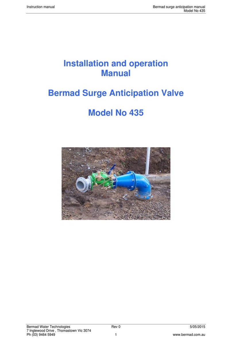
BERMAD 435 User manual

BERMAD
BERMAD FP 430-UF Owner's manual
BERMAD
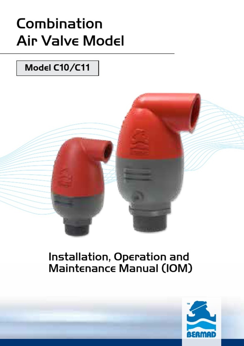
BERMAD C10 User manual

BERMAD
BERMAD 400 Series User manual

BERMAD
BERMAD 430-Z-3W Owner's manual
BERMAD
BERMAD C30 User manual
BERMAD
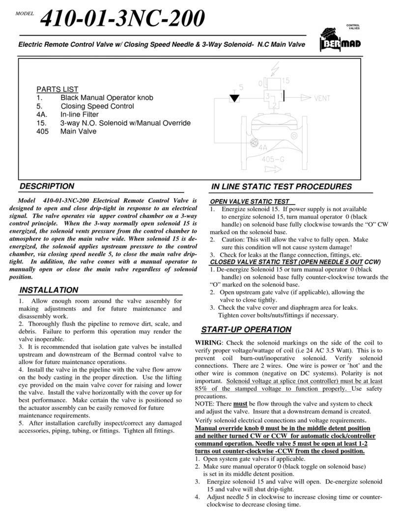
BERMAD 410-01-3NC-200 User manual

BERMAD
BERMAD 450-60 User manual

BERMAD
BERMAD 430 User manual
