b.
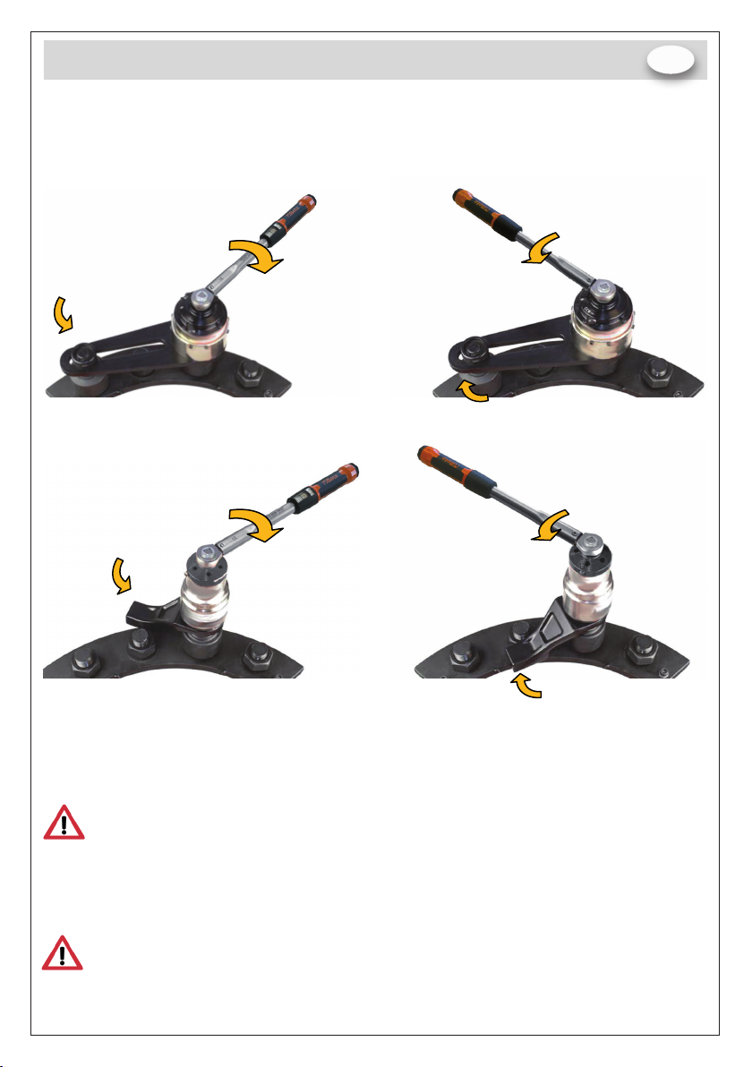
Con la chiave ancora carica, sposta il ‘selet -
tore di direzione del dispositivo antiritorno’ in
direzione antioraria.
FIGURA 5
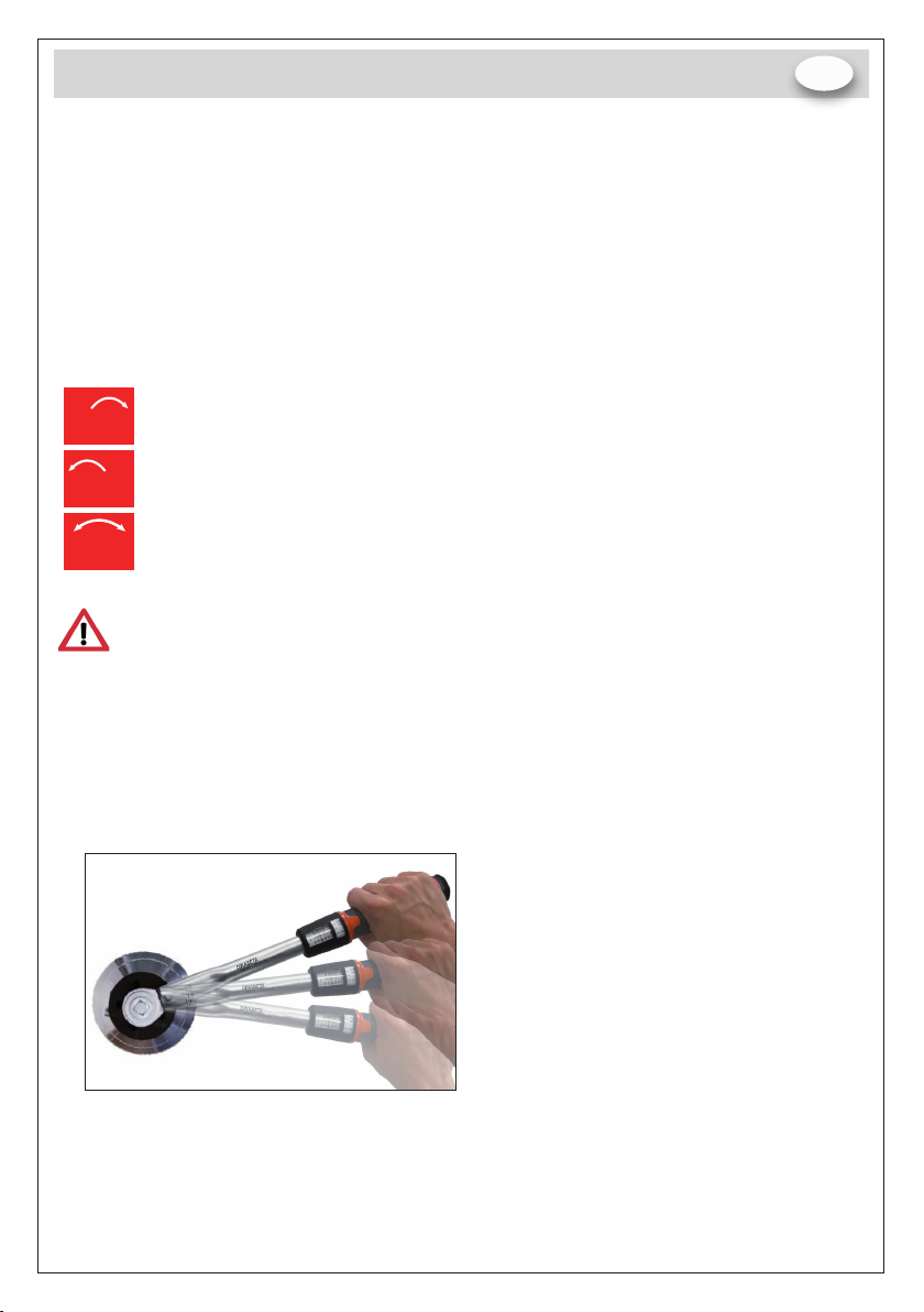
c.
Permettere alla chiave dinamometrica di
ruotare lentamente no a quando il moltipli-
catore diventa libero.
FIGURA 6
Se l’antiritorno non può essere rilasciato, riavviare il dispositivo spingendo il selettore in
direzione antioraria. Riposizionare la chiave e seguire la procedure 3 no a quando il mec-
canismo di antiritorno viene completamente rilasciato.Testare la direzione di rotazione e
assicurarsi che il dispositivo operi liberamente.
4. L’utensile può essere rimosso dal dispositivo di ssaggio.
5. Familiarizzare con questo articolo applicando, inizialmente, basse coppie e il dispositivo
di antiritorno.
NOTA: raccomandiamo che gli ingranaggi e i denti del dispositivo antiritorno vengano
sottoposti a un controllo annuale per l’accertamento di usura o danni.
MANUTENZIONE
L’unica manutenzione richiesta all’utente sui moltiplicatori è la sostituzione degli attacchi qua-
dri in uscita. Per evitare danni interni (dovuti soprattutto al sovraccarico della coppia), l’attac-
co quadro in uscita e l’albero sono stati progettati per deformarsi per primi. In questo modo si
evitano danni interni ed è possibile effettuare una facile rimozione.
In alcuni casi l’attacco quadro in uscita non sarà rimovibile senza smontare il coperchio ingra-
naggi. Si consiglia dunque di portare il moltiplicatore ad un rivenditore autorizzato Beta che
provvederà ad inviarlo presso la nostra sede dove avverrà la riparazione.
In molti casi l’ attacco quadro può essere sostituito senza smontare il coperchio ingranag-
gi. Quando si verica questa condizione, rimuovere il bullone che tiene l’attacco quadro in
posizione (il bullone sarà M4 o M5). Quindi rimuovere l’attacco quadro rotto o danneggiato
e montare il nuovo attacco quadro. Stringere il bullone (4,7 Nm per i bulloni M4 e 9 Nm per i
bulloni M5).
Si consiglia di tenere lo strumento in condizioni pulite. Non usare abrasivi o detergenti
a base di solventi.
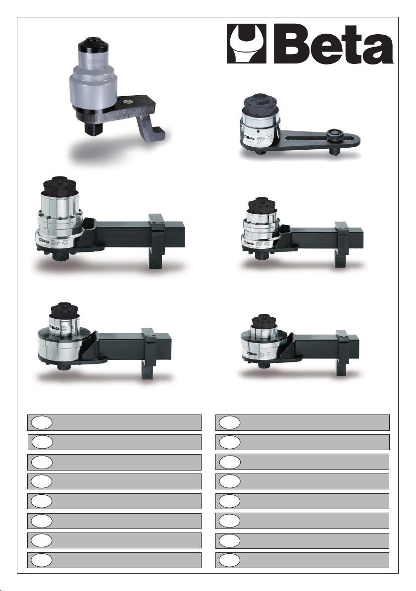
MOLTIPLICATORI DI COPPIA con dispositivo antiritorno
6
IT