BFT ELI-250 User manual

D811232 Ver. 07 20-03-06
IAUTOMAZIONE ELETTROMECCANICA INTERRATA PER CANCELLI A BATTENTE
ELECTROMECHANIC AUTOMATIONS FOR SWING GATES
AUTOMATISME ELECTROMECANIQUE ENTERRÉ POUR PORTAILS A VANTAUX
ELEKTROMECHANISCHER ANTRIEB FÜR FLÜGELGITTERTORE
AUTOMATISMO ELECTROMECANICO SOTERRADO PARA CANCELAS BATIENTES
AUTOMATIZAÇÃO ELECTROMECNICA SUBTERRNEA PARA PORTÕES COM BATENTE
ELI-250
GB
F
D
E
P
ISTRUZIONI D'USO E DI INSTALLAZIONE
INSTALLATION AND USER'S MANUAL
INSTRUCTIONS D'UTILISATION ET D'INSTALLATION
INSTALLATIONS UND GEBRAUCHSANLEITUNG
INSTRUCCIONES DE USO Y DE INSTALACION
INSTRUÇÕES DE USO E DE INSTALAÇÃO
Via Lago di Vico, 44
36015 Schio (VI)
Tel.naz. 0445 696511
Tel.int. +39 0445 696533
Fax 0445 696522
Internet: www.bft.it
E-mail: [email protected]

2 - ELI-250 - Ver. 07
D811232_07

MANUALE D’USO ITALIANO
Nel ringraziarVi per la preferenza accordata a questo prodotto, la ditta è certa che da esso otterrete le prestazioni necessarie al Vostro uso.
Leggete attentamente l’opuscolo ”Avvertenze” ed il ”Libretto istruzioni” che accompagnano questo prodotto, in quanto forniscono importanti
indicazioni riguardanti la sicurezza, l’installazione, l’uso e la manutenzione. Questo prodotto risponde alle norme riconosciute della tecnica e delle
disposizioni relative alla sicurezza. Confermiamo che è conforme alle seguenti Direttive Europee: 89/336/CEE, 73/23/CEE, 98/37/CEE, 99/05/CEE (e
loro modifiche successive). AVVERTENZE! Qualunque intervento sui componenti dell’automazione deve essere eseguito da personale qualificato
(installatore).
1) GENERALITÀ
L’attuatore elettromeccanico ELI-250 è la soluzione ideale per applicazioni interrate sottocardine. L’attuatore è realizzato con un unico riduttore monoblocco
a tenuta stagna. La posizione sottocardine mantiene l’estetica del cancello intatta e rende l’automazione praticamente invisibile. Una volta installata la cassa
portante, il cancello è operativo anche senza montare l’attuatore che può essere inserito successivamente. In caso di manutenzione, questo tipo di cassa
consente di togliere l’attuatore senza smontare l’anta del cancello. L’attuatore ELI-250 è applicabile a qualsiasi tipo di cancello a battente rispondente ai
valori riportati nella tabella dei Dati tecnici. La forza di spinta si regola sulla centralina (vedi manuale specifico). Il funzionamento a fine corsa è regolato
da fermi meccanici situati all’interno della cassa di fondazione.
ATTENZIONE! L’attuatore mod. ELI-250 non è dotato di regolazione meccanica di coppia. É obbligatorio utilizzare un quadro di comando del
medesimo costruttore, conforme ai requisiti essenziali di sicurezza delle direttive 89/336/CEE, 73/23/CEE, 98/37/CEE, 99/05/CEE e dotato di
adeguata regolazione elettrica della coppia.
2) MANOVRA DI EMERGENZA
Lo sblocco di emergenza si effettua agendo, con l’apposita chiave in dotazione, sul gruppetto sblocco situato sotto il cancello sulla parte sporgente della
leva-perno. Per sbloccare, inserire la chiave nel triangolo di sblocco e ruotare la chiave verso l’indicazione del lucchetto aperto per circa 90° (fig.1).
Se l’anta è dotata di elettroserratura, sbloccare anche l’elettroserratura. Spingere manualmente l’anta per aprire/chiudere il cancello. Per ripristinare
l’operazione motorizzata, riposizionare il cancello allineato con la leva che porta il gruppo blocco e girare la chiave verso l’indicazione del lucchet-
to chiuso (fig.1) avendo cura di controllare l’avvenuto aggancio dell’anta. Riporre la chiave di sblocco anta (e dell’elettroserratura se presente) in luogo
conosciuto agli utilizzatori.
3) USO DELL’AUTOMAZIONE
Poichè l’automazione può essere comandata a distanza mediante radiocomando o pulsante di Start, e quindi non a vista, è indispensabile controllare
frequentemente la perfetta efficienza di tutti i dispositivi di sicurezza. Per qualsiasi anomalia di funzionamento, intervenire rapidamente avvalendosi di
personale qualificato. Si raccomanda di tenere i bambini a debita distanza dal raggio di azione dell’automazione.
4) DEMOLIZIONE
L’eliminazione dei materiali va fatta rispettando le norme vigenti. Nel caso di demolizione dell’automazione non esistono particolari pericoli o rischi derivanti
dall’automazione stessa. È opportuno in caso di recupero dei materiali, che vengano separati per tipologia (parti elettriche - rame - alluminio - plastica
- ecc.).
5) SMANTELLAMENTO
Nel caso l’automazione venga smontata per essere poi rimontata in altro sito, bisogna:
• Togliere l’alimentazione e scollegare tutto l’impianto elettrico.
• Togliere il motoriduttore dalla base di fissaggio.
• Smontare il quadro di comando se separato e tutti i componenti dell’installazione.
• Nel caso alcuni componenti non possano essere rimossi o risultino danneggiati, provvedere alla loro sostituzione.
6) MALFUNZIONAMENTO: CAUSE E RIMEDI
Per qualsiasi anomalia di funzionamento non risolta, togliere l’alimentazione al sistema e chiedere l’intervento di personale qualificato (installatore).
Nel periodo di fuori servizio, attivare lo sblocco manuale per consentire l’apertura e la chiusura manuale. In questo periodo, per mantenere il blocco in
chiusura, provvedere a mantenerlo chiuso mediante catena e lucchetto.
Fig. 1
2
1
Max. 90°
ELI-250 - Ver. 07 - 3
D811232_07

USER’S MANUAL
ENGLISH
Thank you for buying this product, our company is sure that you will be more than satisfied with the performance of the product. This product is supplied
with a “Warnings” leaflet and an “Instruction manual”. These should both be read carefully as they provide important information about safety, installation,
operation and maintenance. This product complies with recognised technical standards and safety regulations. We declare that this product is in conformity
with the following European Directives: 89/336/EEC, 73/23/EEC, 98/37/EEC, 99/05/EEC (and subsequent amendments). WARNINGS: Any assistance
required on automation components must be carried out by a qualified technician (installer).
1) GENERAL OUTLINE
The ELI-250 electromechanical actuator is the ideal solution for underground hinge-pivot installation. The actuator consists of a perfectly sealed single-block
reduction gear. The under hinge-pivot position maintains the aesthetic appearance of the gate and practically hides the automation system.
Once the bearing case is installed, the gate can be operated even without fitting the actuator which can be inserted later. When maintenance is required,
this type of case allows the actuator to be taken out without removing the gate leaf. The ELI-250 actuator can be fitted to any type of swing gate which
meets the values shown in the ”Technical Specifications” table. The pushing force is set on the control unit (see specific manual). The end-of-stroke
operation is adjusted by mechanical stops located inside the foundation case. CAUTION! The actuator mod. ELI-250 is not provided with mechanical
torque adjustment. It is compulsory to use a control board of the same manufacturer, according to the basic safety requirements of directives
89/336/EEC, 73/23/EEC, 98/37/EEC, 99/05/EEC and provided with adequate electric torque adjustment.
2) EMERGENCY MANOEUVRE
Emergency release is obtained by using the key provided, on the release unit which is located under the gate, on the protruding section of the lever-pivot.
To release, insert the key in the release triangle and turn it by about 90° in the direction shown by the open-padlock symbol (fig.1). If the leaf is equipped
with an electric lock, release the electric lock as well. To open/close the gate, push it manually. To restore motor-driven operation, reposition the gate by ali-
gning it with the lever bearing the lock unit, and turn the key in the direction shown by the closed-padlock symbol (fig.1) checking that engagement is correctly
restored. Keep the leaf release key (and that of the electric lock, if any) in a place which is known to the users.
3) AUTOMATION OPERATION
Since the automation system can be remotely controlled by means of a radio control device or a Start button, and therefore out of sight, all safety devices
must be frequently checked in order to ensure their perfect efficiency. In the event of any anomalous operation, request immediate assistance from qualified
personnel. Children must be kept at a safe distance from the automation operation area.
4) SCRAPPING
Materials must be disposed of in conformity with the current regulations.
In case of scrapping, the automation devices do not entail any particular risks or danger. In case of recovered materials, these should be sorted out by
type (electrical components, copper, aluminium, plastic etc.).
5) DISMANTLING
When the automation system is disassembled to be reassembled on another site, proceed as follows:
• Disconnect the power supply and the entire electrical installation.
• Remove the gearmotor from its fixing base.
• Disassemble the control panel, if separate, and all installation components.
• In the case where some of the components cannot be removed or are
damaged, they must be replaced.
6) MALFUNCTION: CAUSES AND REMEDIES
When any operational malfunction is found, and not resolved, disconnect the mains power supply and request the assistance of a qualified
technician (installer).
When automation is out of order, activate the manual release to allow the opening and closing operations to be carried out manually.
During this period of time, keep the lock in the closed position by means of a chain and padlock.
Fig. 1
2
1
Max. 90°
4 - ELI-250 - Ver. 07
D811232_07

MANUEL D’UTILISATION FRANÇAIS
Nous vous remercions pour avoir choisi ce produit. Nous sommes certains qu’il vous assurera les performances que vous souhaitez.
Lisez attentivement la brochure “Avertissements” et le “Manuel d’instructions” qui accompagnent ce produit, puisqu’ils fournissent d’importantes indications
concernant la sécurité, l’installation, l’utilisation et l’entretien. Ce produit est conforme aux règles reconnues de la technique et aux dispositions de sécurité.
Nous certifions sa conformité avec les directives européennes suivantes:
89/336/CEE, 73/23/CEE, 98/37/CEE, 99/05/CEE
(et modifications successives).
AVERTISSEMENTS: Toute intervention sur les composants de la motorisation doit être effectuée par du personnel qualifié (installateur).
1) GÉNÉRALITÉS
Le vérin électromécanique ELI-250 est la solution idéale pour des applications enterrées sous les gonds. Le vérin est réalisé avec un seul réducteur mo-
nobloc étanche. La caisse de fondation sous les gonds ne compromet pas l’esthétique du portail et rend la motorisation pratiquement invisible.
Après avoir installé la caisse porteuse, le portail peut être actionné même sans monter le vérin. Celuici peut être monté par la suite. En cas d’entretien, ce
type de caisse permet d’enlever le vérin sans avoir à démonter le vantail du portail. Le vérin ELI-250 peut être appliqué sur n’importe quel type de portail
battant conforme aux valeurs indiquées dans le tableau des Caractéristiques techniques. La force de poussée se règle sur la centrale de commande
(voir manuel spécifique). Le fonctionnement à la fin de la course est réglé par des butées mécaniques situées à l’intérieur de la caisse de fondation. AT-
TENTION: L’actionneur mod. ELI-250 n’est pas doté d’un réglage mécanique de couple. Il est obligatoire d’utiliser un tableau de commande du
même constructeur, conformément aux exigences essentielles de sécurité des directives
89/336/CEE, 73/23/CEE, 98/37/CEE, 99/05/CEE
et doté
d’un réglage électrique du couple adéquat.
2) MANOEUVRE D’URGENCE
Le déblocage d’urgence se fait en agissant, avec la clé spéciale fournie en dotation, sur le groupe de déblocage situé sous le portail sur la partie saillante
du levier-pivot. Per effectuer le déblocage, enfoncer la clé dans le triangle de déblocage et tourner la clé vers l’indication du cadenas ouvert pour environ
90° (fig.1). Si le vantail est doté d’électroserrure, débloquer aussi l’électroserrure. Pousser le vantail manuellement pour ouvrir/fermer le portail.
Pour rétablir le fonctionnement motorisé, repositionner le portail aligné avec le levier portant le groupe de blocage et tourner la clé vers l’indication du
cadenas fermé (fig.1) en ayant soin de contrôler si le vantail s’est accroché. Ranger la clé de déblocage du vantail (et de l’életroserrure, si existante) dans
un lieu connu per les utilisateurs.
3) UTILISATION DE LA MOTORISATION
Afin que la motorisation puisse être commandée à distance avec une radiocommande ou un bouton de start, et donc avec le portail non à vue , il faut
contrôler souvent le parfait fonctionnement de tous les dispositifs de sécurité. En cas de défaillances, il faut intervenir rapidement en s’adressant à du
personnel qualifié. Il est recommandé de tenir les enfants loin du rayon d’action de la motorisation.
4) DÉMOLITION
L’élimination des matériaux doit être faite en respectant les normes en vigueur. En cas de démolition de la motorisation, il n’existe aucun danger ou risque
particulier dérivant de la motorisation. En cas de récupération des matériaux, il sera opportun de les trier selon leur genre (parties électriques - cuivre
- aluminium - plastique - etc.).
5) DÉMANTÈLEMENT
Si la motorisation doit être démontée et remontée ailleurs, il faut:
• Couper l’alimentation et débrancher toute l’installation électrique.
• Enlever le motoréducteur de sa base de fixation.
• Démonter l’unité de commande si séparée et tous les composants de l’installation.
• Si des composants ne peuvent pas être enlevés ou sont endommagés, il faudra les remplacer.
6) MAUVAIS FONCTIONNEMENT: CAUSES ET REMÈDES
Pour n’importe quelle anomalie de fonctionnement non résolue, couper l’alimentation au système et s’adresser à du personnel qualifié (installateur).
Pendant la période de hors service, activer le déblocage manuel pour permettre l’ouverture et la fermeture manuelle. Pendant cette période, pour maintenir
le blocage en fermeture, maintenir le portail fermé en utilisant une chaîne et un cadenas.
Fig. 1
2
1
Max. 90°
ELI-250 - Ver. 07 - 5
D811232_07

BEDIENUNGSANLEITUNG
DEUTSCH
Wir danken Ihnen, daß Sie sich für diese Anlage entschieden haben. Ganz sicher wird sie die Leistungen erbringen, die für Ihre Ansprüche erfor-
derlich sind. Lesen Sie aufmerksam die Broschüre “Hinweise” und die “Gebrauchsanweisungen” durch, die dem Produkt beiliegen.
Sie enthalten wichtige Hinweise zur Sicherheit, Installation, Bedienung und Wartung der Anlage. Dieses Produkt genügt den anerkannten technischen
Normen und Sicherheitsbestimmungen. Wir bestätigen, daß es mit folgenden Europäischen Richtlinien übereinstimmt: 89/336/EWG, 73/23/EWG, 98/37/
EWG, 99/05/EWG (und ihren nachfolgende Änderungen). HINWEISE: Jede Art von Arbeit an den Antriebskomponenten ist von Fachpersonal (In-
stallateur) vorzunehmen.
1) ALLGEMEINES
Der elektromechanische Antrieb ELI-250 ist die ideale Lösung für den unterflurigen Einbau unterhalb der Torangel. Der Antrieb ist nämlich aus einem
einzigen hermetisch schließenden Monoblock gefertigt. Der Fundamentkasten sorgt dafür, daß die Optik des Tores nicht beeinträchtigt wird und macht die
Anlage nahezu unsichtbar. Nach der Montage des Grundkastens ist das Tor auch ohne Antrieb, der nachträglich eingebaut werden kann, funktionsfähig.
Diese Art von Kasten ermöglicht es, den Antrieb zu Wartungszwecken auszubauen, ohne den Torflügel abnehmen zu müssen. Das Modell ELI-250 kann an
alle Flügelgittertore angebracht werden, deren Werte mit den technischen Daten in der Tabelle übereinstimmen. Die Schubkraft wird über die Steuerung
geregelt (siehe das entsprechende Handbuch). Der Endanschlagsbetrieb wird durch mechanische Blockierungselemente innerhalb des Fundamentka-
stens gesteuert. ACHTUNG:Der Trieb Modell ELI-250 ist nicht mit mechanischer Drehmoment Einstellung ausgestattet. Es ist obligatorisch, eine
Steuertafel des gleichen Herstellers zu verwenden, die den grundlegenden Sicherheitsanforderungen der Direktiven 89/336/EWG, 73/23/EWG,
98/37/EWG, 99/05/EWG entspricht und mit entsprechender elektrischer Einstellung des Drehmoments ausgestattet ist.
2) BEDIENUNG IM NOTFALL
Die Entsperrung im Notfall erfolgt durch den beiliegenden Schlüssel, der in die Entsperrungsvorrichtung gesteckt wird. Sie befindet sich unter dem Tor auf
dem hervorragenden Bestandteil der Einheit Hebel-Zapfen. Zur Entsperrung ist der Schlüssel in das Entsperrungsdreieck einzusetzen und um ca. 90° in
die Richtung des angezeigten offenen Vorhängeschlosses zu drehen (Abb.1). Sofern der Flügel über ein Elektroschloß verfügt, muß auch das Elektro-
schloß entsperrt werden. Den Flügel von Hand drücken, um das Tor zu öffnen bzw. zu schließen. Um den Motorbetrieb wiederaufzunehmen, ist das Tor auf
einer Linie mit dem Hebel, der die Blockierungsvorrichtung trägt, auszurichten. Drehen Sie den Schlüssel in die Richtung des angezeigten geschlossenen
Vorhängeschlosses (Abb.1). Überprüfen Sie, ob die Einheit wieder richtig eingerastet ist. Bewahren Sie den Schlüssel zur Entsperrung (und des Elektro-
schlosses, falls vorhanden) an einem Ort auf, der allen Benutzern bekannt ist.
3) BEDIENUNG DER ANLAGE
Der Antrieb kann mit Hilfe einer Fernbedienung oder eines Startknopfes auf Distanz und damit ohne Blickkontakt bedient werden. Die häufige Kontrolle aller
Sicherheitsvorrichtungen auf ihre einwandfreie Funktionsfähigkeit ist deshalb unumgänglich. Bei jeder Betriebsstörung greifen Sie rasch ein und ziehen
bei Bedarf Fachleute hinzu. Kinder sind in gebührlichem Abstand zum Aktionsradius der Anlage zu halten.
4) VERSCHROTTUNG
Die Materialien sind unter Beachtung der einschlägigen Vorschriften zu entsorgen. Bei der Verschrottung gehen von der Anlage keine besonderen Ge-
fahren oder Risiken aus. Werden die Materialien wiederverwertet, sollten sie nach Arten getrennt werden (elektrische Komponenten - Kupfer - Aluminium
- Plastik usw).
5) ABBAU
Wird die Anlage abgebaut, um sie an einem anderen Ort erneut zu installieren, ist folgendes zu beachten:
• Stromversorgung unterbrechen und die gesamte elektrische Anlage abklemmen.
• Den Getriebemotor von der Befestigungsunterlage nehmen.
• Die Bedientafel, falls separat, und alle Anlagenbauteile demontieren.
• Teile, die nicht entfernt werden können oder beschädigt sind, müssen ersetzt werden.
6) BETRIEBSSTÖRUNGEN: URSACHEN UND ABHILFEN
Bei jeder nicht behobenen Betriebsstörung die Stromversorgung der Anlage unterbrechen und Fachpersonal anfordern (Monteur). Wenn die Anlage außer
Betrieb ist, muß die Handentsperrung aktiviert werden, damit das Tor von Hand geöffnet und geschlossen werden kann. In dieser Zeit ist das Tor durch
Kette und Vorhängeschloß zu versperren.
Fig. 1
2
1
Max. 90°
6 - ELI-250 - Ver. 07
D811232_07

MANUAL DE USO ESPAÑOL
Al agradecerle la preferencia que ha manifestado por este producto, la empresa está segura de que de él obtendrá las prestaciones necesarias para sus
exigencias. Lea atentamente el folleto “Advertencias” y el “Manual de Instrucciones” que lo acompañan, pues proporcionan importantes indicaciones
referentes a la seguridad, la instalación, el uso y el mantenimiento. Este producto cumple los requisitos establecidos por las normas reconocidas de la
técnica y las disposiciones relativas a la seguridad, y es conforme a las siguientes Directivas Europeas: 89/336/CEE, 73/23/CEE, 98/37/CEE, 99/05/CEE (y
modificaciones sucesivas). ADVERTENCIAS! Cualquier intervención sobre los componentes del automatismo debe ser realizada por personal
cualificado (instalador).
1) GENERALIDADES
El servomotor electromecánico ELI-250 es la solución ideal para aplicaciones soterradas bajo el quicio. El servomotor está realizado con un único reductor
monobloque estanco. La posición bajo el quicio mantiene la estética de la cancela intacta y hace el automatismo prácticamente invisible. Una vez instalada
la caja portante, la cancela es operativa incluso sin montar el servomotor, que se puede insertar sucesivamente. En caso de mantenimiento, este tipo de
caja permite sacar el servomotor sin tener que desmontar la hoja de la cancela. El servomotor ELI-250 puede aplicarse a cualquier tipo de cancela batiente
que respete los valores indicados en la tabla de los Datos técnicos. La fuerza de empuje se regula en la central (véase el manual de instrucciones
específico). El funcionamiento de fin de carrera es regulado mediante retenes mecánicos situados dentro de la caja de cimentación.
ATENCION!El actuador mod. ELI-250 no posee la regulación mecánica del par. Es obligatorio usar un cuadro de mando del mismo fabricante,
conforme a los requisitos de seguridad esenciales de las directivas 89/336/CEE, 73/23/CEE, 98/37/CEE, 99/05/CEE y que esté equipado con la
regulación eléctrica adecuada del par.
2) MANIOBRA DE EMERGENCIA
El desbloqueo de emergencia se efectúa actuando, con la llave expresamente asignada, sobre el grupo de desbloqueo situado debajo de la cancela, en
la parte saliente de la palanca-perno. Para desbloquear, hay que insertar la llave en el triángulo de desbloqueo y girarla hacia la indicación del candado
abierto unos 90° (fig.1). Si la hoja está dotada de electrocerradura, ésta también tiene que desbloquearse. Empujar manualmente la hoja para abrir y cerrar
la cancela. Para restablecer la operación motorizada, hay que volver a alinear la cancela con la palanca de accionamiento del grupo de bloqueo y girar la
llave hacia la indicación del candado cerrado (fig.1), controlando que la hoja se haya enganchado efectivamente. La llave de desbloqueo de la hoja (y de
la electrocerradura, si está presente) debe guardarse en un lugar conocido por los usuarios.
3) USO DEL AUTOMATISMO
Debido a que el automatismo puede accionarse a distancia mediante radiomando o botón de Start y, por tanto, no a la vista, es indispensable controlar
frecuentemente la perfecta eficiencia de todos los dispositivos de seguridad. Ante cualquier anomalía de funcionamiento, hay que intervenir rápidamente
sirviéndose de personal especializado. Se recomienda mantener a los niños fuera del campo de acción del automatismo.
4) DEMOLICIÓN
La eliminación de los materiales debe hacerse respetando las normas vigentes. En el caso de demolición de un automatismo, no existen particulares pe-
ligros o riesgos que deriven del automatismo mismo. Es conveniente, en caso de recuperación de materiales, que se separen por tipos (partes eléctricas,
cobre, aluminio, plástico, etc.).
5) DESMANTELAMIENTO
Caso de que se desmonte el automatismo para después volver a montarlo en otro lugar, es necesario:
• Cortar la alimentación y desconectar toda la instalación eléctrica.
• Quitar el motorreductor de la base de fijación.
• Desmontar el cuadro de control, si está separado, y todos los componentes de la instalación.
• Caso de que algunos componentes no puedan sacarse o resulten dañados, habrá que sustituirlos.
6) MAL FUNCIONAMIENTO: CAUSAS Y SOLUCIONES
Ante cualquier anomalía de funcionamiento no resuelta, hay que cortar el suministro de corriente al sistema y solicitar la intervención de personal cualificado
(instalador). Para el período de fuera de servicio, es necesario activar el dispositivo de desbloqueo manual para permitir la apertura y el cierre manuales.
En este período, para mantener el bloqueo cuando la cancela está cerrada, se utilizará una cadena y un candado.
Fig. 1
2
1
Max. 90°
ELI-250 - Ver. 07 - 7
D811232_07

MANUAL PARA DE USO
PORTUGUÊS
Agradecendolhe pela preferência dada a este produto, a Empresa tem a certeza que do mesmo obterá as prestações necessárias ao seu uso.
Leia atentamente o fascículo ”Advertências” e o ”Manual de instruções” que acompanham este produto, pois que fornecem indicações Importantes
respeitantes a segurança, a instalação, o uso e a manutenção. Este produto responde às normas reconhecidas da técnica e das disposições relativas à
segurança. Confirmamos que está em conformidade com as seguintes directivas europeias: 89/336/CEE, 73/23/CEE, 98/37/CEE, 99/05/EE (e modificações
sucessivas). RECOMENDAÇÕES! Toda e qualquer intervenção nos componentes da automatização deve ser efectuada por pessoal qualificado
(instalador).
1) GENERALIDADES
O atuador electromecânico ELI-250 é a solução ideal para aplicações embutidas sob as dobradiças. O atuador é fabricado com um único redutor monobloco
completamente vedado. A posição sob as dobradiças mantém a estética do portão e torna a automatização praticamente invisível. Uma vez instalada a
caixa portante, o portão está em condições de operação mesmo sem montar o atuador que pode ser inserido sucessivamente.
Em caso de manutenção, este tipo de caixa consente tirar o atuador sem desmontar a folha do portão. O atuador ELI-250 é aplicável a qualquer tipo de
portão de batentes que atenda aos valores indicados na tabela dos Dados técnicos. A força de empuxo é regulada na central de comando (ver manual
específico). O funcionamento em fim de curso é regulado por meio de stops mecânicos situados internamente à caixa de fundação.
ATENÇÃO! O accionador mod. ELI-250 não está dotado de regulação mecânica de binário. É obrigatório utilizar um quadro de comando do
mesmo fabricante, conforme aos requisitos essenciais de segurança das directivas 89/336/CEE, 73/23/CEE, 98/37/CEE, 99/05/EE e dotado de
adequada regulação eléctrica do binário.
2) MANOBRA DE EMERGÊNCIA
Efetua-se o desbloqueio de emergência, atuando com a chave específica em dotação, sobre o conjunto de desbloqueio localizado sob o portão na parte
saliente da alavancaeixo. Para desbloquear, introduzir a chave no triângulo de desbloqueio e girar a mesma em direção da indicação de cadeado aberto
por aproximadamente 90° (fig.1). Se a folha do portão for dotada de fechadura eléctrica, desbloquear também a fechadura eléctrica. Empurrar manualmente
a folha do portão para abrir/fechar o mesmo. Para retornar à operação motorizada, reposicionar o portão alinhado com a alavanca que tem o conjunto
de bloqueio e girar a chave em direção da indicação do cadeado fechado (fig.1) tendo o cuidado de verificar a ocorrência do engate da folha do portão.
Repor a chave de desbloqueio da folha do portão (e da fechadura eléctrica se presente) em local conhecido aos usuários.
3) USO DA AUTOMATIZAÇÃO
Já que a automatização pode ser comandada a distância por meio de um controle remoto ou botão de Start, e conseqüentemente não visualmente, é
indispensável verificar freqüentemente a perfeita eficiência de todos os dispositivos de segurança. Em caso de qualquer anomalia de funcionamento,
intervir rapidamente valendo-se de pessoal qualificado. Recomenda-se manter as crianças a uma distância segura do raio de ação da automatização.
4) DEMOLIÇÃO
A eliminação dos materiais deve ser feita respeitando-se as normas vigentes. Em caso de demolição da automatização não existem perigos particulares
ou riscos derivantes da própria automatização. É oportuno, no caso da recuperação dos materiais, que os mesmos sejam separados por tipologia (partes
eléctricas, cobre, alumínio,plástico, etc.).
5) DESMANTELAMENTO
Caso a automatização seja desmontada para ser remontada em seguida num outro sítio, é necessário:
• Interromper alimentação e desligar todo o sistema eléctrico.
• Desmontar o motoredutor da base de fixação.
• Desmontar o quadro de comando se separado e todos os componentes da instalação.
• Caso alguns componentes não possam ser removidos ou estejam danificados, efectuar a substituição dos mesmos.
6) MAU FUNCIONAMENTO: CAUSAS E SOLUÇÕES
Em caso de qualquer anomalia de funcionamento não solucionada, interromper a alimentação do sistema e solicitar a presença de pessoal qualificado
(instaladores). Durante o período for a de serviço, ativar o desbloqueio manual para consentir a abertura e fechamento manuais. Neste período, para
manter o bloqueio quando fechado, mantêlo trancado por meio de corrente e cadeado.
Fig. 1
2
1
Max. 90°
8 - ELI-250 - Ver. 07
D811232_07

Nel ringraziarVi per la preferenza accordata a questo prodotto, la ditta è certa
che da esso otterrete le prestazioni necessarie al Vostro uso.
Leggete attentamente l’opuscolo ”Avvertenze” ed il ”Libretto istruzioni” che
accompagnano questo prodotto, in quanto forniscono importanti indicazioni
riguardanti la sicurezza, l’installazione, l’uso e la manutenzione.
Questo prodotto risponde alle norme riconosciute della tecnica e delle
disposizioni relative alla sicurezza. Confermiamo che è conforme alle
seguenti Direttive Europee: 89/336/CEE, 73/23/CEE, 98/37/CEE, 99/05/CEE
(e loro modifiche successive).
AVVERTENZE! Qualunque intervento sui componenti dell’automazione
deve essere eseguito da personale qualificato (installatore).
1) GENERALITÀ
L’attuatore elettromeccanico ELI-250 è la soluzione ideale per applicazioni
interrate sottocardine. L’attuatore è realizzato con un unico riduttore mono-
blocco a tenuta stagna. La posizione sottocardine mantiene l’estetica del
cancello intatta e rende l’automazione praticamente invisibile.
Una volta installata la cassa portante, il cancello è operativo anche senza
montare l’attuatore che può essere inserito successivamente.
In caso di manutenzione, questo tipo di cassa consente di togliere l’attua-
tore senza smontare l’anta del cancello. L’attuatore ELI-250 è applicabile a
qualsiasi tipo di cancello a battente rispondente ai valori riportati nella tabella
dei Dati tecnici. La forza di spinta si regola sulla centralina (vedi manuale
specifico). Il funzionamento a fine corsa è regolato da fermi meccanici situati
all’interno della cassa di fondazione.
ATTENZIONE! L’attuatore mod. ELI-250 non è dotato di regolazione
meccanica di coppia. É obbligatorio utilizzare un quadro di comando
del medesimo costruttore, conforme ai requisiti essenziali di sicurezza
delle direttive 89/336/CEE, 73/23/CEE, 98/37/CEE, 99/05/CEE e dotato di
adeguata regolazione elettrica della coppia.
2) SICUREZZA GENERALE
ATTENZIONE! Una installazione errata o un uso improprio del prodot-
to, può creare danni a persone, animali o cose.
•
Leggete attentamente l’opuscolo ”Avvertenze” ed il ”Libretto istruzio-ni”
che accompagnano questo prodotto, in quanto forniscono Importanti indi-
cazioni riguardanti la sicurezza, l’installazione, l’uso e la manutenzione.
• Smaltire i materiali di imballo (plastica, cartone, polistirolo, ecc.) secon-
do quanto previsto dalle norme vigenti. Non lasciare buste di nylon e
polistirolo a portata dei bambini.
• Conservare le istruzioni per allegarle al fascicolo tecnico e per consul-
tazioni future.
• Questo prodotto è stato progettato e costruito esclusivamente per l’utilizzo
indicato in questa documentazione.
Usi non indicati in questa documentazione potrebbero essere fonte di
danni al prodotto e fonte di pericolo.
• La Ditta declina qualsiasi responsabilità derivante dall’uso improprio o
diverso da quello per cui è destinato ed indicato nella presente docu-
mentazione.
• Non installare il prodotto in atmosfera esplosiva.
• Gli elementi costruttivi della macchina devono essere in accordo con le
seguenti Direttive Europee: 89/336/CEE, 73/23/CEE, 98/37/CEE, 99/05/CEE
e loro modifiche successive. Per tutti i Paesi extra CEE, oltre alle norme
nazionali vigenti, per un buon livello di sicurezza è opportuno rispettare
anche le norme sopracitate.
• La Ditta declina qualsiasi responsabilità dall’inosservanza della Buona
Tecnica nella costruzione delle chiusure (porte, cancelli, ecc.), nonché
dalle deformazioni che potrebbero verificarsi durante l’uso.
•
L’installazione deve essere in accordo con quanto previsto dalle Direttive
Europee:
89/336/CEE, 73/23/CEE, 98/37/CEE, 99/05/CEE
e loro modifiche
successive.
• Togliere l’alimentazione elettrica, prima di qualsiasi intervento sull’im-
pianto. Scollegare anche eventuali batterie tampone se presenti.
• Prevedere sulla rete di alimentazione dell’automazione, un interruttore
o un magnetotermico onnipolare con distanza di apertura dei contatti
uguale o superiore a 3,5 mm.
• Verificare che a monte della rete di alimentazione, vi sia un interruttore
differenziale con soglia da 0.03A.
• Verificare se l’impianto di terra è realizzato correttamente: collegare tutte
le parti metalliche della chiusura (porte, cancelli, ecc.) e tutti i componenti
dell’impianto provvisti di morsetto di terra.
• Applicare tutti i dispositivi di sicurezza (fotocellule, coste sensibili, ecc.)
necessari a proteggere l’area da pericoli di schiacciamento, convoglia-
mento, cesoiamento, secondo ed in conformità alle direttive e norme
tecniche applicabili.
• Applicare almeno un dispositivo di segnalazione luminosa (lampeggiante)
in posizione visibile, fissare alla struttura un cartello di Attenzione.
• La Ditta declina ogni responsabilità ai fini della sicurezza e del buon
funzionamento dell’automazione se vengono impiegati componenti di
altri produttori.
• Usare esclusivamente parti originali per qualsiasi manutenzione o ripa-
razione.
• Non eseguire alcuna modifica ai componenti dell’automazione se non
espressamente autorizzata dalla Ditta.
• Istruire l’utilizzatore dell’impianto per quanto riguarda i sistemi di coman-do
applicati e l’esecuzione dell’apertura manuale in caso di emergenza.
• Non permettere a persone e bambini di sostare nell’area d’azione del-
l’automazione.
• Non lasciare radiocomandi o altri dispositivi di comando alla portata dei
bambini onde evitare azionamenti involontari dell’automazione.
• L’utilizzatore deve evitare qualsiasi tentativo di intervento o riparazione
dell’automazione e rivolgersi solo a personale qualificato.
• Tutto quello che non è espressamente previsto in queste istruzioni, non
è permesso.
3) PARTI PRINCIPALI DELL’AUTOMAZIONE
Attuatore meccanico stagno (fig.1) costituito da:
a) Motore monofase 2 poli protetto da disgiuntore termico.
b) Riduttore a doppia vite senza fine con ingranaggio uscita in lega speciale
di alluminio.
c) Leva uscita e fermi meccanici.
d) Cassa di fondazione portante (predispone all’automazione).
e) Serie di leve per la movimentazione del cancello.
f) Gruppo sblocco con chiave.
ATTENZIONE! L’attuatore può essere montato sia destro che sinistro
e per convenzione si osserva il cancello dal lato interno (verso di
apertura).
4) DATI TECNICI
Alimentazione monofase: .......................................230Vac ±10% 50Hz (*)
Giri motore: ...................................................................................1400min-1
Giri albero uscita: ...............................ELI250 0.95min-1 - ELI250V 1.9min-1
Potenza assorbita: .............................................................................. 280W
Condensatore: ..................................................................................... 10µF
Corrente assorbita: ...............................................................................1.4A
Tempo di apertura 120°: .................................... ELI250 28s - ELI250V 14s
Coppia max.: ..........................................ELI250 380Nm - ELI250V 240Nm
Lunghezza/peso max. anta: ...........................ELI250 2.5m/3000N (~ 300kg)
ELI250 3.5m/2500N (~ 250kg)
ELI250V 2m/1500N (~150kg)
Apertura max. anta: ..............................................................................120°
Mantenimento blocco: ................Motoriduttore irreversibile; elettroserratura
obbligatoria per ante superiori a 2.5m di lunghezza
Reazione all’urto: .................. Frizione elettronica (con quadro di comando)
Manovra manuale: ........................................................... Chiave di sblocco
Max. n° manovre 24 ore: ........................................................................ 100
Protezione termica: .......................................................130°C autoripristino
Condizioni ambiente: .......................................................da -20°C a +50°C
Lubrificazione: ..............................................................Grasso permanente
Grado di protezione: .......................................................................IP67 AM
Peso attuatore: .......................................................................100N (~10kg)
Dimensioni ingombro: ....................................................................Vedi fig.3
(*) Tensioni speciali di alimentazione a richiesta.
5) INSTALLAZIONE DELL’ATTUATORE
5.1) Verifiche preliminari
Controllare:
• Che la cerniera superiore sia in buono stato e possibilmente del tipo
regolabile.
• Che sia possibile eseguire lo scavo per l’interramento della cassa sotto
il cardine.
• Che siano installate le battute d’arresto delle ante ”FA” (fig.8).
• Sistemare o sostituire le parti difettose o usurate delle strutture da mo-
vimentare. In fig.1, è riportato un esploso dell’installazione.
L’affidabilità e la sicurezza dell’automazione è direttamente influenzata
dallo stato della struttura del cancello.
5.2) Componenti principali per una automazione sono (Fig.2):
I) Interruttore onnipolare omologato di adeguata portata con apertura contatti
di almeno 3,5 mm provvisto di protezione contro i sovraccarichi ed
MANUALE PER L’INSTALLAZIONE ITALIANO
ELI-250 - Ver. 07 - 9
D811232_07

i corti circuiti, atto a sezionare l’automazione dalla rete. Installare a
monte dell'automazione, se non già presente, un interruttore onnipolare
omologato con soglia 0,03A.
Qr) Quadro comando e ricevente incorporata.
S) Selettore a chiave.
AL) Lampeggiante con antenna accordata.
M) Attuatore.
E) Elettroserratura (obbligatoria per ante superiori a 2.5m di lunghez-
za).
Fte) Coppia fotocellule esterne (parte emittente).
Fre) Coppia fotocellule esterne (parte ricevente).
Fti) Coppia fotocellule interne con colonnine CF (parte emittente).
Fri) Coppia fotocellule interne con colonnine CF (parte ricevente).
T) Trasmittente 1-2-4 canali.
RG58)
Cavo per antenna.
D) Scatola di derivazione.
5.3) Predisposizione impianto elettrico
Predisporre l’impianto elettrico come indicato in fig.2 facendo riferimento
alle norme vigenti per gli impianti elettrici CEI 64-8, IEC364, armonizzazione
HD384 ed altre norme nazionali. Tenere nettamente separati i collegamenti di
alimentazione di rete dai collegamenti di servizio (fotocellule, coste sensibili,
dispositivi di comando ecc.).
ATTENZIONE! Per il collegamento alla rete, utilizzare cavo multipolare
di sezione minima 3x1.5mm2 e del tipo previsto dalle normative vigenti.
A titolo di esempio, se il cavo è all’esterno (all’aperto), deve essere
almeno pari a H07RN-F mentre, se all’interno (in canaletta), deve essere
almeno pari a H05 VV-F con sezione 3x1.5mm2 .
Realizzare i collegamenti dei dispositivi di comando e di sicurezza in armonia
con le norme per l’impiantistica precedentemente citate. In fig.2 è riportato
il numero di collegamenti e la sezione per una lunghezza dei conduttori di
circa 100 metri; per lunghezze superiori, calcolare la sezione per il carico
reale dell’automazione.
Attenzione! Per il cablaggio dell’attuatore e il collegamento degli accessori
riferirsi ai relativi manuali istruzio ne. I quadri di comando e gli accessori
devono essere adatti all’utilizzo e conformi alle normative vigenti.
5.4) Cementazione della cassa di fondazione
Deve essere cementata in posizione sottocardine considerando che l’albero
portante dell’attuatore deve risultare perfettamente allineato all’asse di rota-
zione dell’anta. Se il cancello è del tipo a cerniere fisse, rimuovere il cancello
e togliere la cerniera inferiore. Se l’anta è sufficientemente alta dal suolo
e non si può rimuovere, provvedere al suo sostegno tramite uno spessore
tra suolo ed anta stessa durante la messa in opera. Se il cancello è del
tipo a cerniere regolabili, togliere quella inferiore, allentare la cerniera
superiore e spostare lateralmente l’anta. Se il cancello è di nuova realiz-
zazione, prevedere una cerniera superiore del tipo regolabile. Eseguire uno
scavo di fondazione delle dimensioni indicate in fig.4. Prevedere un tubo di
scarico (fig.4) per l’acqua piovana in modo da evitare ristagni all’interno della
cassa di fondazione. Predisporre la canaletta per il cavo di alimentazione
fino alla vicina scatola di derivazione ”D”. Realizzare sul fondo, una solida
fondazione (fig.3) dove annegare il cassone di fondazione. Per ottenere una
buona ortogonalità tra casse e ante, traguardare l’allineamento delle stesse
con una corda tesa tra i 2 perni portanti, allineando i 2 riferimenti ”C” tra di
loro (vedi fig.12). Lasciare rapprendere il cemento per il tempo necessario.
6) MONTAGGIO DELL’ANTA
• Ingrassare abbondantemente il perno presente nella cassa di fondazione.
• Posizionare l’assieme leve infilando il tubo A nel perno della cassa di
fondazione come in fig. 9. Nel caso l’altezza delle leve assiemate non sia
sufficiente, prevedere uno spessore ”S” da interporre tra il gruppo leve
assiemate e l’anta del cancello come in fig.5.
• Posizionare le ante in chiusura ed in battuta nel fermo d’arresto centrale.
• Allineare perfettamente il gruppo leve assiemate al cardine.
• Se si usa uno spessore, saldarlo prima all’anta e poi saldare il gruppo
leve allo spessore.
• Verificare il funzionamento dell’anta.
• Se non si inserisce il motoriduttore, montare il coperchio della cassa di
fondazione e fissarlo con le apposite viti.
A questo punto il cancello si apre e si chiude manualmente.
Rimane da posizionare il motoriduttore.
7) MONTAGGIO MOTORIDUTTORE
Togliere i dadi dal fondo della cassa con chiave a tubo CH19.
Il motoriduttore si fissa alla cassa di fondazione nella posizione indicata in
fig.6 e 8, utilizzando i 4 dadi precedentemente tolti.
• Avvitare le viti ”VR” (fig.7) e rispettivi controdadi alle staffe finecorsa ed
individuare la posizione di fissaggio destra o sinistra (fig.8).
• Fissare le staffe dei finecorsa meccanici utilizzando le viti M8 in dota-
zione (fig.7).
• Montare i particolari della leva di collegamento motore-perno, nella
sequenza corretta indicata in fig.9.
Nel caso, la posizione assunta dalle leve, intralci il montaggio dei parti-
colari, dare alimentazione ai motori (tramite la centralina) fino a quando
le leve raggiungono la posizione desiderata.
• Ingrassare il mozzo dentro il quale andrà infilato il tubo A.
• Verificare l’operazione di apertura e chiusura.
• Applicare all’anta le etichette di sblocco interne ed esterne, nel verso e
nella posizione indicata in fig.14. Il simbolo del lucchetto aperto, deve
essere sempre rivolto verso l’asse di rotazione dell’anta.
• E’ necessario fare la connessione del cavo del motoriduttore in una scatola
di derivazione posta all'esterno della cassa di fondazione senza tagliare
il cavo fornito in dotazione (Fig.2-4-5 Rif.D).
8) REGOLAZIONE FINECORSA
Nel caso non ci siano i fermi d’arresto al suolo ”FA”, regolare i fermi d’arresto
interni agendo sulle viti ”VRC-VRO” (fig.10-11) fino a quando l’anta si arresta
nel punto desiderato. La battuta d’arresto meccanica in chiusura e apertura,
si regola agendo nelle apposite viti ”VRC-VRO”.
• In CHIUSURA (fig.10). La vite regolazione finecorsa ”VRC”, deve inter-
cettare la leva ”L” dopo che l’anta è arrivata in battuta nel fermo d’arresto
centrale ”FA” (fig.8). In questo modo è garantito l’appoggio dell’anta al
fermo d’arresto centrale ”FA” che, se fornito di tappo in gomma, evita an-
che i rumori di sbattimento. Qualora nella regolazione del fermo finecorsa
”VRC” la misura ”Z” (fig.8) risultasse maggiore di 18÷20mm, si consiglia
di girare il fermo come in fig.13a.
• In APERTURA (fig.11). La vite regolazione finecorsa ”VRO”, deve inter-
cettare la leva ”L” dopo che l’anta è arrivata in battuta nel fermo d’arresto
di apertura ”FA” (fig.8).
• Ultimata la regolazione, bloccare il controdado delle viti di regolazione finecorsa
”VRO” e la vite che blocca il grano di regolazione finecorsa ”VRC”.
• Ripetere le stesse operazioni anche per il secondo attuatore.
• Se la cassa di fondazione non fosse ortogonale all'anta è possibile
effettuare una compensazione di 10° sia in senso orario che in senso
antiorario, posizionando la staffa di supporto ed il fermo di arresto come
indicato in fig 13b.
9) REGOLAZIONE DELLA COPPIA MOTORE
ATTENZIONE! Se viene utilizzata la centralina mod. ARIES con la coppia
regolata in ”F4” (massima coppia), sono obbligatori i fermi d’arresto al suolo
”FA” sia in apertura che in chiusura. La regolazione di coppia del motore
(antischiacciamento), viene regolata nella centralina di comando. Lo schema
di collegamento del motore è riportata nelle istruzioni d’uso della relativa
centralina di comando. Vedere il manuale istruzione della centralina di co-
mando. La regolazione deve essere tarata per la minima forza necessaria
ad effettuare la corsa di apertura e chiusura completa e comunque entro i
limiti previsti dalle norme vigenti.
ATTENZIONE: Verificare che il valore della forza d’impatto misu-
rato nei punti previsti dalla norma EN12445, sia inferiore a quanto
indicato nella norma EN 12453.
ATTENZIONE! Una regolazione di coppia eccessiva, può compromettere
la sicurezza antischiacciamento. Al contrario, una regolazione di coppia
insufficiente, può non garantire una corsa di apertura o chiusura corretta.
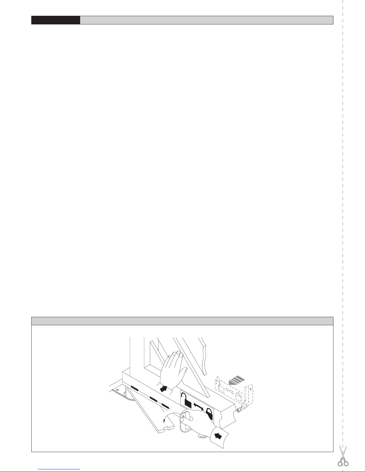
10) MANOVRA DI EMERGENZA
Lo sblocco di emergenza si effettua agendo, con l’apposita chiave in dota-
zione, sul gruppetto sblocco situato sotto il cancello sulla parte sporgente
della leva-perno. Per sbloccare, inserire la chiave nel triangolo di sblocco e
ruotare la chiave verso l’indicazione del lucchetto aperto per circa 90° (fig.14).
Se l’anta è dotata di elettroserratura, sbloccare anche l’elettroserratura.
Spingere manualmente l’anta per aprire/chiudere il cancello. Per ripristinare
l’operazione motorizzata, riposizionare il cancello allineato con la leva che
porta il gruppo blocco e girare la chiave verso l’indicazione del lucchetto
chiuso (fig.14) avendo cura di controllare l’avvenuto aggancio dell’anta. Ri-
porre la chiave di sblocco anta (e dell’elettroserratura se presente) in luogo
conosciuto agli utilizzatori.
11) VERIFICA DELL’AUTOMAZIONE
Prima di rendere definitivamente operativa l’automazione, controllare scru-
polosamente quanto segue:
MANUALE PER L’INSTALLAZIONE
ITALIANO
10 - ELI-250 - Ver. 07
D811232_07

MANUALE PER L’INSTALLAZIONE ITALIANO
• Verificare che tutti i componenti siano fissati saldamente.
• Controllare il corretto funzionamento di tutti i dispositivi di sicurezza
(fotocellule, coste sensibili, ecc.).
• Verificare il comando della manovra di emergenza.
• Verificare l’operazione di apertura e chiusura con i dispositivi di co-
mando applicati.
• Verificare la logica elettronica di funzionamento normale o personalizzata.
12) USO DELL’AUTOMAZIONE
Poichè l’automazione può essere comandata a distanza mediante radioco-
mando o pulsante di Start, e quindi non a vista, è indispensabile controllare
frequentemente la perfetta efficienza di tutti i dispositivi di sicurezza. Per
qualsiasi anomalia di funzionamento, intervenire rapidamente avvalendosi
di personale qualificato. Si raccomanda di tenere i bambini a debita distanza
dal raggio di azione dell’automazione.
13) COMANDO
L’utilizzo dell’automazione consente l’apertura e la chiusura del cancello
in modo motorizzato. Il comando può essere di diverso tipo (manuale, con
radiocomando, controllo accessi con tessera magnetica, ecc.) secondo le
necessità e le caratteristiche dell’installazione. Per i vari sistemi di comando,
vedere le relative istruzioni. Gli utilizzatori dell’automazione devono essere
istruiti al comando e all’uso.
14) MANUTENZIONE
Per qualsiasi manutenzione, togliere l’alimentazione al sistema.
• Verificare periodicamente il buono stato dei cardini ed il loro ingrassaggio.
• Dopo 80000 manovre e comunque dopo 5 anni di vita, sostituire la ralla
B (fig.9) avendo cura di pulire accuratamente la zona e sostituire il grasso
vecchio con dell’altro nuovo.
• Eseguire saltuariamente la pulizia delle ottiche della fotocellula.
• Far controllare da personale qualificato (installatore) la corretta regolazione
della frizione elettrica.
• Se il cavo di alimentazione é danneggiato esso deve essere sostituito dal
costruttore o dal suo servizio assistenza tecnica o comunque da persona
con qualifica similare, in modo da prevenire ogni rischio.
• Per qualsiasi anomalia di funzionamento non risolta, togliere alimentazione
al sistema e richiedere l’intervento a personale qualificato (installatore).
Nel periodo di fuori servizio, attivare lo sblocco manuale per consentire
l’apertura e la chiusura manuale.
15) RUMOROSITÀ
Il rumore aereo prodotto dal motoriduttore in condizioni normali di utilizzo è
costante e non supera i 70dB(A).
16) DEMOLIZIONE
L’eliminazione dei materiali va fatta rispettando le norme vigenti. Nel caso
di demolizione dell’automazione non esistono particolari pericoli o rischi
derivanti dall’automazione stessa. È opportuno in caso di recupero dei ma-
teriali, che vengano separati per tipologia (parti elettriche - rame - alluminio
- plastica - ecc.).
17) SMANTELLAMENTO
Nel caso l’automazione venga smontata per essere poi rimontata in
altro sito, bisogna:
• Togliere l’alimentazione e scollegare tutto l’impianto elettrico.
• Togliere il motoriduttore dalla base di fissaggio.
• Smontare il quadro di comando se separato e tutti i componenti del-
l’installazione.
• Nel caso alcuni componenti non possano essere rimossi o risultino
danneggiati, provvedere alla loro sostituzione.
18) MALFUNZIONAMENTO: CAUSE E RIMEDI
Per qualsiasi anomalia di funzionamento non risolta, togliere l’alimentazione
al sistema e chiedere l’intervento di personale qualificato (installatore).
Nel periodo di fuori servizio, attivare lo sblocco manuale per consentire
l’apertura e la chiusura manuale. In questo periodo, per mantenere il blocco
in chiusura, provvedere a mantenerlo chiuso mediante catena e lucchetto.
18.1) Il cancello non apre. Il motore non gira
a) Verificare che fotocellule o coste sensibili non siano sporche o impregnate,
o non allineate. Procedere di conseguenza.
b) Verificare che l’apparecchiatura elettronica sia regolarmente alimentata.
Verificare l’integrità dei fusibili.
c) Verificare il corretto funzionamento dei singoli dispositivi.
d) Se la centralina non funziona, sostituirla.
Nel caso le condizioni sopraelencate diano esito negativo, contattare un
centro assistenza autorizzato.
Se il cavo di alimentazione è danneggiato esso deve essere sostituito
dal costruttore o dal suo servizio assistenza tecnica o comunque da una
persona con qualifica similare, in modo da prevenire ogni rischio.
18.2) Il cancello non apre. L’attuatore vibra ma non avviene il movi-
mento
a) Controllare che il condensatore sia collegato ai morsetti di marcia
del motore.
b) Controllare che il comune del motore (filo celeste) sia collegato cor-
rettamente.
c) Togliere e ridare l’alimentazione al sistema. Il primo comando di start
deve aprire. Nel caso l’attuatore vada in chiusura, invertire i rispettivi
collegamenti di marcia dell’attuatore.
d) Aiutare manualmente l’apertura dell’anta. Se l’anta apre, controllare se
ci sono problemi meccanici all’anta.
Nel caso le condizioni sopra elencate diano esito negativo, aumentare
la coppia nella centralina di comando ed eventualmente contattare un
centro assistenza autorizzato.
AVVERTENZE! Il buon funzionamento dell’attuatore è garantito solo
se vengono rispettati i dati riportati in questo manuale.
La ditta non risponde dei danni causati dall’inosservanza delle norme
di installazione e delle indicazioni riportate in questo manuale.
Le descrizioni e le illustrazioni del presente manuale non sono impe-
gnative. Lasciando inalterate le caratteristiche essenziali del prodotto,
la Ditta si riserva di apportare in qualunque momento le modifiche che
essa ritiene convenienti per migliorare tecnicamente - costruttivamente
e commercialmente il prodotto, senza impegnarsi ad aggiornare la
presente pubblicazione.
ELI-250 - Ver. 07 - 11
D811232_07

Thank you for buying this product, our company is sure that you will be more
than satisfied with the performance of the product. This product is supplied
with a “Warnings” leaflet and an “Instruction manual”. These should both
be read carefully as they provide important information about safety, instal-
lation, operation and maintenance. This product complies with recognised
technical standards and safety regulations. We declare that this product is in
conformity with the following European Directives: 89/336/EEC, 73/23/EEC,
98/37/EEC, 99/05/EEC (and subsequent amendments).
WARNINGS: Any assistance required on automation components must
be carried out by a qualified technician (installer).
1) GENERAL OUTLINE
The ELI-250 electromechanical actuator is the ideal solution for underground
hinge-pivot installation. The actuator consists of a perfectly sealed single-
block reduction gear. The under hinge-pivot position maintains the aesthetic
appearance of the gate and practically hides the automation system.
Once the bearing case is installed, the gate can be operated even without
fitting the actuator which can be inserted later. When maintenance is requi-
red, this type of case allows the actuator to be taken out without removing
the gate leaf. The ELI-250 actuator can be fitted to any type of swing gate
which meets the values shown in the ”Technical Specifications” table. The
pushing force is set on the control unit (see specific manual).
The end-of-stroke operation is adjusted by mechanical stops located inside
the foundation case.
CAUTION! The actuator mod. ELI-250 is not provided with mechanical
torque adjustment. It is compulsory to use a control board of the same
manufacturer, according to the basic safety requirements of directives
89/336/EEC, 73/23/EEC, 98/37/EEC, 99/05/EEC and provided with adequate
electric torque adjustment.
2) GENERAL SAFETY
WARNING! An incorrect installation or improper use of the product
can cause damage to persons, animals or things.
• The “Warnings” leaflet and “Instruction booklet” supplied with this
product should be read carefully as they provide important information
about safety, installation, use and maintenance.
• Scrap packing materials (plastic, cardboard, polystyrene etc) according
to the provisions set out by current standards. Keep nylon or polystyrene
bags out of children’s reach.
• Keep the instructions together with the technical brochure for future
reference.
• This product was exclusively designed and manufactured for the use
specified in the present documentation. Any other use not specified in
this documentation could damage the product and be dangerous.
• The Company declines all responsibility for any consequences resulting
from improper use of the product, or use which is different from that
expected and specified in the present documentation.
• Do not install the product in explosive atmosphere.
• The construction components of this product must comply with the following
European Directives: 89/336/EEC, 73/23/EEC, 98/37/EEC, 99/05/EEC
and subsequent amendments. As for all non-EEC countries, the above-
mentioned standards as well as the current national standards should
be respected in order to achieve a good safety level.
• The Company declines all responsibility for any consequences resulting
from failure to observe Good Technical Practice when constructing closing
structures (door, gates etc.), as well as from any deformation which might
occur during use.
• The installation must comply with the provisions set out by the following
European Directives: 89/336/EEC, 73/23/EEC, 98/37/EEC, 99/05/EEC
and subsequent amendments.
• Disconnect the electrical power supply before carrying out any work on
the installation. Also disconnect any buffer batteries, if fitted.
• Fit an omnipolar or magnetothermal switch on the mains power supply,
having a contact opening distance equal to or greater than 3,5 mm.
• Check that a differential switch with a 0.03A threshold is fitted just before
the power supply mains.
• Check that earthing is carried out correctly: connect all metal parts for
closure (doors, gates etc.) and all system components provided with an
earth terminal.
• Fit all the safety devices (photocells, electric edges etc.) which are needed
to protect the area from any danger caused by squashing, conveying and
shearing, according to and in compliance with the applicable directives
and technical standards.
• Position at least one luminous signal indication device (blinker) where it
can be easily seen, and fix a Warning sign to the structure.
• The Company declines all responsibility with respect to the automation
safety and correct operation when other manufacturers’ components are
used.
• Only use original parts for any maintenance or repair operation.
• Do not modify the automation components, unless explicitly authorised
by the company.
• Instruct the product user about the control systems provided and the
manual opening operation in case of emergency.
• Do not allow persons or children to remain in the automation ope-
ration area.
• Keep radio control or other control devices out of children’s reach, in
order to avoid unintentional automation activation.
• The user must avoid any attempt to carry out work or repair on the automa-
tion system, and always request the assistance of qualified personnel.
• Anything which is not expressly provided for in the present instructions,
is not allowed.
3) MAIN AUTOMATION PARTS
Sealed mechanical actuator (fig.1) including:
a) Single-phase 2-pole motor protected by thermal circuit-breaker.
b) Double worm-screw reduction gear with output gear in special alu-
minium alloy.
c) Output lever and mechanical stops.
d) Bearing foundation case (ready for automation).
e) Series of levers for gate movement.
f) Release unit with key.
CAUTION! The actuator can be fitted either on the left or on the right,
which are conventionally defined by looking at the gate from the inside
(opening direction).
4) TECHNICAL SPECIFICATIONS
Single-phase power supply ..................................... 230Vac ±10% 50Hz (*)
Motor revolutions ..........................................................................1400min-1
Output shaft revolutions ..................... ELI250 0.95min-1 - ELI250V 1.9min-1
Absorbed power ................................................................................. 280W
Capacitor ............................................................................................. 10µF
Absorbed current .................................................................................. 1,4A
Opening time 120° ............................................. ELI250 28s - ELI250V 14s
Max torque ..............................................ELI250 380Nm - ELI250V 240Nm
Max leaf length/weight .............................. ELI250 2.5m/3000N (~300kg)
ELI250 3.5m/2500N (~250kg)
ELI250V 2m/1500n (~150kg)
Max. leaf opening .................................................................................120°
Blocking function ..................................Irreversible gearmotor; electric lock
necessary for leaves longer than 2,5m
Impact reaction ...................................Electronic clutch (with control panel)
Manual manoeuvre ...................................................................Release key
Max. no. manoeuvres in 24 hours .......................................................... 100
Thermal protection .......................................................130°C self-resetting
Environmental conditions ............................................from -20°C to +50°C
Lubrication ......................................................................Permanent grease
Degree of protection .......................................................................IP67 AM
Actuator weight ......................................................................100N (~ 10kg)
Overall dimensions ........................................................................ See fig.3
(*) Special voltages on request.
5) ACTUATOR INSTALLATION
5.1) Preliminary checks
Check that:
• The upper hinge is in good condition and possibly adjustable.
• A hole can be dug for burying the case under the hinge.
• The ”FA” stop plates of the leaves are installed (fig.8).
• Repair or replace the faulty or worn parts of the structures to be subjected
to movement.
An exploded view of the installation is shown in fig.1.
The automation reliability and safety are directly influenced by the
state of the gate structure.
5.2) The main automation components are (Fig.2):
I) Type-approved adequately rated omnipolar circuit breaker with at least
3,5 mm contact opening, provided with protection against overloads
and short circuits, suitable for cutting out automation from the mains.
Place, if not al ready installed, a type-approved differential switch with
a 0.03A threshold just before the automation system.
Qr) Control panel and built-in receiver.
INSTALLATION MANUAL
ENGLISH
12 - ELI-250 - Ver. 07
D811232_07

S) Key selector.
AL) Blinker with tuned antenna.
M) Actuator.
E) Electric lock (compulsory for leaves longer than 2,5m).
Fte) Pair of external photocells (transmitter section).
Fre) Pair of external photocells (receiver section).
Fti) Pair of internal photocells with CF posts (transmitter section).
Fri) Pair of internal photocells with CF posts (receiver section).
T) 1-2-4 channel transmitter.
RG58)
Cable for antenna.
D) Connector block.
5.3) Electrical installation set-up
Lay out the electrical installation as shown in fig. 2, with reference to the CEI
64-8 and IEC 364 provisions, complying with the HD 384 and other national
standards in force for electrical installation. The mains power supply connec-
tions must be kept totally separate from the service connections (photocells,
electric edges, control devices etc.).
WARNING! For connection to the mains, use a multipolar cable with a
minimum of 3x1.5mm2 cross section and complying with the previou-
sly mentioned regulations. For example, if the cable is out side (in the
open), it has to be at least equal to H07RN-F, but if it is on the inside
(or outside but placed in a plastic cable cannel) it has to be or at least
egual to H05VV-F with section 3x1.5mm2.
Connect the control and safety devices in compliance with the previously
mentioned electrical installation standards. Fig. 2 shows the number of con-
nections and the cross section for cables having a length of approximately
100 metres; in case of longer cables, calculate the cross section for the
actual automation load.
Warning! For actuator wiring and accessory connection, refer to the relevant
instruction manuals. The control panels and accessories must be suitable
for use and conform to current standards.
5.4) Foundation case cementing
The foundation case must be cemented under the hinge pivot, taking into
consideration that the actuator bearing shaft must be perfectly aligned with
the leaf rotation axis. If the gate has fixed hinges, remove the gate and the
lower hinge. If the leaf is sufficiently separated from the ground and cannot
be removed, proceed to supporting it by means of a shim placed between
the ground and the leaf during installation. If the gate has adjustable hinges,
remove the lower one, slacken the upper hinge and move the leaf to the
side. If the gate has been recently installed, fit an upper adjustable hinge.
Dig a foundation hole having the dimensions specified in fig.4. Lay an drain
pipe (fig. 4) for rainwater in order to prevent it from being collected inside the
foundation case. Lay a raceway for the power supply cable as far as con-
nector block “D”. Lay a solid foundation (fig.3) at the bottom, where to bury
the foundation box. To obtain good squareness between cases and leaves,
set out their alignment using a stretched rope between the 2 bearing pivots,
and aligning the 2 reference points “C” with each other (see fig.12).
Let the cement harden for the time needed.
6) GATE LEAF FITTING
• Abundantly grease the pivot in the foundation case.
• Position the lever assembly by inserting pipe “A” into the pivot of the
foundation case, as in fig.9. If the height of the assembled levers is not
sufficient, insert shim “S” between the assembled lever unit and the gate
leaf, as in fig.5.
• Place the gate leaves in the closing and in the closed position against the
centre stop plate.
• Perfectly align the assembled lever unit to the hinge.
• If a shim is used, weld it to the leaf first and then weld the lever unit
to the shim.
• Check the leaf operation.
• If the gearmotor is not to be installed, fit the foundation case cover and
fix with suitable screws.
At this stage, the gate opens and closes manually. All that remains to be
done is to position the gearmotor.
7) GEARMOTOR FITTING
Remove the nuts from the bottom of the case using a CH19 socket wrench.
The gearmotor is to be fixed to the foundation case in the position shown in
fig.6 and 8, using the 4 nuts which were previously removed.
• Tighten screws ”VR” (fig.7) and respective locknuts to the end-of-stroke
brackets and identify the left or right fastening position (fig.8).
• Fix the mechanical end-of-stroke brackets using the M8 screws pro-
vided (fig.7).
• Fit the motor-pivot connecting lever components following the correct
sequence given in fig.9.
In the case where the position of the levers interferes with the assembly of
the components, supply the motors with current (by means of the control
unit) until the levers reach the required position.
• Grease the hub where pipe “A” must be inserted.
• Check the opening and closing operations.
• Attach to the leaf the internal and external release labels observing the
direction and position indicated in fig.14. The open-padlock symbol must
always be directed towards the leaf rotation axis.
• Connection of the gearmotor cable must be carried out in a junction box
positioned outside the foundation case without cutting the cable supplied
as standard (Fig.2-4-5 Ref.D).
8) END-OF-STROKE ADJUSTMENT
If no ground stop plates “FA” are fitted, adjust the internal stops using the
screws “VRC-VRO” (fig.10-11) until the leaf stops at the required point.
The mechanical stop for the opening and closing operations can be adjusted
by means of the appropriate screws “VRC-VRO”.
• On CLOSING (fig.10): The end-of-stroke adjusting screw “VRC” should
come into contact with lever “L” after the leaf has reached the centre stop
plate “FA” (fig.8). This guarantees that the leaf rests against the centre
stop plate “FA” which, if provided with a rubber cap, avoids banging noi-
ses. In the case where, during the adjustment of the end-of-stroke stop
“VRC”, measurement “Z” (fig.8) becomes greater than 18÷20 mm, the
stop should be turned as in fig.13a.
• On OPENING (fig.11): The end-of-stroke adjusting screw “VRO” must
come into contact with lever “L” after the leaf has reached the centre stop
plate “FA” (fig.8).
• After completing the adjustment, tighten the locknut on the end-of-stroke
adjustment screws “VRO” together with the screw tightening the end-of-
stroke dowel “VRC”.
• Repeat the same procedure for the second actuator.
• If the foundation case is not orthogonal to the leaf, a 10% adjustment
can be carried out both in clockwise and anticlockwise directions, by
positioning the support bracket and the stop plate as shown in fig. 13b.
9) MOTOR TORQUE SETTING
CAUTION! When using the ARIES mod. control unit with the torque set to
“F4” (maximum torque), it is compulsory to fit the ground stop plates “FA”
both on opening and closing.
The motor torque (antisquash) setting takes place in the control unit. See the
control unit instruction manual. The wiring diagram of the motor is included
in the instructions for use for the relative control unit. This setting must be
calibrated according to the minimum force needed to carry out the complete
opening and closing strokes, and always within the limits provided for by
current standards.
WARNING: Check that the impact force value measured at the
points established by the EN 12445 standard is lower than that
specified in the EN 12453 standard.
CAUTION! Excessive torque setting can jeopardise antisquash safety. On
the contrary, insufficient torque setting may not guarantee a correct opening
or closing stroke.
10) EMERGENCY MANOEUVRE
Emergency release is obtained by using the key provided, on the release
unit which is located under the gate, on the protruding section of the lever-
pivot. To release, insert the key in the release triangle and turn it by about
90° in the direction shown by the open-padlock symbol (fig.14). If the leaf is
equipped with an electric lock, release the electric lock as well.
To open/close the gate, push it manually. To restore motor-driven operation,
reposition the gate by aligning it with the lever bearing the lock unit, and turn
the key in the direction shown by the closed-padlock symbol (fig.14) checking
that engagement is correctly restored. Keep the leaf release key (and that of
the electric lock, if any) in a place which is known to the users.
11) AUTOMATION CHECK
Before making the automation fully operational, carefully carry out the
following procedure:
• Check that all components are tightly fixed.
• Check the correct operation of all safety devices (photocells, electric
edges etc.).
• Check the emergency manoeuvre command.
• Check the opening and closing operations with the control
devices provided.
• Check the standard or customised electronic function logic.
INSTALLATION MANUAL ENGLISH
ELI-250 - Ver. 07 - 13
D811232_07

INSTALLATION MANUAL
ENGLISH
12) AUTOMATION OPERATION
Since the automation system can be remotely controlled by means of a radio
control device or a Start button, and therefore out of sight, all safety devices
must be frequently checked in order to ensure their perfect efficiency. In
the event of any anomalous operation, request immediate assistance from
qualified personnel.
Children must be kept at a safe distance from the automation operation
area.
13) CONTROL
The automation system allows motor-driven gate opening and closing
operations to be carried out. Various types of control are provided (manual,
radio control, magnetic card access control etc.) depending on the installa-
tion requirements and characteristics. See the specific instructions for the
various control systems. All automation system users must be instructed on
automation control and operation.
14) MAINTENANCE
Before carrying out any maintenance to the installation, disconnect the
mains power supply.
• Periodically check that hinge-pivots are in good condition and
properly greased.
• After 80000 manoeuvres or a maximum of 5 years, replace thrust bearing
B (fig.9), taking care to carefully clean the area and replace old grease
with new grease.
• Occasionally clean the photocell optical components.
• Have a qualified technician (installer) check the correct setting of the
electric clutch.
• If the power supply cable is damaged, it must be replaced by the manu-
facturer or its technical assistance service, or else by a suitably qualified
person, in order to prevent any risk.
• When any operational malfunction is found, and not resolved, disconnect
the mains power supply and request the assistance of a qualified technician
(installer). When automation is out of order, activate the manual release
to allow the opening and closing operations to be carried out manually.
15) NOISE
The aerial noise produced by the gearmotor under normal operating condi-
tions is constant and does not exceed 70dB(A).
16) SCRAPPING
Materials must be disposed of in conformity with the current regulations.
In case of scrapping, the automation devices do not entail any particular
risks or danger. In case of recovered materials, these should be sorted out
by type (electrical components, copper, aluminium, plastic etc.).
17) DISMANTLING
When the automation system is disassembled to be reassembled on another
site, proceed as follows:
• Disconnect the power supply and the entire electrical installation.
• Remove the gearmotor from its fixing base.
• Disassemble the control panel, if separate, and all installation compo-
nents.
• In the case where some of the components cannot be removed or are
damaged, they must be replaced.
18) MALFUNCTION: CAUSES AND REMEDIES
When any operational malfunction is found, and not resolved, discon-
nect the mains power supply and request the assistance of a qualified
technician (installer).
When automation is out of order, activate the manual release to allow the
opening and closing operations to be carried out manually.
During this period of time, keep the lock in the closed position by means of
a chain and padlock.
18.1) The gate does not open. The motor does not turn.
a) Check that the photocells or electric edges are not dirty, or impregnated,
or misaligned. Proceed accordingly.
b) Check that the electronic appliance is correctly supplied. Check the
integrity of the fuses.
c) Check that the individual devices operate correctly.
d) If the control unit does not work, it must be replaced.
In the case where the above-mentioned checks give no results, contact
an authorised customer service centre.
If the supply cable is damaged, it must be replaced by the manufacturer,
by its technical service center or, in any case, by a qualified technician
so as to avoid any risk.
18.2) The gate does not open. The actuator vibrates but there is no
movement.
a) Check that the capacitor is connected to the motor running terminals.
b) Check that the common wire of the motor (light blue) is correctly con-
nected.
c) Disconnect and reconnect the mains power supply. The first Start command
must open. Should the actuator move to the closing function, reverse the
respective running connections.
d) Manually help the leaf opening operation. If the leaf opens, check whether
there are any mechanical problems. In the case where the above-men-
tioned checks give no results, increase the torque in the control unit and,
if necessary, contact a qualified technician.
WARNINGS. Correct operation of the actuator is only guaranteed when
the data specified in this manual are respected.
The company cannot be held responsible for any damage caused by
failure to observe the installation standards and directives specified
in the present manual.
The descriptions and illustrations contained in the present manual are
not binding. The Company reserves the right to make any alterations
deemed appropriate for the technical, manufacturing and commercial
improvement of the product, while leaving the essential product fea-
tures unchanged, at any time and without undertaking to update the
present publication.
14 - ELI-250 - Ver. 07
D811232_07

MANUEL D’INSTALLATION FRANÇAIS
Nous vous remercions pour avoir choisi ce produit. Nous sommes certains
qu’il vous assurera les performances que vous souhaitez. Lisez attentivement
la brochure “Avertissements” et le “Manuel d’instructions” qui accompa-
gnent ce produit, puisqu’ils fournissent d’importantes indications concernant
la sécurité, l’installation, l’utilisation et l’entretien. Ce produit est conforme
aux règles reconnues de la technique et aux dispositions de sécurité. Nous
certifions sa conformité avec les directives européennes suivantes:
89/336/
CEE, 73/23/CEE, 98/37/CEE, 99/05/CEE
(et modifications successives).
AVERTISSEMENTS: Toute intervention sur les composants de la moto-
risation doit être effectuée par du personnel qualifié (installateur).
1) GÉNÉRALITÉS
Le vérin électromécanique ELI-250 est la solution idéale pour des applica-
tions enterrées sous les gonds. Le vérin est réalisé avec un seul réducteur
monobloc étanche. La caisse de fondation sous les gonds ne compromet
pas l’esthétique du portail et rend la motorisation pratiquement invisible.
Après avoir installé la caisse porteuse, le portail peut être actionné même
sans monter le vérin. Celui-ci peut être monté par la suite.
En cas d’entretien, ce type de caisse permet d’enlever le vérin sans avoir
à démonter le vantail du portail. Le vérin ELI-250 peut être appliqué sur
n’importe quel type de portail battant conforme aux valeurs indiquées dans
le tableau des Caractéristiques techniques. La force de poussée se règle
sur la centrale de commande (voir manuel spécifique).
Le fonctionnement à la fin de la course est réglé par des butées mécaniques
situées à l’intérieur de la caisse de fondation.
ATTENTION: L’actionneur mod. ELI-250 n’est pas doté d’un réglage mé-
canique de couple. Il est obligatoire d’utiliser un tableau de commande
du même constructeur, conformément aux exigences essentielles de
sécurité des directives
89/336/CEE, 73/23/CEE, 98/37/CEE, 99/05/CEE
et
doté d’un réglage électrique du couple adéquat.
2) SECURITE GENERALE
ATTENTION! Une installation erronée ou une utilisation impropre du
produit peuvent provoquer des lésions aux personnes et aux ani-
maux ou des dommages aux choses.
• Lisez attentivement la brochure “Avertissements” et le “Manuel d’in-
structions” qui accompagnent ce produit, puisqu’ils fournissent d’im-
portantes indications concernant la sécurité, l’installation, l’utilisation et
l’entretien.
• Eliminer les matériaux d’emballage (plastique, carton, polystyrène etc.)
selon les prescriptions des normes en vigueur. Ne pas laisser des enve-
loppes en nylon et polystyrène à la portée des enfants.
• Conserver les instructions et les annexer à la fiche technique pour les
consulter à tout moment.
• Ce produit a été conçu et réalisé exclusivement pour l’utilisation indiquée
dans cette documentation. Des utilisations non indiquées dans cette
documentation pourraient provoquer des dommages au produit et repré-
senter une source de danger pour l’utilisateur.
• La Société décline toute responsabilité dérivée d’une utilisation impropre
ou différente de celle à laquelle le produit a été destiné et qui est indiquée
dans cette documentation.
• Ne pas installer le produit dans une atmosphère explosive.
• Les éléments constituant la machine doivent être conformes aux Directives
Européennes suivantes:
89/336/CEE, 73/23/CEE, 98/37/CEE, 99/05/CEE
et modifications successives. Pour tous les Pays en dehors du Marché
Commun, outre aux normes nationales en vigueur il est conseillé de
respecter également les normes indiquées cihaut afin d’assurer un bon
niveau de sécurité.
• La Société décline toute responsabilité en cas de non respect des règles
de bonne technique dans la construction des fermetures (portes, por-
tails etc.), ainsi qu’en cas de déformations pouvant se produire pendant
l’utilisation.
• L’installation doit être conforme aux prescriptions des Directives Européen-
nes:
89/336/CEE, 73/23/CEE, 98/37/CEE, 99/05/CEE
et modifications
successives.
•
Couper l’alimentation électrique avant d’effectuer n’importe quelle intervention
sur l’installation. Débrancher aussi les éventuelles batteries de secours.
• Prévoir sur la ligne d’alimentation de la motorisation un interrupteur ou un
magnétothermique omnipolaire avec distance d’ouverture des contacts
égale ou supérieure à 3,5 mm.
• Vérifier qu’en amont de la ligne d’alimentation il y a un interrupteur dif-
férentiel avec seuil de 0,03A.
• Vérifier si l’installation de terre est effectuée correctement: connecter
toutes les parties métalliques de la fermeture (portes, portails etc.) et
tous les composants de l’installation dotés de borne de terre.
• Appliquer tous les dispositifs de sécurité (cellules photoélectriques, barres
palpeuses etc.) nécessaires à protéger la zone des dangers d’écrasement,
d’entraînement, de cisaillement, selon et conformément aux directives
et aux normes techniques applicables.
• Appliquer au moins un dispositif de signalisation lumineuse (feu clignotant)
en position visible, fixer à la structure un panneau de Attention.
• La Société décline toute responsabilité en matière de sécurité et de bon
fonctionnement de la motorisation si des composants d’autres producteurs
sont utilisés.
• Utiliser exclusivement des pièces originales pour n’importe quel entretien
ou réparation.
• Ne pas effectuer des modifications aux composants de la motorisation
si non expressément autorisées par la Société.
• Informer l’utilisateur de l’installation sur les systèmes de commande
appliqués et sur l’exécution de l’ouverture manuelle en cas d’urgence.
• Ne pas permettre à des personnes et à des enfants de stationner dans
la zone d’action de la motorisation.
• Ne pas laisser des radio commandes ou d’autres dispositifs de commande
à portée des enfants afin d’éviter des actionnements involontaires de la
motorisation.
• L’utilisateur doit éviter toute tentative d’intervention ou de réparation de
la motorisation et ne doit s’adresser qu’à du personnel qualifié.
• Tout ce qui n’est pas expressément prévu dans ces instructions,
est interdit.
3) PARTIES PRINCIPALES DE LA MOTORISATION
Vérin mécanique étanche (fig.1) constitué de:
a) Moteur monophasé 2 pôles protégé par un disjoncteur thermique.
b) Réducteur à double vis sans fin avec engrenage de sortie en alliage
spécial alu.
c) Levier de sortie et butées mécaniques.
d) Caisse de fondation porteuse (prédispose à la motorisation).
e) Série de leviers pour le mouvement du portail.
f) Groupe de déblocage avec clé.
ATTENTION: Le vérin peut être monté tant à droite qu’à gauche. Par con-
vention l’on observe le portail du côté interne (direction d’ouverture).
4) CARACTÉRISTIQUES TECHNIQUES
Alimentation monophasée .......................................230Vac ±10% 50Hz (*)
Tours du moteur ............................................................................1400min-1
Tours de l’arbre de sortie ................... ELI250 0.95min-1 - ELI250V 1.9min-1
Puissance absorbée ........................................................................... 280W
Condensateur ...................................................................................... 10µF
Courant absorbé ...................................................................................1.4A
Temps d’ouverture 120° .................................... ELI250 28s - ELI250V 14s
Couple maxi ............................................ELI250 380Nm - ELI250V 240Nm
Longueur/poids maxi du vantail ................ ELI250 2.5m/3000N (~300kg)
ELI250 3.5m/2500N (~250kg)
ELI250V 2m/1500N (~150kg)
Ouverture maxi du vantail ..................................................................... 120°
Blocage en fermeture ........................................Motoréducteur irréversible;
électroserrure obligatoire pour vantaux de plus de 2.5m de long
Réaction au choc ....embrayage électronique (avec tableau de commande)
Manoeuvre manuelle ........................................................ clé de déblocage
N° maxi de manoeuvres en 24 heures .................................................. 100
Protection thermique ................................ 130°C réarmement automatique
Conditions ambiantes ........................................................... -20°C à +50°C
Lubrification .................................................................Graisse permanente
Degré de protection ........................................................................IP67 AM
Poids du vérin ........................................................................100N (~ 10kg)
Dimensions hors-tout ..................................................................... Voir fig.3
(*) Tensions spéciales d’alimentation sur demande.
5) INSTALLATION DU VÉRIN
5.1) Vérifications préliminaires
Contrôler:
•
Que la charnière supérieure est en bon état et si possible de type réglable.
• Qu’il est possible d’effectuer le trou pour enterrer la caisse sous
les gonds.
• Que les butées d’arrêt ”FA” des vantaux sont installées (fig.8).
• Réparer ou remplacer les parties défectueuses ou usées des structures
en mouvement.
La fig.1 est une vue éclatée de l’installation.
La fiabilité et la sécurité de la motorisation sont directement influencées
par l’état de la structure du portail.
ELI-250 - Ver. 07 - 15
D811232_07

MANUEL D’INSTALLATION
FRANÇAIS
5.2) Composants principaux de la motorisation (Fig.2):
I) Interrupteur omnipolaire homologué de portée adéquate avec ouver-
ture des contacts d’au moins 3,5 mm, doté de protection contre les
surcharges et les courts-circuits, en mesure de couper la motorisation
de la ligne.
Prévoir en a mont de la motorisation un interrupteur différentiel homo-
logué avec seuil de 0,03A.
Qr) Unité de commande et récepteur incorporé.
S) Sélecteur à clé.
AL) Feu clignotant avec antenne accordée.
M) Vérin.
E) Serrure électrique (obligatoire pour des vantaux de plus de 2.5m de
long).
Fte) Couple de cellules photoélectriques externes (partie émettrice).
Fre) Couple de cellules photoélectriques externes (partie réceptrice).
Fti) Couple de cellules photoélectriques internes avec colonnettes CF
(partie émettrice).
Fri) Couple de cellules photoélectriques internes avec colonnettes CF
(partie réceptrice).
T) Émetteur 1-2-4 canaux.
RG58)
Câble pour antenne.
D) Boîte de dérivation.
5.3) Prédisposition installation électrique
Prédisposer l’installation électrique comme indiqué à la fig. 2 se référant
aux normes en vigueur pour les installations électriques CEI 64-8, IEC364,
harmonisation HD384 et autres normes nationales. Tenir nettement séparées
les connexions de l’alimentation de ligne des connexions de service (cellules
photoélectriques, barres palpeuses, dispositifs de commandes etc.).
ATTENTION! Pour la connexion à la ligne, utiliser un câble multipolaire de
section minimale 3x1.5mm2 et du type prévu par les normes en vigueur.
A titre d’exemple, si le cable est à l’exterieur (exposé aux intempéries),
il doit au moins être égal à H07RN-F tandis que, si à l’interieur ou bien à
l’exterieur dans un canal de protection, il doit au moins être égal à H05
VV-F avec 3x1.5mm2 de section.
Réaliser les connexions des dispositifs de commande et de sécurité confor-
mément aux normes pour les installations précédemment indiquées. La fig.2
illustre le nombre de connexions et la section pour une longueur des conducteurs
d’environ 100 mètres; pour des longueurs supérieures, calculer la section pour
la charge réelle de la motorisation.
Attention! Pour le câblage de l’actionneur et la connexion des accessoires,
consulter les manuels d’instructions correspondants. Les centrales de com-
mande et les accessoires doivent être indiqués pour l’utilisation et conformes
aux normes en vigueur.
5.4) Cimentation de la caisse de fondation
La caisse doit être cimentée sous les gonds en tenant compte que l’arbre porteur
du vérin doit être parfaitement aligné avec l’axe de rotation du vantail.
Si le portail est du type à charnières fixes, il faut enlever le portail et la char-
nière inférieure. Si le vantail est suffisamment haut par rapport au sol et ne
peut pas être enlevé, il faudra le soutenir avec une cale placée entre le sol et
le vantail pendant la mise en oeuvre.
Si le portail est du type à charnières réglables, il faudra enlever celle
inférieure, desserrer la charnière supérieure et déplacer latéralement
le vantail. Si le portail est neuf, prévoir une charnière supérieure de type
réglable. Effectuer un trou de fondation ayant les dimensions indiquées à la
fig.4. Prévoir un tube d’écoulement (fig.4) pour l’eau de pluie, de telle façon
à éviter la stagnation de l’eau à l’intérieur de la caisse de fondation. Prédi-
sposer une conduite à câbles pour le câble d’alimentation jusqu’à la boîte de
dérivation ”D” située à proximité.
Réaliser sur le fond une fondation solide (fig.3) pour y noyer le cais-
son de fondation. Pour obtenir une bonne orthogonalité entre les caisses
et les vantaux, il faut en marquer l’alignement avec une corde tendue entre
les 2 pivots porteurs, en alignant entre elles les 2 références “C” (voir fig.12).
Laisser le ciment se durcir autant que nécessaire.
6) MONTAGE DU VANTAIl
• Bien graisser le pivot situé dans la caisse de fondation.
• Positionner le groupe leviers en introduisant le tube A dans le pivot de la caisse
de fondation comme indiqué à la fig.9. Si la hauteur des leviers montés n’est
pas suffisante, prévoir une cale “S” à interposer entre le groupe des leviers
montés et le vantail du portail comme indiqué à la fig.5.
• Positionner les vantaux en fermeture et en butée dans l’arrêt central.
• Aligner parfaitement le groupe des leviers montés au gond.
• Si on utilise une cale, la souder d’abord au vantail, puis souder le groupe
des leviers à la cale.
• Vérifier le fonctionnement du vantail.
• Si on ne monte pas le motoréducteur, monter le couvercle de la caisse
de fondation et le fixer avec les vis spéciales.
À ce point le portail s’ouvre et se ferme manuellement. Il reste à posi-
tionner le motoréducteur.
7) MONTAGE DU MOTORÉDUCTEUR
Enlever les écrous du fond de la caisse avec une clé CH19.
Le motoréducteur doit être fixé à la caisse de fondation dans la position indi-
quée dans les fig.6 et 8, en utilisant les 4 écrous précédemment enlevés.
• Serrer les vis ”VR” (fig.7) et les contre-écrous correspondants aux
étriers des fins de course et marquer la position de fixation droite ou
gauche (fig.8).
• Fixer les étriers des fins de course mécaniques en utilisant les vis M8
fournies en dotation (fig.7).
• Monter les pièces du levier de connexion moteur-pivot dans l’exacte
séquence indiquée dans la fig.9. Si la position prise par les leviers entrave
le montage des pièces, appliquer l’alimentation aux moteurs (par l’unité
de commande) jusqu’à ce que les leviers prennent la position voulue.
• Graisser le moyeu dans lequel il faudra introduire le tube A.
• Vérifier l’opération d’ouverture et de fermeture.
• Appliquer au vantail les étiquettes de déblocage internes et externes,
dans le sens et dans la position indiquué à la fig.14.
Le symbole du cadenas ouvert doit être toujours dirigé vers l’axe de
rotation du vantail.
• Il faut réaliser le branchement du câble du motoréducteur dans un boîtier
de dérivation placé à l’extérieur du caisson de fondation sans couper
le câble fourni (Fig.2-4-5 Réf.D).
8) RÉGLAGE DES FINS DE COURSE
Si le portail ne dispose pas des butées d’arrêt au sol “FA”, il faudra régler
les butées d’arrêt internes en agissant sur les vis “VRC-VRO” (fig.10-11)
jusqu’à ce que le vantail s’arrête dans la position voulue.
Régler la butée d’arrêt mécanique en fermeture et en ouverture au moyen
des vis spéciales ”VRC-VRO”.
• En FERMETURE (fig.10). La vis de réglage des fins de course ”VRC”
doit intercepter le levier ”L” après l’arrivée du vantail à la butée de l’arrêt
central ”FA” (fig.8). L’appui du vantail sur la butée de l’arrêt central ”FA”
est ainsi assuré et si la butée est dotée d’un bouchon en caoutchouc,
l’on évite aussi les bruits de claquements. Si, en réglant la butée de la
fin de course “VRC”, la mesure “Z” (fig.8) est supérieure à 18÷20 mm, il
est conseillé de tourner l’arrêt comme indiqué à la fig.13a.
• En OUVERTURE (fig.11). La vis de réglage des fins de course ”VRO”
doit intercepter le levier ”L” après l’arrivée du vantail à la butée de l’arrêt
d’ouverture ”FA” (fig.8).
• Une fois le réglage terminé, bloquer le contre-écrous des vis de réglage
des fins de course ”VRO” et la vis qui bloque la vis sans tête de réglage
des fins de course “VRC”.
• Répéter les mêmes opérations pour le deuxième vérin.
• Si le caisson de fondation n’était pas orthogonal au vantail, il est possible
d’effectuer une compensation de 10° tant dans le sens des aiguilles
d’une montre que dans le sens contraire, en positionnant la patte de
support et la butée d’arrêt comme indiqué à la fig. 13b.
9) RÉGLAGE DE LA COUPLE DU MOTEUR
ATTENTION: Si on utilise l’unité de commande mod. ARIES avec le couple
réglé sur “F4” (couple maxi), les butées d’arrêt au sol “FA” sont obligatoires
tant en ouverture qu’en fermeture. Le réglage de couple du moteur (anti-
écrasement) se fait dans l’unité de commande. Voir le manuel d’instructions
de l’unité de commande. Le schéma de connexion du moteur est fourni
dans les instructions d’utilisation de l’unité de commande corespondante.
Le réglage doit être fait à la force minimale nécessaire pour effectuer la
course d’ouverture et de fermeture complète, et en tous les cas dans les
limites prévues par les normes en vigueur.
ATTENTION: Vérifier que la valeur de la force d’impact mesurée
aux endroits prévus par la normeEN 12445, est inférieure aux
indications de la norme EN 12453.
ATTENTION: Un réglage de couple excessif peut compromettre la sécurité
anti-écrasement. Par contre, un réglage de couple insuffisant peut ne pas
assurer une course d’ouverture ou de fermeture parfaite.
10) MANOEUVRE D’URGENCE
Le déblocage d’urgence se fait en agissant, avec la clé spéciale fournie
en dotation, sur le groupe de déblocage situé sous le portail sur la partie
16 - ELI-250 - Ver. 07
D811232_07

MANUEL D’INSTALLATION FRANÇAIS
saillante du levier-pivot. Per effectuer le déblocage, enfoncer la clé dans le
triangle de déblocage et tourner la clé vers l’indication du cadenas ouvert
pour environ 90° (fig.14). Si le vantail est doté d’électroserrure, débloquer
aussi l’électroserrure. Pousser le vantail manuellement pour ouvrir/fermer
le portail. Pour rétablir le fonctionnement motorisé, repositionner le portail
aligné avec le levier portant le groupe de blocage et tourner la clé vers
l’indication du cadenas fermé (fig.14) en ayant soin de contrôler si le vantail
s’est accroché. Ranger la clé de déblocage du vantail (et de l’életroserrure, si
existante) dans un lieu connu per les utilisateurs.
11) VÉRIFICATION DE LA MOTORISATION
Avant de rendre définitivement opérationnelle la motorisation, contrôler
soigneusement ce qui suit:
• Vérifier que tous les composants sont fixés solidement.
• Contrôler le bon fonctionnement de tous les dispositifs de sécurité (cellules
photoélectriques, barre palpeuses, etc.).
• Vérifier la commande de la manoeuvre d’urgence.
• Vérifier l’opération d’ouverture et de fermeture avec les dispositifs de
commande appliqués.
• Vérifier la logique électronique de fonctionnement normale
ou personnalisée.
12) UTILISATION DE LA MOTORISATION
Afin que la motorisation puisse être commandée à distance avec une ra-
diocommande ou un bouton de start, et donc avec le portail non à vue , il
faut contrôler souvent le parfait fonctionnement de tous les dispositifs de
sécurité. En cas de défaillances, il faut intervenir rapidement en s’adressant
à du personnel qualifié. Il est recommandé de tenir les enfants loin du rayon
d’action de la motorisation.
13) COMMANDE
L’utilisation de la motorisation permet l’ouverture et la fermeture motorisée
du portail. La commande peut être de type différent (manuelle, avec ra-
diocommande, contrôle des accès par badge magnétique, etc.) selon les
besoins et les caractéristiques de l’installation. Pour les différents systèmes
de commande, voir les instructions correspondantes. Les utilisateurs de la
motorisation doivent être formés sur la commande et l’utilisation.
14) ENTRETIEN
Pour n’importe quel entretien, couper l’alimentation au système.
• Vérifier périodiquement le bon état des gonds et leur graissage.
• Après 80000 manoeuvres et en tous les cas après 5 ans de vie, remplacer
la crapaudine B (fig.9) en ayant soin de nettoyer soigneusement la zone,
et remplacer la vieille graisse par de la graisse neuve.
• Effectuer de temps en temps le nettoyage des optiques de la cellule
photoélectrique.
• Faire contrôler par du personnel qualifié (installateur) le bon réglage de
l’embrayage électrique.
• Si le cordon d’alimentation est endommagé, il doit être remplacé par
le constructeur ou par son service Après-Vente, ou en tous les cas par
une personne ayant une qualification similaire, de telle façon à éviter tout
risque.
• Pour n’importe quelle anomalie de fonctionnement non résolue, couper
l’alimentation au système et s’adresser à du personnel qualifié (installa-
teur). Pendant la période de hors service, activer le déblocage manuel
pour permettre l’ouverture et la fermeture manuelle.
15) BRUIT
Le bruit aérien produit par le motoréducteur dans des conditions d’utilisation
normales est constant et ne dépasse pas 70dB(A).
16) DÉMOLITION
L’élimination des matériaux doit être faite en respectant les normes en vi-
gueur. En cas de démolition de la motorisation, il n’existe aucun danger ou
risque particulier dérivant de la motorisation. En cas de récupération des
matériaux, il sera opportun de les trier selon leur genre (parties électriques
- cuivre - aluminium - plastique - etc.).
17) DÉMANTÈLEMENT
Si la motorisation doit être démontée et remontée ailleurs, il faut:
• Couper l’alimentation et débrancher toute l’installation électrique.
• Enlever le motoréducteur de sa base de fixation.
• Démonter l’unité de commande si séparée et tous les composants
de l’installation.
• Si des composants ne peuvent pas être enlevés ou sont endommagés,
il faudra les remplacer.
18) MAUVAIS FONCTIONNEMENT: CAUSES ET REMÈDES
Pour n’importe quelle anomalie de fonctionnement non résolue, couper l’ali-
mentation au système et s’adresser à du personnel qualifié (installateur).
Pendant la période de hors service, activer le déblocage manuel pour per-
mettre l’ouverture et la fermeture manuelle.
Pendant cette période, pour maintenir le blocage en fermeture, maintenir le
portail fermé en utilisant une chaîne et un cadenas.
18.1) Le portail ne s’ouvre pas. Le moteur ne tourne pas
a) S’assurer que les cellules photoélectriques ou les barres palpeuses ne sont
pas sales, ou occultées, ou non alignées. Remédier à cette situation.
b) S’assurer que l’appareillage électronique est régulièrement alimenté.
Vérifier le bon état des fusibles.
c) Contrôler ne bon fonctionnement de tous les dispositifs.
d) Si l’unité de commande ne fonctionne pas, la remplacer.
Si les problèmes persistent, s’adresser à un centre après-vente auto-
risé.
Si le cordon d’alimentation est endommagé, il doit être remplacé par le
constructeur ou pas son service technique après-vente, ou en tous les
cas par une personne qualifiée, de telle façon à éviter tout risque.
18.2) Le portail ne s’ouvre pas. Le moteur tourne mais le mouvement
n’a pas lieu
a) S’assurer que le condensateur est connecté aux bornes de marche
du moteur.
b) Contrôler si le fil commun du moteur (bleu) est correctement branché.
c) Couper et appliquer de nouveau l’alimentation au système. La première
commande de start doit ouvrir. Si le vérin se ferme, inverser les corre-
spondantes connexions de marche du vérin.
d) Aider manuellement le vantail pendant l’ouverture. Si le vantail s’ouvre,
vérifier l’absence de problèmes mécaniques au vantail. Si les problèmes
persistent, augmenter le couple dans l’unité de commande et éventuel-
lement s’adresser à personnel qualifié.
AVERTISSEMENTS: Le bon fonctionnement du vérin n’est assuré que
si les données fournies dans ce manuel sont respectées.
Le constructeur ne répond pas pour les dommages provoqués par
le non respect des normes d’installation et des indications fournies
dans ce manuel.
Les descriptions et les figures de ce manuel n’engagent pas le con-
structeur. En laissant inaltérées les caractéristiques essentielles du
produit, la Société se réserve le droit d’apporter à n’importe quel
moment les modifications qu’elle jugera opportunes pour améliorer
le produit du point de vue technique, commercial et de construction,
sans s’engager à mettre à jour cette publication.
ELI-250 - Ver. 07 - 17
D811232_07

Wir danken Ihnen, daß Sie sich für diese Anlage entschieden haben.
Ganz sicher wird sie die Leistungen erbringen, die für Ihre Ansprüche
erforderlich sind. Lesen Sie aufmerksam die Broschüre “Hinweise” und
die “Gebrauchsanweisungen” durch, die dem Produkt beiliegen.
Sie enthalten wichtige Hinweise zur Sicherheit, Installation, Bedienung und
Wartung der Anlage. Dieses Produkt genügt den anerkannten technischen
Normen und Sicherheitsbestimmungen. Wir bestätigen, daß es mit folgen-
den Europäischen Richtlinien übereinstimmt: 89/336/EWG, 73/23/EWG,
98/37/EWG, 99/05/EWG (und ihren nachfolgende Änderungen). HINWEISE:
Jede Art von Arbeit an den Antriebskomponenten ist von Fachpersonal
(Installateur) vorzunehmen.
1) ALLGEMEINES
Der elektromechanische Antrieb ELI-250 ist die ideale Lösung für den un-
terflurigen Einbau unterhalb der Torangel. Der Antrieb ist nämlich aus einem
einzigen hermetisch schließenden Monoblock gefertigt. Der Fundamentkasten
sorgt dafür, daß die Optik des Tores nicht beeinträchtigt wird und macht die
Anlage nahezu unsichtbar. Nach der Montage des Grundkastens ist das Tor
auch ohne Antrieb, der nachträglich eingebaut werden kann, funktionsfähig.
Diese Art von Kasten ermöglicht es, den Antrieb zu Wartungszwecken
auszubauen, ohne den Torflügel abnehmen zu müssen. Das Modell ELI-
250 kann an alle Flügelgittertore angebracht werden, deren Werte mit den
technischen Daten in der Tabelle übereinstimmen. Die Schubkraft wird
über die Steuerung geregelt (siehe das entsprechende Handbuch).
Der Endanschlagsbetrieb wird durch mechanische Blockierungselemente
innerhalb des Fundamentkastens gesteuert.
ACHTUNG:Der Trieb Modell ELI-250 ist nicht mit mechanischer Dreh-
moment Einstellung ausgestattet. Es ist obligatorisch, eine Steuertafel
des gleichen Herstellers zu verwenden, die den grundlegenden Siche-
rheitsanforderungen der Direktiven
89/336/EWG, 73/23/EWG, 98/37/EWG,
99/05/EWG entspricht und mit entsprechender elektrischer Einstellung
des Drehmoments ausgestattet ist.
2) ALLGEMEINE SICHERHEITSHINWEISE
VORSICHT! Montagefehler oder der unsachgemäße Gebrauch des
Produktes können zu Personen-oder Sachschäden führen.
• Lesen Sie aufmerksam die Broschüre mit den “Hinweisen” und die
“Ge-brauchsanweisung”, die dem Produkt beiliegen. Sie enthalten
wichtige Hinweise zur Sicherheit, Montage, Bedienung und Wartung der
Anlage.
• Verpackungsmaterialien (Plastik, Karton, Polystyrol u. a.) sind nach den
einschlägigen Vorschriften zu entsorgen. Keine Nylon-oder Polystyroltüten
in Reichweite von Kindern liegenlassen.
• Die Anleitung ist für zukünftige Einsichtnahme als Beilage zur technischen
Akte aufzubewahren.
• Dieses Produkt wurde ausschließlich für den Gebrauch entwickelt und
gebaut, so wie er in dieser Dokumentation beschrieben wird. Davon
abweichende Verwendungen können Schadens- und Gefahrenquellen
darstellen.
• Der Hersteller lehnt jede Verantwortung für Folgen ab, die durch den
unsachgemäßen oder nicht bestimmungsgemäßen, weil in dieser Doku-
mentation nicht genannten Gebrauch entstehen.
• Die Anlage darf nicht in explosionsgefährdeter Atmosphäre installiert
werden.
• Die Bauteile der Maschine müssen den folgenden Europäischen Richtli-
nien entsprechen: 89/336/EWG, 73/23/EWG, 98/37/EWG, 99/05/EWG
und nachfolgende Änderungen. Für alle Länder außerhalb der EWG gilt:
Neben den geltenden Landesvorschriften sollten aus Sicherheitsgründen
auch die oben genannten Bestimmungen beachtet werden.
• Der Hersteller lehnt jede Verantwortung für Folgen ab, die durch nicht
fachgerechte Ausführungen von Schließvorrichtungen (Türen, Tore usw.),
oder durch Verformungen während des Betriebes entstehen.
• Die Montage muß im Einklang mit folgenden Europäischen Richtlinien
erfolgen: 89/336/EWG, 73/23/EWG, 98/37/EWG, 99/05/EWG und nachfol-
gende Änderungen.
• Vor jedem Eingriff an der Anlage die Stromversorgung unterbrechen.
Auch Pufferbatterien abklemmen, falls vorhanden.
• Versehen Sie die Versorgungsleitung der Anlage mit einem Schalter oder
allpoligen magnetthermischen Schutzschalter mit einem Kontaktabstand
von mindestens 3,5 mm.
• Der Versorgungsleitung muß ein Fehlerstromschutzschalter mit einer
Schwelle von 0.03A vorgeschaltet sein.
• Prüfen Sie den Erdungsanschluß: Alle Metallteile der Schließvorrichtung
(Türen, Tore usw.) und alle Anlagenkomponenten mit Erdungsklemme
anschließen.
• Alle Sicherheitsvorrichtungen (Fotozellen, Sicherheitsleisten u. a.) anbrin-
gen, die verhindern, daß sich im Torbereich jemand quetscht, schneidet
oder mitgerissen wird.
• Mindestens eine Leuchtsignaleinrichtung (Blinklicht) an gut sichtbarer
Stelle anbringen. Befestigen Sie ein Warnschild am Torgestell.
• Der Hersteller lehnt jede Verantwortung für die Sicherheit und die Funkti
onstüchtigkeit der Anlage ab, wenn Komponenten anderer Produzenten
verwendet werden.
• Für Wartungen und Reparaturen ausschließlich Originalteile verwenden.
• Keine Umbauten an Anlagenkomponenten vornehmen, wenn sie nicht
ausdrücklich vom Hersteller genehmigt wurden.
• Weisen Sie den Anlagennutzer in die vorhandenen Steuerungssysteme
und die manuelle Toröffnung im Notfall ein.
• Kindern oder Erwachsenen ist es nicht gestattet, im Aktionsbereich der
Anlage zu verweilen.
• Keine Fernbedienungen oder andere Steuerungsvorrichtungen in Reich
weite von Kindern liegenlassen. Sie könnten die Anlage versehentlich in
Gang setzen.
• Der Betreiber hat jeden Versuch eines Eingriffes oder der Reparatur
zu unterlassen. Nur entsprechend qualifizierte Fachleute sind hierzu
befugt.
• Alles, was nicht ausdrücklich in dieser Anleitung genannt ist, ist untersagt.
3) HAUPTBESTANDTEILE DER ANLAGE
Dichter mechanischer Antrieb (Abb.1) bestehend aus:
a) 2-poliger durch thermischen Auftrenner geschützter Einphasenmotor.
b) Doppelschneckengetriebe mit Ausgangszahnrad in einer speziellen
Aluminiumlegierung.
c) Ausgangshebel und mechanische Blockierungselemente.
d) Tragfähiger Fundamentkasten (zur Aufnahme der Anlage).
e) Hebelsystem zur Bewegung des Tores.
f) Entsperrungseinheit mit Schlüssel.
ACHTUNG: Der Antrieb kann rechts- oder linksseitig montiert werden. Zur Ve-
reinheitlichung wird das Tor von innen aus betrachtet (Öffnungsrichtung).
4) TECHNISCHE DATEN
Stromversorgung einphasig ..................................... 230Vac ±10% 50Hz (*)
Motordrehzahl ...............................................................................1400min-1
Drehzahl Abtriebswelle ...................... ELI250 0.95min-1 - ELI250V 1.9min-1
Leistungsaufnahme ............................................................................ 280W
Kondensator ........................................................................................ 10µF
Stromaufnahme .................................................................................... 1,4A
Öffnungsdauer 120° .......................................... ELI250 28s - ELI250V 14s
Max. Drehmoment ..................................ELI250 380Nm - ELI250V 240Nm
Max. Flügellänge/ Flügelgewicht ..................ELI250 2.5m/3000N (~300kg)
ELI250 3.5m/2500N (~250kg)
ELI250V 2m/1500n (~150kg)
Max. Öffnungswinkel des Flügels .........................................................120°
Sperrenhalt ........................................................Irreversibler Getriebemotor
Elektroschloß (vorgeschrieben für über 2,5m lange Torflügel)
Stoßreaktion ............................... Elektronische Kupplung (mit Steuertafel)
Bedienung von Hand ......................................... Schlüssel zur Entsperrung
Mögliche Vorgänge in 24 h .................................................................... 100
Wärmeschutz .......................................................130°C selbstrückstellend
Umgebungsbedingungen ............................................von -20°C bis +50°C
Schmierung ........................................................................... Permanentfett
Schutzart ........................................................................................IP67 AM
Antriebsgewicht .....................................................................100N (~ 10kg)
Raumbedarf ................................................................................Sieh Abb.3
(*) Andere Versorgungsspannungen auf Anfrage.
5) INSTALLATION DES ANTRIEBS
5.1) Vorabkontrollen
Untersuchen Sie, ob:
• Das obere Scharnier in gutem Zustand ist. Es sollte möglichst regu-
lierbar sein.
• Sich für die unterflurige Verlegung des Kastens unterhalb der Torangel
ein Loch ausheben läßt.
• Die Anschläge ”FA” der Flügel (Abb.8) vorhanden sind.
• Defekte oder abgenutzte Teile der zu bewegenden Struktur sind zu
reparieren oder auszuwechseln.
Abb.1 beinhaltet eine Explosionszeichnung der Anlage.
Die Zuverlässigkeit und Sicherheit der Anlage hängen unmittelbar vom
Zustand der Torstruktur ab.
5.2) Hauptbestandteile einer Anlage (Abb.2):
I) Allpoliger geprüfter, ausreichend stromfester Schalter mit Kontakt abstand
von mindestens 3,5 mm, versehen mit einer Einrichtung, die Anlage als
Schutz gegen Überlastungen und Kurzschlüsse vom Netz trennen kann.
Falls noch nicht vorhanden, muß der Anlage zusätzlich ein geprüfter
Fehlerstromschutzschalter mit einer Schwelle von 0.03A vorgeschaltet
werden.
MONTAGEANLEITUNG
DEUTSCH
18 - ELI-250 - Ver. 07
D811232_07

Qr) Steuerung mit Steckplatz für Funkempfänger.
S) Schlüsselschalter.
AL) Blinkleuchte mit abgestimmter Antenne.
M) Antrieb.
E) Elektroschloß (vorgeschrieben für über 2,5 m lange Torflügel).
Fte) Externes Photozellenpaar (Senderseite).
Fre) Externes Photozellenpaar (Empfängerseite).
Fti) Internes Photozellenpaar mit Ständern CF (Senderseite).
Fri) Internes Photozellenpaar mit Ständern CF (Empfängerseite).
T) Sender mit 1-2-4 Kanälen.
RG58)
Antennenkabel.
D) Klemmenleiste.
5.3) Vorbereitung der elektrischen Anlage
Die elektrische Anlage (Abb.2) ist unter Berücksichtigung der geltenden Be-
stimmungen für elektrische Anlagen CEI 64-8, IEC364, der Harmonisierung
HD384 und anderer landesspezifischer Vorschriften vorzubereiten. Stromver-
sorgungsanschlüsse von Hilfsanschlüssen (Photozellen, Sicherheitsleisten,
Steuerungen etc.) eindeutig getrennt halten.
VORSICHT! Für den Anschluss an das Stromnetz ein mehrpoliges Kabel mit
Mindestquerschnitt 3x1.5mm2 benutzen, dessen Typ von den geltenden
Vorschriften zugelassen ist. Wenn das Kabel beispielsweise außen (im
Freien) liegt, muss es mindestens H07RN-F entsprechen, liegt es innen
(im Kabelkanal), muss es mindestens H05 VV-F entsprechen und einen
Querschnitt von 3x1.5mm2 haben.
Die Anschlüsse der Steuerungs- und Sicherheitsvorrichtungen haben den
vorstehend genannten Anlagennormen zu entsprechen. In Abb.2 ist die
Anzahl der Anschlüsse und der Kabelquerschnitt für eine Leitungslänge
von etwa 100 Metern aufgeführt. Für darüber hinausgehende Längen ist
der Querschnitt nach der effektiven Anlagenlast zu berechnen.
Achtung! Für die Verdrahtung des Antriebs und für den Anschluß der Zubehör-
teile sind die jeweiligen Betriebshandbücher zu beachten. Die Platinen und
Zubehörteile müssen an ihre Nutzung angepaßt werden und den geltenden
Vorschriften entsprechen.
5.4) Einzementierung des Fundamentkastens
Der Fundamentkasten muß unter der Angel einzementiert werden.
Dabei ist zu beachten, daß die tragende Welle des Antriebs genau auf einer
Linie mit der Flügelrotationsachse liegt. Wenn das Tor feste Scharniere hat,
nehmen Sie es heraus und entfernen das untere Scharnier. Wenn der Flügel
nicht entfernt werden kann und weit genug vom Boden entfernt ist, kann er
während der Installation durch eine Unterlage abgestützt werden.
Wenn das Tor über einstellbare Scharniere verfügt, entfernen Sie das untere,
lockern das obere und versetzen den Flügel in seitlicher Richtung.
Wenn das Tor neu ist, bringen Sie oben ein regulierbares Scharnier an.
Heben Sie nach den Maßangaben in Abb.4 eine Öffnung für das Funda-
ment aus. Sehen Sie ein Abflußrohr (Abb.4) für das Regenwasser vor, um
Rückstauungen im Innern des Kastens zu verhindern. Verlegen Sie das
Stromkabel bis zur nahegelegenen Klemmenleiste ”D”.
Auf dem Boden ein solides Fundament (Abb.3) errichten, wo die Funda-
mentplatte versenkt wird. Damit Kasten und Flügel genau rechtwinklig
zueinander sind, sollten Sie an einer zwischen den beiden Tragezapfen
gespannten Schnur ausgerichtet werden, wobei die beiden Markierungen
”C” auf einer Linie liegen müssen (siehe Abb.12). Geben Sie dem Zement
genug Zeit zum Aushärten.
6) FLÜGELMONTAGE
• Den Zapfen im Fundamentkasten gut einfetten.
• Die Hebelgruppe so positionieren, daß das Rohr A auf den Zapfen des
Fundamentkastens gesteckt wird (siehe Abb.9).
Wenn die zusammenmontierten Hebel nicht hoch genug sind, legen Sie
- wie in Abb.5 dargestellt - ein Ausgleichsstück ”S” zwischen die Hebel-
gruppe und das Flügeltor.
• Die Flügel sind, wenn sie geschlossen sind oder an den Anschlägen
anliegen, im zentralen Blockierungselement zu positionieren.
• Die Gruppe der vereinigten Hebel genau in einer Linie mit dem Angel-
zapfen ausrichten.
• Wenn ein Ausgleichsstück benutzt wird, ist es erst an den Flügel und
anschließend die Hebelgruppe an das Ausgleichsstück zu schweißen.
• Überprüfen Sie, ob der Flügel funktioniert.
• Wenn kein Getriebemotor eingebaut wird, muß die Abdeckung mit den
dazugehörigen Schrauben auf dem Fundamentkasten verankert wer-
den.
Das Tor läßt sich von Hand öffnen und schließen. Jetzt fehlt nur noch
der Getriebemotor.
7) MONTAGE DES GETRIEBEMOTORS
Die Muttern am Boden des Kastens mit einem 19er Steckschlüssel lösen.
Die Stelle zur Befestigung des Getriebemotors am Fundamentkasten ist
in den Abb.6 und 8 gekennzeichnet. Zur Verankerung dienen die vorher
entfernten vier Muttern.
• Die Schrauben ”VR” (Abb.7) mit den entsprechenden Kontermuttern auf
die Endanschlagsbügel schrauben und die richtige Befestigungsposition
auf der rechten oder linken Seite suchen (Abb.8).
• Die Bügel der mechanischen Endanschläge mit den beiliegenden selb-
stschneidenden Schrauben M8 befestigen (Abb.7).
• Die Einzelteile des Hebels zur Verbindung zwischen Motor und Zapfen in
der richtigen Reihenfolge nach Abb.9 zusammenbauen. Wenn durch die
Stellung des Hebels die Montage der Teile behindert wird, versorgen Sie
(mit Hilfe der Steuerung) die Motoren solange mit Strom, bis die Hebel
die gewünschte Position erreicht haben.
• Die Nabe, in die das Rohr A gesteckt wird, muß eingefettet werden.
• Untersuchen Sie, ob sich das Tor einwandfrei öffnen und schließen
läßt.
• In der in Abb.14 gezeigten Position und der dort abgebildeten Richtung
die internen und externen Aufkleber für die Entsperrung anbringen. Das
Symbol des offenen Vorhängeschlosses muß stets zur Rotationsachse
des Torflügels zeigen.
• Das Kabel des Getriebemotors muß in einem Abzweigkasten außerhalb
des Fundamentkastens angeschlossen werden, ohne das mitgelieferte
Kabel zu kürzen (Abb. 2-4-5 Abb. D).
8) EINSTELLUNG ENDANSCHLÄGE
Wenn keine Blockierungselemente am Boden “FA” vorliegen, die Anschla-
gselemente mit den Schrauben “VRC-VRO” (Abb.10-11) einstellen, bis der
Flügel an der gewünschten Stelle hält.
Der während der Schließung und Öffnung verwendete mechanische Anschlag
wird über die Schrauben ”VRC-VRO” eingestellt.
• Bei der SCHLIESSUNG (Abb.10). Die Schraube zur Regulierung des En-
danschlages ”VRC” muß den Hebel ”L” abfangen, nachdem der Flügel am
zentralen Blockierungselement”FA” (Abb.8) angeschlagen hat. Auf diese
Weise ist sichergestellt, daß der Flügel am zentralen Anschlagselement
”FA” anliegt. Durch einen hier angebrachten Gummistopfen lassen sich
Anschlaggeräusche weitgehend dämpfen. Wenn bei der Einstellung des
Endanschlagelementes “VRC” der Wert “Z” oberhalb von 18÷20mm liegt,
sollte das Blockierungselement so gedreht werden, wie es in Abb.13a
gezeigt ist.
• Bei der ÖFFNUNG (Abb.11). Die Schraube zur Regulierung des Endan-
schlags ”VRO”, muß den Hebel ”L” abfangen, nachdem der Flügel während
der Öffnung am Blockierungselement ”FA” (Abb.8) angeschlagen hat.
• Nach der Einstellung die Gegenmutter der Schrauben zur Regulierung
des Endanschlags “VRO” und die Schraube, die den Stift zur Regulierung
des Endanschlags “VRC” sichert, feststellen.
• Auf dieselbe Weise ist auch beim zweiten Antrieb zu verfahren.
• Sollte der Grundkasten nicht rechtwinkelig zum Flügel stehen, kann
man sowohl im Uhrzeigersinn als auch gegen den Uhrzeigersinn einen
Ausgleich um 10° vornehmen, indem man den Tragbügel und den Hal-
teanschlag so positioniert, wie in Abb. 13b gezeigt.
9) EINSTELLUNG DES ANTRIEBSDREHMOMENTS
ACHTUNG: Wenn die Steuerung Mod. ARIES mit auf “F4” eingestelltem
Drehmoment (maximales Drehmoment) verwendet wird, sind die Blockie-
rungselemente am Boden “FA” sowohl für die Öffnung als auch für die
Schließung vorgeschrieben. Das Drehmoment des Motors (Quetschsiche-
rung) wird über die Steuerung reguliert. Das Anschlußschema des Motors ist
in der Bedienungsanleitung der entsprechenden Steuerung wiedergegeben.
Siehe hierzu das Bedienungshandbuch der Steuerung. Das Drehmoment
ist auf jene Mindestkraft zu justieren, die gerade notwendig ist, um einen
kompletten Öffnungs- und Schließungsvorgang durchführen zu können.
Außerdem muß der Wert innerhalb der von den Landesvorschriften zuge-
lassenen Grenzen liegen.
ACHTUNG: Überprüfen, daß der Wert der Aufschlagkraft, der an den
von der Norm EN 12445 vorgesehenen Stellen gemessen wurde,
niedriger als der in der Bestimmung EN 12453 angegebene ist.
ACHTUNG: Ein zu hohes Drehmoment kann die Quetschsicherheit beein-
trächtigen. Im entgegengesetzten Fall kann ein unzureichendes Dreh-
moment dazu führen, daß Öffnungs- und Schließungsvorgänge nicht
einwandfrei ablaufen.
10) BEDIENUNG IM NOTFALL
Die Entsperrung im Notfall erfolgt durch den beiliegenden Schlüssel, der in
die Entsperrungsvorrichtung gesteckt wird. Sie befindet sich unter dem Tor
auf dem hervorragenden Bestandteil der Einheit Hebel-Zapfen.
Zur Entsperrung ist der Schlüssel in das Entsperrungsdreieck einzusetzen und
um ca. 90° in die Richtung des angezeigten offenen Vorhängeschlosses zu
drehen (Abb.14). Sofern der Flügel über ein Elektroschloß verfügt, muß auch
MONTAGEANLEITUNG DEUTSCH
ELI-250 - Ver. 07 - 19
D811232_07

MONTAGEANLEITUNG
DEUTSCH
das Elektroschloß entsperrt werden. Den Flügel von Hand drücken, um das
Tor zu öffnen bzw. zu schließen. Um den Motorbetrieb wiederaufzunehmen,
ist das Tor auf einer Linie mit dem Hebel, der die Blockierungsvorrichtung
trägt, auszurichten. Drehen Sie den Schlüssel in die Richtung des ange-
zeigten geschlossenen Vorhängeschlosses (Abb.14). Überprüfen Sie, ob
die Einheit wieder richtig eingerastet ist. Bewahren Sie den Schlüssel zur
Entsperrung (und des Elektroschlosses, falls vorhanden) an einem Ort auf,
der allen Benutzern bekannt ist.
11) KONTROLLE DER ANLAGE
Vor der endgültigen Inbetriebnahme der Anlage sind folgende Punkte sor-
gfältig zu prüfen:
• Überprüfen, ob alle Bauteile richtig fest sitzen.
• Die einwandfreie Funktionsfähigkeit aller Sicherheitsvorrichtungen kon-
trollieren (Photozellen, Sicherheitsleisten u.s.w.).
• Die Notfallbedienung kontrollieren.
• Kontrollieren Sie das Öffnen und Schließen des Tores mit den Steuerun-
gen.
• Überprüfen Sie, ob das elektronische System für den normalen oder,
falls vorhanden, den individuellen Zugangsbetrieb funktioniert.
12) BEDIENUNG DER ANLAGE
Der Antrieb kann mit Hilfe einer Fernbedienung oder eines Startknopfes auf
Distanz und damit ohne Blickkontakt bedient werden. Die häufige Kontrolle
aller Sicherheitsvorrichtungen auf ihre einwandfreie Funktionsfähigkeit ist
deshalb unumgänglich. Bei jeder Betriebsstörung greifen Sie rasch ein und
ziehen bei Bedarf Fachleute hinzu. Kinder sind in gebührlichem Abstand
zum Aktionsradius der Anlage zu halten.
13) STEUERUNG
Die Verwendung des Antriebes ermöglicht die motorbetriebene Öffnung und
Schließung des Tores. Es gibt verschiedene Arten der Steuerung (manuell,
mit Fernbedienung, Zugangskontrolle mit Magnetkarte etc.), die auf Bedarf
und Anlagenmerkmale zugeschnitten sind. Informationen zu den diversen
Steuerungssystemen entnehmen Sie bitte der jeweiligen Bedienungsanlei-
tung. Die Nutzer des Antriebes müssen mit der Steuerung und Bedienung
vertraut gemacht werden.
14) WARTUNG
Bei Wartungen am System ist stets die Stromversorgung zu unterbrechen.
• Regelmäßig überprüfen, ob die Angelzapfen in einwandfreiem Zustand
und gut gefettet sind.
• Nach 80000 Vorgängen oder 5 Betriebsjahren ist die Scheibe B (Abb. 9)
auszuwechseln. Reinigen Sie den Bereich sorgfältig und ersetzen das
alte durch neues Fett.
• Gelegentlich ist die Optik der Photozellen zu säubern.
• Lassen Sie von Fachleuten (Installateuren) kontrollieren, ob die elektrische
Kupplung richtig eingestellt ist.
• Wenn das Stromkabel beschädigt ist, muß es vom Hersteller, seinem
technischen Kundendienst oder einer anderen ähnlich fachkundigen.
Person ausgetauscht werden, um jedes Risiko auszuschalten.
• Bei jeder nicht behobenen Betriebsstörung die Stromversorgung der
Anlage unterbrechen und Fachpersonal anfordern (Monteur). Wenn die
Anlage außer Betrieb ist, muß die Handentsperrung aktiviert werden,
damit das Tor von Hand geöffnet und geschlossen werden kann.
15) LÄRM
Das vom Getriebemotor erzeugte Luftgeräusch ist unter normalen
Betriebsbedingungen gleichbleibend und überschreitet nicht den
Wert von 70dB(A).
16) VERSCHROTTUNG
Die Materialien sind unter Beachtung der einschlägigen Vorschriften zu
entsorgen. Bei der Verschrottung gehen von der Anlage keine besonderen
Gefahren oder Risiken aus.
Werden die Materialien wiederverwertet, sollten sie nach Arten getrennt
werden (elektrische Komponenten - Kupfer - Aluminium - Plastik usw.).
17) ABBAU
Wird die Anlage abgebaut, um sie an einem anderen Ort erneut zu instal-
lieren, ist folgendes zu beachten:
• Stromversorgung unterbrechen und die gesamte elektrische Anlage
abklemmen.
• Den Getriebemotor von der Befestigungsunterlage nehmen.
• Die Bedientafel, falls separat, und alle Anlagenbauteile demontieren.
• Teile, die nicht entfernt werden können oder beschädigt sind, müssen
ersetzt werden.
18) BETRIEBSSTÖRUNGEN: URSACHEN UND ABHILFEN
Bei jeder nicht behobenen Betriebsstörung die Stromversorgung der Anlage
unterbrechen und Fachpersonal anfordern (Monteur). Wenn die Anlage außer
Betrieb ist, muß die Handentsperrung aktiviert werden, damit das Tor von
Hand geöffnet und geschlossen werden kann.
In dieser Zeit ist das Tor durch Kette und Vorhängeschloß zu versperren.
18.1) Das Tor öffnet sich nicht, der Motor kommt nicht auf Touren
a) Prüfen Sie, ob Photozellen oder Sicherheitsleisten verschmutzt, aktivier-
toder nicht richtig positioniert sind.
Treffen Sie die entsprechenden Maßnahmen.
b) Kontrollieren Sie, ob die elektronische Ausrüstung korrekt mit Strom
versorgt wird und die Sicherungen unversehrt sind.
c) Kontrollieren Sie, ob die einzelnen Vorrichtungen richtig funktionieren.
d) Wenn die Steuerung nicht funktioniert, muß sie ersetzt werden.
Wenn die oben genannten Maßnahmen nicht helfen, setzen Sie sich bitte
mit einem autorisierten Kundendienstzenter in Verbindung.
Falls das Speisekabel beschädigt ist, muß es vom Hersteller oder von
seinem technischen Kundendienst bzw. in jedem Fall von einer Person
mit ähnlicher Qualifikation ausgewechselt werden, damit jedem Risiko
vorgebeugt wird.
18.2) Das Tor öffnet sich nicht. Der Antrieb vibriert, es erfolgt aber
keine Bewegung
a) Kontrollieren, ob der Kondensator an die Klemmen für den Motorstart
angeschlossen ist.
b) Kontrollieren, ob der Gemeinsame Draht des Motors (Hellblau) richtig
angeschlossen ist.
c) Die Stromversorgung der Anlage unterbrechen und wieder herstellen.
Der erste Startbefehl muß die Öffnung auslösen. Sollte die Steuerung die
Schließung veranlassen, sind die entsprechenden Betriebsanschlüsse
des Antriebs zu vertauschen.
d) Die Öffnung des Flügels mit der Hand unterstützen. Wenn sich der Flügel
öffnet, kontrollieren Sie, ob mechanische Probleme vorliegen.
Wenn die oben genannten Maßnahmen nicht helfen, erhöhen Sie über
die Steuerung das Drehmoment und setzen sich nötigenfalls mit qualifi-
ziertem Personal in Verbindung.
HINWEISE: Der störungsfreie Betrieb des Antriebes ist nur gewährlei-
stet, wenn die Anleitungen in diesem Handbuch befolgt werden. Die
Firma kann nicht für Schäden verantwortlich gemacht werden, die auf
die Mißachtung der Montageanleitungen und der in diesem Handbuch
aufgeführten Hinweise zurückzuführen sind.
Für die Beschreibungen und bildlichen Darstellungen des Handbuches
wird keine Gewähr übernommen. Die Firma behält sich das Recht vor,
unter Beibehaltung der wesentlichen Produkteigenschaften jederzeit
Änderungen vorzunehmen, die sie als geeignet ansieht, das Produkt
in technischer, konstruktiver und marktlicher Hinsicht zu verbessern.
Dabei ist sie nicht verpflichtet, auch diese Auflage auf den neuesten
Stand zu bringen.
20 - ELI-250 - Ver. 07
D811232_07
Other manuals for ELI-250
3
Table of contents
Languages:
Other BFT Gate Opener manuals

BFT
BFT GIUNO ULTRA BT A20 User manual

BFT
BFT EBB KIT BL-LARGE User manual

BFT
BFT VIRGO User manual

BFT
BFT ELI 250 BT User manual

BFT
BFT DEIMOS BT A400 120 User manual

BFT
BFT PHOBOS N BT User manual

BFT
BFT MOOVI AC 30 User manual

BFT
BFT deimos ultra bt a 400 User manual

BFT
BFT LUX BT User manual

BFT
BFT BAT KIT 2 User manual
Popular Gate Opener manuals by other brands

Estate Swing
Estate Swing Classic Series instruction manual

Aprimatic
Aprimatic AT 92 T Mechanical installation, Use and Maintenance instructions

SOMFY
SOMFY AXOVIA 220B installation instructions

Comunello
Comunello FORT 3500 Installation and user manual

CAME
CAME BX704AGS installation manual

Pro-Line System
Pro-Line System CS300 operating instructions