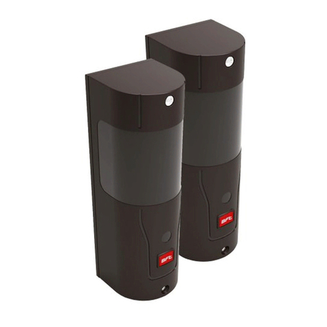
BFT ECOSOL User manual

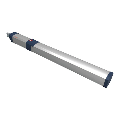
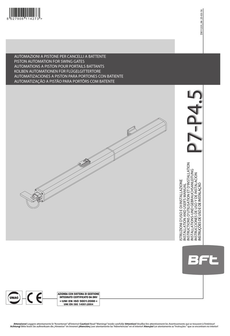
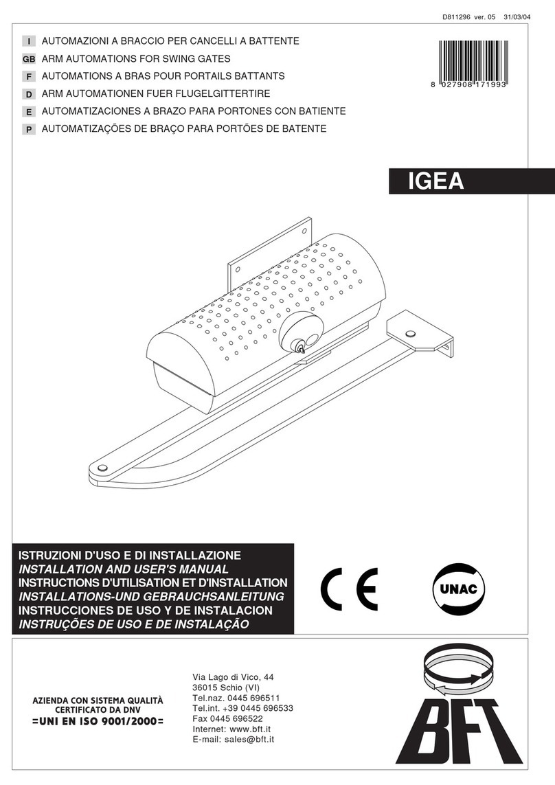
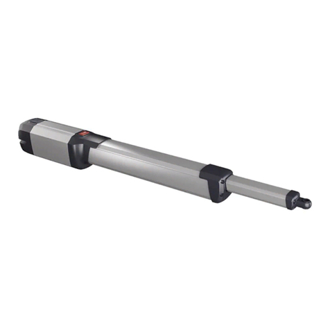
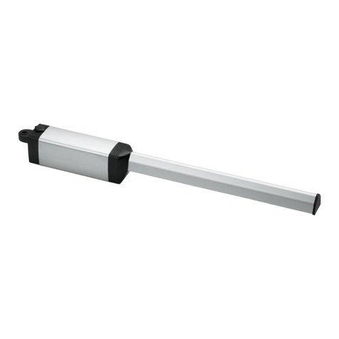
IGEA BTPHOBOS BT
COMPATIBLE WITH:
COMPATIBLE WITH:
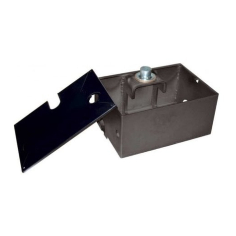
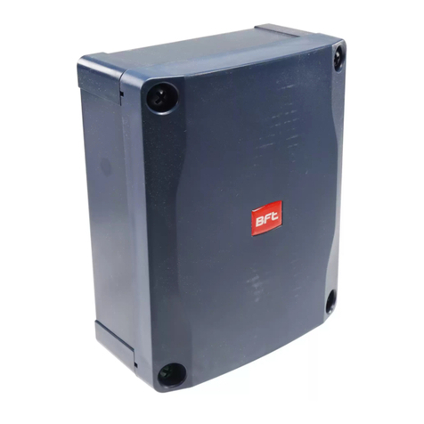
LIBRA UL-R PRE-WIRED ENCLOSURE
INSTALLATION MANUAL
ECOSOL BOOK 2 OF 2
VERSION 101116
www.BFTGateOpeners.com | (800) 878-7829

SECURITY BOLTS. To be used on solar panel
bracket. Once fixed and secured, akes the
re oval of the bolts virtually i possible. Great
for theft prevention. Part no. N999475
T-BOX WIRELESS KEYLESS ENTRY
KEYPAD. Self-contained, standalone access
keypad. 10 channels, 100 codes capacity.
Co patible with the ECOSOL built-in radio
receiver. Part no. P121019
RB WIRELESS WALLMOUNT CONTROL
STATION. Up to 4 syste s can be controlled
with this sleek 4 button station. For indoor or
outdoor use. Part no. P12101
STAINLESS STEEL POST MOUNT BRACKET.
For solar panel. Easy installation to post 2” to
4” in dia eter. Part no. N999473
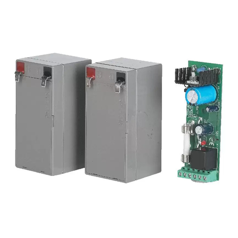
HIGH CAPACITY BATTERIES. 12V, 9 Ah. To
replace or add to existing syste . Up to 4
batteries can be installed in the enclosure.
They ust be added in pairs. Part no.
KBAT12V9AH
SOLAR PANEL. 10 watts, 24v. Up to 3 can be
installed to the syste for increased charging
capacity. Part no. N999471
ACCESSORIES
2
www.BFTGateOpeners.com | (800) 878-7829

PRODUCT PURCHASE AND INSTALLATION
This product is intended to only be installed by a qualified professional technician. The warranty on the
equip ent ay be voided if not properly installed. Warranty clai s should be directed to the co pany or
entity that sold the equip ent. Purchasing non-installed equip ent ay later hinder any warranty clai
because of conflict between the equip ent provider and the installer entity. It is highly reco ended for the
syste to be supplied and installed by a single entity.
SOLAR POWERED SYSTEM CONSIDERATIONS
The ECOSOL solar powered syste is intended for residential applications and light co ercial gate
operation with li ited cycles per day. While our syste can operate over 300 cycles and/or provide over 2
weeks of standby ti e on fully charged batteries, it needs enough standby ti e to fully recharge the
batteries or it will eventually run out of charge to operate the syste . We highly reco end to keep the
syste as si ple as possible and avoid adding accessories that draw current fro the batteries. The ECOSOL
interface board anages energy consu ption and powers down all co ponents, accessories and peripherals
that are not required to operate while the gate is fully closed or after 5 inutes of inactivity. For opti u
perfor ance, we reco end the following setup:
●One or two actuators (Phobos BT or Igea BT) connected to the ECOSOL syste .
●Two sets of photo-bea obstruction sensors.
●BFT radio trans itters and/or wireless keypads progra ed to the ECOSOL's built-in low consu ption
receiver.
●Auto atic closing ti er enabled.
Anyti e, additional accessories are added, it is suggested to increase the syste s charging capacity by
adding a solar panel. See page 15 for further infor ation.
EXISTING GATE CONDITION
Auto ation should be installed on a gate which is oving freely. Any issue with the s ooth opening or
closing of a gate will not be corrected by adding auto ation.
READ BEFORE INSTALLING
SYSTEM RECOMMENDATIONS 3
www.BFTGateOpeners.com | (800) 878-7829

ACCESSORIES
SYSTEM RECOMMENDATIONS
INSTALLATION CHECKLIST
IMPORTANT SAFETY INFORMATION
UL325 INSTALLATION RECOMENDATIONS
INSTALLATION SAFETY
OPERATIONAL SAFETY
THE SYSTEM
INSTALLING THE ENCLOSURE
POSITIONING THE SOLAR PANEL
MOUNTING THE SOLAR PANEL
WIRING THE SOLAR PANEL
ADDING SOLAR PANELS
INSTALLING THE BATTERIES
MOTOR CONNECTIONS
SAFETY DEVICES
OPENING DEVICES
CONTROL WIRING
ECOSOL SETTINGS
LIBRA UL-R PROGRAMMING
MAIN MENU
PARAMETERS SUB-MENU
LOGIC SUB-MENU
INITIAL PROGRAMMING
COMMON OPTIONS
RADIO TRANSMITTERS
MAINTENACE
TROUBLESHOOTING
DISPLAY GLOSSARY
.................................................................................................. 02
.......................................................................... 03
........................................................................... 05
................................................................. 06
....................................................... 07
.................................................................................... 08
..................................................................................... 09
.................................................................................................... 10
.......................................................................... 11
..................................................................... 12
........................................................................ 13
.............................................................................. 14
.................................................................................. 15
........................................................................... 16
................................................................................... 23
............................................................................................. 18
.......................................................................................... 19
........................................................................................... 20
.......................................................................................... 21
............................................................................ 22
..................................................................................................... 23
................................................................................. 24
............................................................................................ 25
................................................................................... 26
.......................................................................................... 27
.................................................................................... 28
................................................................................................ 29
........................................................................................ 30
........................................................................................ 31
TABLE OF CONTENTS4
www.BFTGateOpeners.com | (800) 878-7829

CAREFULLY READ ALL SAFETY INFORMATION. Pages 6 - 9
Install the gate operator(s) according to the installation anual (Book 1 of 2).
Deter ine the best location for your solar panel. Page 12
Secure ECOSOL enclosure to wall, colu n or post. Page 11.
Deter ine the orientation and inclination of the solar panel and install it. Pages 12 & 13.
Wire solar panel or panels to the ECOSOL syste Pages 14 & 15.
Install batteries. Page 16.
Connect otor wires to the ECOSOL syste . Page 23.
Connect obstruction sensing devices. Page 18.
Connect opening devices (if applicable). Page 19.
Connect other control devices (if applicable) Page 20.
Set the controller to SINGLE GATE OPERATION if needed. Page 26.
Perfor the AUTOSET. Page 26.
Set other features if needed. Page 27.
Adjust para eters if needed. Page 24.
Progra re ote controls and/or wireless keypad(s). Page 28.
Test all safety devices and features.
INSTALLATION CHECKLIST 5
www.BFTGateOpeners.com | (800) 878-7829

GATE AUTOMATION INSTALLATION SAFETY
While the anufacturer has designed the syste under strict safety standards, it is ulti ately the installers
responsibility to follow and co ply with national and local laws, codes and safety standards that apply to the
echanical, electrical and operational aspects of the gate auto ation syste . These include but are not li ited to:
safety standards established by entities like Underwriters Laboratory (UL), NFPA 70, or codes and laws stated by
corresponding state, county or unicipality.
While it ay not be co pulsory, we highly reco end following UL 325 safety standards.
UL 325 VEHICULAR GATE AUTOMATION CLASSIFICATION
This syste can be used in Class I, Class II and Class III applications.
•CLASS I – RESIDENTIAL VEHICULAR GATE OPERATOR - A vehicular gate operator (or syste ) intended for
use in a ho e of one-to four single fa ily dwelling, or a garage or parking area associated therewith.
•CLASS II – COMMERCIAL/GENERAL ACCESS VEHICULAR GATE OPERATOR - A vehicular gate operator (or
syste ) intended for use in a co ercial location or building such as a ulti-fa ily housing unit (five or
ore single fa ily units), hotel, garages, retail store, or other building servicing the general public.
•CLASS III – INDUSTRIAL/LIMITED ACCESS VEHICULAR GATE OPERATOR - A vehicular gate operator (or
syste ) intended for use in an industrial location or building such as a factory or loading dock area or
other locations not intended to service the general public.
•CLASS IV – RESTRICTED ACCESS VEHICULAR GATE OPERATOR - A vehicular gate operator (or syste )
intended for use in a guarded industrial location or building such as an airport security area or other
restricted access locations not servicing the general public, in which unauthorized access is prevented
via supervision by security personnel.
UL 325 ENTRAPMENT PROTECTION REQUIREMENTS
For all installation classes, it is required to properly adjust the inherent obstruction sensing syste (AUTOSET, page
26) and install warning signs on both sides of the gate, warning pedestrians of the dangers of the auto ated gate
syste . For Class I and Class II installations, it is required to add a non-contact device, such as
a photoelectric eye OR a contact device such as a gate edge. For Class III installations it is required to add a non-
contact device, such as a photoelectric eye, AND a contact device such as a gate edge OR an audio alar such as a
siren, horn or buzzer.
IMPORTANT SAFETY INFORMATION
www.BFTGateOpeners.com | (800) 878-7829

1. Install the gate operator only when:
a. The operator is appropriate for the construction and the usage class of the gate.
b. All openings of a horizontal slide gate are guarded or screened fro the botto of the gate to a
ini u of 4' (1.2 ) above the ground to prevent a 2-1/4" (6 c ) dia eter sphere fro passing
through the openings anywhere in the gate, and in that portion of the adjacent fence that the gate
covers in the open position.
c. All exposed pinch points are eli inated or guarded, and guarding is supplied for exposed rollers.
2. The operator is intended for installation only on gates used for vehicles. Pedestrians ust be supplied with
a separate access opening. The pedestrian access opening shall be designed to pro ote pedestrian usage.
Locate the gate such that persons will not co e in contact with the vehicular gate during the entire path of
travel of the vehicular gate.
3. The gate ust be installed in a location so that enough clearance is supplied between the gate and
adjacent structures when opening and closing to reduce the risk of entrap ent. Swinging gates shall not
open into public access areas.
4. The gate ust be properly installed and work freely in both directions prior to the installation of the gate
operator.
5. Controls intended for user activation ust be located at least six feet (6') away fro any oving part of the
gate and where the user is prevented fro reaching over, under, around or through the gate to operate the
controls. Outdoor or easily accessible controls shall have a security feature to prevent unauthorized use.
6. The Stop and/or Reset (if provided separately) ust be located in the line-of-sight of the gate. Activation of
the reset control shall not cause the operator to start.
7. A ini u of two (2) WARNING SIGNS (supplied with the gate operator) shall be installed, one on each side
of the gate where easily visible.
8. For a gate operator utilizing a non-contact sensor:
a. Reference owner’s anual regarding place ent of non-contact sensor for each type of application.
b. Care shall be exercised to reduce the risk of nuisance tripping, such as when a vehicle trips the sensor
while the gate is still oving.
c. One or ore non-contact sensors shall be located where the risk of entrap ent or obstruction exists,
such as the peri eter reachable by a oving gate or barrier.
9. For a gate operator utilizing a contact sensor such as an edge sensor:
a. One or ore contact sensors shall be located where the risk of entrap ent or obstruction exists, such
as at the leading edge, trailing edge and post ounted both inside and outside of a vehicular horizontal
slide gate.
b. One or ore contact sensors shall be located at the botto edge of a vehicular vertical lift gate.
c. A hard wired contact sensor shall be located and its wiring arranged so the co unication between the
sensor and the gate operator is not subject to echanical da age.
d. A wireless contact sensor such as the one that trans its radio frequency (RF) signals to the gate
operator for entrap ent protection functions shall be located where the trans ission of the signals are
not obstructed or i peded by building structures, natural landscaping or si ilar obstruction. A wireless
contact sensor shall function under the intended end-use conditions.
e. One or ore contact sensors shall be located on the inside and outside leading edge of a swing gate.
Additionally, if the botto edge of a swing gate is greater than 6" (152 ) above the ground at any
point in its arc of travel, one or ore contact sensors shall be located on the botto edge.
f. One or ore contact sensors shall be located at the botto edge of a vertical barrier (ar ).
UL325 INSTALLATION RECOMMENDATIONS 7
www.BFTGateOpeners.com | (800) 878-7829

GENERAL SAFETY
WARNING! An incorrect installation or i proper use of the product can cause da age to persons, ani als or
property.
• Auto ation should be installed on a gate which is oving freely. Any issue with the s ooth opening of closing of a
gate will not be corrected by adding auto ation.
• Scrap packing aterials (plastic, cardboard, polystyrene etc) according to the provisions set out by current
standards. Keep nylon or polystyrene bags out of children’s reach.
• Keep this instruction anual for future reference.
• This product was exclusively designed and anufactured for the use specified in the present docu entation. Any
other use not specified in this docu entation could da age the product and be dangerous.
• The Co pany declines all responsibility for any consequences resulting fro i proper use of the product, or use
which is different fro that expected and specified in the present docu entation.
• Do not install the product in explosive at osphere.
• The Co pany declines all responsibility for any consequences resulting fro failure to observe Good Technical
Practice when constructing closing structures (door, gates etc.), as well as fro any defor ation which ight occur
during use.
• Follow and co ply with national and/or local electrical codes when perfor ing any electrical installation.
• Disconnect the electrical power supply before carrying out any work on the installation. Also disconnect any buffer
batteries, if fitted.
• Fit all the safety devices (photocells, electric edges etc.) which are needed to protect the area fro any danger
caused by squashing, conveying and shearing, according to and in co pliance with the applicable directives and
technical standards.
• It is reco ended to position at least one lu inous signal indication device (blinker) where it can be easily seen
for additional safety
• The Co pany declines all responsibility with respect to the auto ation safety and correct operation when other
anufacturer’s co ponents are used.
• Only use original parts for any aintenance or repair operation.
• Do not odify the auto ation co ponents, unless explicitly authorized In writing by the Co pany.
• Instruct the product user about the control syste s provided and the anual opening operation in case of
e ergency.
• Anything which is not expressly provided for in the present instructions, is not allowed.
• Installation ust be carried out using the safety devices and controls prescribed by the UL 325 Standard.
CHECKING INSTALLATION
Before the auto ated device is finally put into operation, perfor the following checks eticulously:
• Make sure all co ponents are fastened securely.
• Check that all safety devices (photocells, pneu atic safety edge, etc.) are working properly.
• Check the e ergency operation control device.
• Check opening and closing operations with the control devices applied.
• Check the electronic logic for nor al (or personalized) operation in the control panel.
ADJUSTING OPERATING FORCE
WARNING: Operating force is adjusted with extre e precision by eans of the control unit’s electronic control.
Operation at the end of travel is adjusted electronically in the control panel. To provide good anti-crush safety, the
operating force ust be slightly greater than that required to ove the leaf both to close and to open it.
CONTROL
There are various options when it co es to the control syste ( anual, re ote control, access control with
agnetic badge, etc.) depending on the installation’s needs and characteristics. See the relevant instructions for
the various control syste options. People due to use the auto ated device ust be instructed how to control and
use it.
INSTALLATION SAFETY
8
www.BFTGateOpeners.com | (800) 878-7829

The installer is responsible for communicating the following information to the end-user:
This product has been designed and built solely for the purpose indicated herein. Uses not conte plated herein
ight result in the product being da aged and could be a source of danger.
The Fir disclai s all responsibility resulting fro i proper use or any use other than that for which the product
has been designed, as indicated herein, as well as for failure to apply Good Practice in the construction of entry
syste s (doors, gates, etc.) and for defor ation that could occur during use. If installed and used correctly, the
auto ated syste will eet the required level of safety. Nonetheless, it is advisable to observe certain rules
of behavior so that accidental problems can be avoided:
•Keep adults, children and property out of range of the auto ated syste , especially while it is operating.
•Operate the syste when the full path of the gate is within sight.
•It is essential to frequently check that all safety devices are in good working condition.
•This application is not eant for use by people (including children) with i paired ental, physical or
sensory capacities, or people who do not have suitable knowledge, unless they are supervised or have been
instructed by people who are responsible for their safety.
•Children ust be supervised to ensure they do not play with the syste . Keep re ote controls or other
control devices out of reach of children in order to avoid the auto ated syste being operated
inadvertently.
•Check the syste frequently, especially hinges, cables, springs or supports, to detect any loss of balance
and signs of wear or da age.
•When cleaning the outside or perfor ing other aintenance work, always cut off ains power.
•Keep the photocells’ optics and illu inating indicator devices clean. Check that no branches or shrubs
interfere with the safety devices (photocells).
•Do not use the auto ated syste if it is in need of repair. In the event of a alfunction, cut off the power,
activate the e ergency release to allow access and call in qualified technical personnel (professional
installer).
•If the auto ated syste requires work of any kind, e ploy the services of qualified personnel (professional
installer).
•Anything that is not explicitly provided for in these instructions is not allowed.
•The operator’s proper operation can only be guaranteed if the infor ation given herein is co plied with.
The Fir shall not be answerable for da age caused by failure to co ply with the installation rules and
instructions featured herein.
•Have the co plete syste checked including all safety devices by a qualified professional technician at
least once a year.
Descriptions and illustrations herein are not binding. While we will not alter the product’s essential features, the
Fir reserves the right, at any ti e, to ake those changes dee ed necessary to i prove the product fro a
technical, design or co ercial point of view, and will not be required to update this publication accordingly.
OPERATIONAL SAFETY 9
www.BFTGateOpeners.com | (800) 878-7829

(2) 12V, 9 Ah batteries
30% ore capacity than standard 7 Ah batteries
TEST BUTTON
Triggers the START
input for the
installer's and
service technician's
convenience.
ECOSOL INTERFACE BOARD
●Regulates the power fro the solar panel(s)
●Monitors battery charge
●Charges batteries
●Manages power. Shuts down all co ponents not needed
when syste is not in use
●Processes starting co ands. Powers up the syste and
relays signals once syste is operational
●Receives radio co ands. Has a built-in low power
consu ption radio receiver with a 64 trans itters capacity,
eli inating the need for external receivers
LIBRA UL-R CONTROLLER
●Controls (2) Phobos BT or Igea BT operators.
●Self learning torque settings.
●Adjustable independent gate leaf delay
THREADED HOLES
For the installation of (2)
Diablo Controls DSP-6LP
or DSP-7LP
TERMINAL BLOCKS
Clearly labeled, easy
access ter inal block
connections
THE SYSTEM10
www.BFTGateOpeners.com | (800) 878-7829

ATTACHING THE ENCLOSURE
Fasten the ECOSOL enclosure to a wall, colu n or post
using the 4 ounting holes on the flange on the back
of the enclosure. DO NOT DRILL THROUGH THE
INTERIOR OF THE ENCLOSURE.
15 ft. ax cable length
ENCLOSURE LOCATION
Because the axi u length of the cable that connects the solar panel and the ECOSOL enclosure
is li ited to 15 feet, it is ore i portant that the final location of the enclosure is close to the
location of the solar panel than to the location of the gate operators.
INSTALLING THE ENCLOSURE 11
www.BFTGateOpeners.com | (800) 878-7829

Solar panel MUST FACE SOUTH
SOLAR PANEL LOCATION - The solar panel ust be located
on a unshaded area away fro trees and/or tall structures that
ay cast a shadow during any ti e of the day or year. It is
extre ely i portant to be aware that the sun has a lower path
in the sky during the winter onths and objects that ay not
cast shadows over a certain area during su er, ay cast the
during the winter. Also, trees ay grow and cast larger shadows
over ti e.
SOLAR PANEL INCLINATION - The degrees of inclination in
reference to ground level should be set according to your
location and the illustration below. Example: If installed in the
state of Georgia, the panel ust have a 40° inclination. If
installed in Wyo ing the panel ust have a 50° inclination.
WA
WA ME
OR
OR
CA
NV
ID
ID
UT
AZ
MT
MT
WY
CO
NM
TX
TX
OK
KS
NE
SD
SD
ND
ND
MN
MN
IA
MO
AR
WI
WI
IL
LA
MS AL GA
FL
FL
SC
NC
TN
KY
IN OH
MI
MI
NY
NY
PA
VA
WV MD
DE
NJ
MA
MA
VT
VT NH
NH
CT
CT
RI
50°
50°
40°
40°
45°
45°
35°
35°
55°
55°
ɑ
OTHER COUNTRIES:
30° Mexico, Ja aica, La Espalier, Puerto Rico, U.S. and British Virgin Islands.
25° Guate ala, Honduras, El Salvador.
20° Nicaragua, Costa Rica, Pana a.
DEGREES OF INCLINATION
S
S
POSITIONING THE SOLAR PANEL12
www.BFTGateOpeners.com | (800) 878-7829

Secure “L” brackets to panel's fra e
Attach ounting bracket to ounting surface.
The hardware allows for wall ount or top
ount installation
Mounting screws or
anchors not included
Brackets can be attached at different heights on the
panel to acco odate different installation
conditions
2” to 4” dia eter post
Optional stainless steel adjustable post ount
bracket is available. Part no. N999473
Attach the panel to the ounting bracket
Nylon lock nut
Bolt1
2
3
4
Pressure
washer
3/4”
Flat washer
MOUNTING THE SOLAR PANEL 13
www.BFTGateOpeners.com | (800) 878-7829

●Re ove the 4 screws that
hold the cover to the solar
panel ter inal block.
●Run the cable through (1) of
the connector fittings.
●Connect the black wire to
the left (negative) ter inal
and the red wire to the right
(positive) ter inal.
Connect the wires fro the solar
panel to the ter inals labeled SOLAR
PANEL – and SOLAR PANEL +
FROM SOLAR PANEL
15 ft. ax cable length
CONNECT CABLE TO SOLAR PANEL
RUN THE CABLE TO THE ECOSOL ENCLOSURE
CONNECT CABLE TO TERMINAL STRIP
1
2
3
USE 1 AWG OR BETTER, STRANDED WIRES
WIRING THE SOLAR PANEL14
www.BFTGateOpeners.com | (800) 878-7829

To Ecosol EnclosureTo next solar panel
Up to (3) 10 watts, 24v panels can be connected to the ECOSOL.
1st panel 2nd panel (optional) 3rd panel (optional)
ECOSOL
The solar panels ust be connected in a parallel
daisy chain where the black wires will only be
connected to the negative ter inal and the red
wire will only be connected to the positive
ter inal on the solar panels.
KEEP THE CABLES AS SHORT AS POSSIBLE!!
The wires should be stranded 16 AWG or better and no longer than 15ft.
(35W axi u total capacity)
ADDING SOLAR PANELS 15
www.BFTGateOpeners.com | (800) 878-7829

When adding batteries...
● Install (4) new batteries – Never ix used and new
batteries
● Make sure they have the same rating – Batteries ay
have the sa e physical size but have different
characteristics (volts and a pere-hours)
● Equalize the charge – all 4 batteries ust be within 0.7
volts of each other. An easy way of acco plishing this is by
fully charging the individually before installing.
● Connect to ECOSOL - The pri ary pair of batteries ust
be connected to JP15(-) and JP1 (+) while the secondary
pair ust be connected to JP23(+) and JP18(-).
● Dipswitch 1 on the ECOSOL board MUST be turned on
when secondary pair of batteries are connected
The ECOSOL /Libra is shipped with the batteries leads pre-installed.
The negative (black) lead is not connected to prevent discharge
before installation. To power up the syste , connect the black lead to
the negative battery ter inal
The ECOSOL/Libra enclosure can hold up to (2) pairs (4
total) batteries for greater energy storage capacity. The
battery brackets ust be re oved and the batteries
ust be rotated longways in order to fit the inside the
enclosure.
PRIMARY PAIR
SECONDARY PAIR
WARNING
POWER UP
ADDING MORE BATTERIES
INSTALLING THE BATTERIES
1
www.BFTGateOpeners.com | (800) 878-7829

BFT PHOBOS BT AND
IGEA BT GATE
OPERATORS ONLY
When installing dual gate where the gates overlap (or has a lock echanis ), it is i portant that the
motor that needs to open first is wired to MOTOR 2 ter inals.
During the open cycle, MOTOR 2 starts first (MOTOR 1 has a delayed open start). During the close
cycle, MOTOR 1 starts first (MOTOR 2 has a delayed close start).Both delays can be independently adjusted
fro 1 to 29 seconds. Please refer to page 24
24 for further instructions.
When installing a single leaf gate operator, the otor leads ust be wired to MOTOR 2 ter inals and
LIBRA controller ust be configured to single gate operation. Please refer to page 26 for further
instructions.
SINGLE GATE OPERATION
DUAL GATE OPERATION
MOTOR 2
OPENS FIRST
CLOSES SECOND
MOTOR 1
OPENS SECOND
CLOSES FIRST
USE 1 AWG OR BETTER, STRANDED WIRES
MOTOR CONNECTIONS 17
www.BFTGateOpeners.com | (800) 878-7829

Photo-beam senso s should only be used as safety devices, NEVER as f ee exit devices.
NOTE: If mo e than one device needs to be wi ed to the Safety input, they must be wi ed in se ies
PHOTO BEAM AND SAFETY EDGE SENSORS
24VDC
NORMALLY CLOSED
DURING NO OBSTRUCTION
MAGNETIC LOOP DETECTORS
24VDC
NORMALLY CLOSED
DURING NO DETECTION
Loop detecto s must ALWAYS BE POWERED to ensu e p ope detection.
Avoid the utilization of loop detectors. They decrease the standby ti e as well as the cycles per day.
They also increase the battery charge ti e. If loop detectors are a ust in your installation, look for
low power consu ption loop detectors such as Diablo Controls odels DSP- LP and DSP-7LP.
ADDING AN ADDITIONAL SOLAR PANEL IS RECOMMENDED.
MULTIPLE SAFETY DEVICES
REMOVE FACTORY
INSTALLED JUMPER
REMOVE FACTORY
INSTALLED JUMPER
SAFETY DEVICES18
www.BFTGateOpeners.com | (800) 878-7829

WIRELESS
24VDC
OPEN DEVICES
NORMALLY OPEN CONTACTS
Avoid the utilization of external opening devices that require to be powered off the ECOSOL syste .
They decrease the standby ti e as well as the cycles per day capacity. They also increase the battery
charge ti e. If a “free exit” device is a ust in your installation, look for low power consu ption loop
detectors such as Diablo Controls odels DSP- LP and DSP-7LP or other low consu ption devices.
ADDING AN ADDITIONAL SOLAR PANEL IS RECOMMENDED.
The ECOSOL syste has a built-in, low power consu ption, radio receiver for BFT re ote
controls and wireless keypads. Any additional opening device powered off the syste will
decrease the syste 's battery perfor ance
MITTO 2
2 button re ote control
MITTO 4
4 button re ote control
T-BOX
Battery operated wireless keypad
HARD WIRED
SEE PAGE 28 FOR PROGRAMMING INSTRUCTIONS
OPENING DEVICES 19
www.BFTGateOpeners.com | (800) 878-7829

NOTE: If mo e than one device needs to be wi ed to the STOP input, they must be wi ed in se ies
START / CLOSE INPUT
STOP / RESET BUTTON
3-BUTTON STATION (open, stop, close)
The Start/Close input can be used for a single push button operation to open, stop and close co ands
The Stop button also resets the controller if two consecutive physical obstructions are detected.
This is a NORMALLY CLOSED contact. The factory installed ju per ust be re oved for stop
button to operate.
REMOVE FACTORY
INSTALLED JUMPER
A 3-button station can be hard-wired using the START/CLOSE as close input. This input ust be defined
as CLOSE ONLY INPUT at the controller. See page 25 (START-CLOSE) for directions.
CONTROL WIRING20
www.BFTGateOpeners.com | (800) 878-7829
Table of contents
Other BFT Gate Opener manuals

BFT
BFT SUB BT User manual

BFT
BFT PHOBOS L BT User manual

BFT
BFT ELI 250 BT User manual

BFT
BFT PHOBOS N-PHOBOS N L User manual

BFT
BFT PHOBOS N BT User manual

BFT
BFT GIUNO ULTRA BT A20 User manual

BFT
BFT DEIMOS BT A 600 User manual

BFT
BFT PHOBOS BT B 25 User manual

BFT
BFT PHOBOS AC A25 230 User manual

BFT
BFT FCS User manual