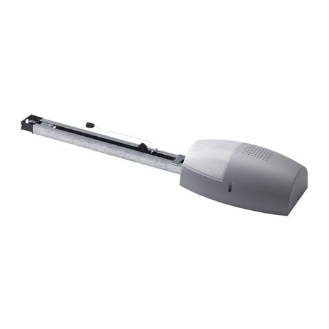
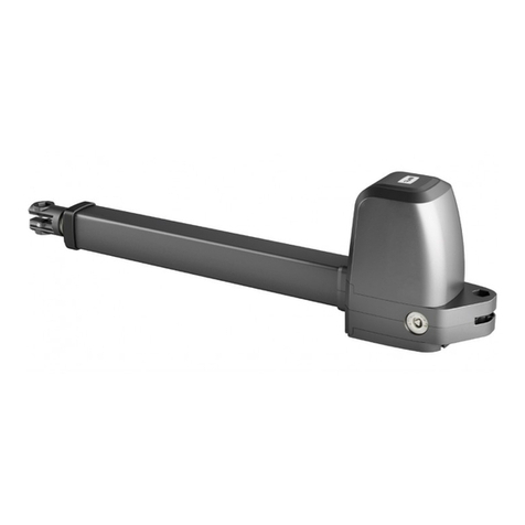
JOINT - Ver. 02 -
9
D811292_02
2) GENERAL OUTLINE
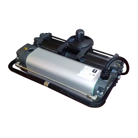
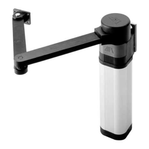
This controller is suitable for residential use and has been designed for
swing gates with particularly large gate posts. The drive arm, built with a
special anti-shearing shape, allows the leaves to be moved when the
controller is considerably out of place with respect to the fulcrum of the
leaves. The non-reversible electro-mechanical gearmotor maintains the
stop during closing and opening. The release lever, fitted in each controller
and situated inside the door fitted with personalised key, allows the manual
manoeuvre to be easily carried out.
WARNING! The installation, the maintenance and the repair should be
done by responsible and qualified persons with an updated knowledge of
the current safety standards. It’s strictly forbidden to service the automation
when the power is on.
ATTENTION! The JOINT model controller is not equipped with mechanical
torque adjustment. It is compulsory to use a control panel of the same
manufacturer, in compliance with the basic safety requirements of directives
73/23/CEE, 89/336/CEE, 89/37/CEE equipped with appropriate electric
adjusment of the torque.
3) TECHNICAL SPECIFICATIONS
Voltage:....................................................................... 120V±10% 50Hz (*)
Motor: ....................................................................Single-phase 1400min-1
Power: ................................................................................................300W
Absorption: ........................................................ 1.7A (230V); 3,4A (120V)
Capacitor: ..................................... 10µF 450V (230V); 40µF 250V (120V)
Insulation class: ........................................................................................ F
Thermal protection: ........................... 266°F ........... (130°C) self-resetting
Lubrication: ................................................................... Permanent grease
Reduction ratio: ................................................................................. 1/812
Output revs.: .......................................................................... 1.7 min-1max
Output shaft: ................................................................. 20x20 hollow shaft
Opening time 90°: ................................................................................. 15s
Torque provided: ................. 320Nm (~32kgm)........236.01lbf/ft (~70.54lb)
Max. leaf weight and length:
for 2.5m leaf length................ 2000N (~200kg)........449.61 lbf (~440.92lb)
for 2m leaf length ................... 2500N (~250kg).........562.02lbf (~551.15lb)
Impact reaction: ................................... Electric clutch (with control panel)
Drive: ..........................................................................................Lever arm
Stopping:...................................................... Built-in electric limit-switches
Manual manoeuvre: ........................................ Door with personalised key
Number of manoeuvres: ................................................................ 100/24h
Working temperature: ................... -15 ÷+60 C..........................°59÷140°F
Protection: ......................................................................................... IP 44
Controller weight: ....... 160N (~16kg) 35.96 lbf .........................(~35.27 lb)
Dimensions: ..................................................................................See fig.1
*Special supply voltages on request buckle “M” of the operator. Refer to the
relevant instruction manual for connection of the control panel.
4) INSTALLATION OF AUTOMATION
Preliminary checks
Check:
- That the structure of the gate is rigid and strong enough. The fixing
position should be assessed according to the structure of the leaf. In any
case, the manoeuvring arm must push against a reinforced point in the
leaf (fig.2).
- That the leaves move manually for the whole of their stroke. If a new gate
is not being installed, check whether its components are worn.
Repair or replace any worn or damaged parts.
Automation reliability and safety are directly influenced by the condition
of the gate’s structure.
5) FIXING OF SUPPORTING PLATE (Fig.2)
The controller is supplied complete with anchoring bracket and lever arm.
Once the reinforcement point of the leaf has been identified with the gate
closed,drawan imaginary horizontal line from the centre of the reinforcement
point to the gate post (fig.2). Position the anchoring bracket according to the
values given in fig. 2 for openings of up to 90°or in fig.3 for openings greater
than 90°up to a maximum of 125°.
The bracket fixing position must be flat and parallel to the leaf. Use screws
or expansion bolts which are suited to the type of gate post. If the surface
of the gate post is not regular, use expansion bolts with studs so that the
parallel plate of the leaf can be adjusted (fig.4).
- Fasten the gearmotor to the gate post using the 4 screws, pointing the
gearmotor to the left or the right (fig.5).
- Assemble the lever arm as shown in fig.6.
DX= assembly on the right leaf
SX= assemby on the left leaf
Choose the most suitable position of ‘F’ bracket for the fastening to the leaf.
- Insert the square of the first lever in the output shaft of the gearmotor and
fasten it (fig.7).
- Release the controller by activating the release lever so that the arm can
move easily (see the “EMERGENCY MANOEUVRE” paragraph).
- The correct position for the controller arm is shown in fig.8. The leaf
fixing point “A” can be identified by positioning the arm so that it is in
accordance with the distance shown in fig.8.
- Fix the angular towing bar “A” to the leaf by welding or using screws.
- With the controller released, check the correct movement of the arm.
- Repeat the same operation for the other leaf, if installed.
6) ELECTRICAL INSTALLATION SET-UP
Arrange the electrical installation as shown in fig.9.
The power supply connections must be kept separate from the auxiliary
connections (photocells, sensitive edge, etc.). Fig.9 shows the cross-
section and the number of connections. CAUTION! Connection to the
mains must be carried out using the type of multipolar cable specified in the
standards (UL1015). In fig.10 you will find the junction-box of the operator
and the position of the cable holder which should be fixed with an adequate
tightening of the bolt. In case the motor tours in the opposite side, you
should invert the running buckle "M" of the operator. Refer to the relevant
instruction manual for connection of the control panel.
7) LIMIT SWITCH ADJUSTMENT
- Remove the casing of the limit switches.
- Identify the limit switches following fig.12 for the right-hand controller
and following fig.11 for the left-hand controller.
- Adjustthe opening and closing cams respectively with thegatecompletely
open and completely closed.
- Turn the identified cam until the intercepting limiting microswitch triggers
and lock the cam in position by tightening the screw.
- Make sure that limit switch intervention is correct and refit the cover
which was previously removed.
- Fit the casing.
- If the control unit has working time adjustment (TW), this should be
adjusted to a value which is slightly higher than the intervention of the
controller limit switches.
8) ADJUSTMENT OF LEAF PHASE DISPLACEMENT
In case of gates with two leaves, the control panel should include a delay
setting function on closing of the second leaf to guarantee a correct closing
manoeuvre. For the wiring of the motor which should close with a slight
delay, refer to the instructions for the control panel installed.
9) MOTOR TORQUE ADJUSTMENT
The adjustment of the motor torque (anti-squashing) is performed on the
control panel. See control unit instruction manual.
The adjustment should be set for the minimum force required to carry out
the opening and closing strokes completely observing, however, the limits
of the relevant standards in force.
CAUTION! Excessive torque adjustment may jeopardise the anti-squash
safety function. On the other hand insufficient torque adjustment may not
guarantee correct opening or closing strokes.
10) EMERGENCY MANOEUVRE
The emergency manoeuvre can be carried out form the inside by activating
the appropriate lever on each controller, as in fig.13, and pushing the panel
by hand. To restore motorised operation, turn the lever to its initial position
and close the hatch having a personalised key.
11) AUTOMATION CHECK
Before allowing the automation to be used normally, carry out the following
procedure very carefully:
- Check the correct functioning of all safety devices (limit microswitches,
photocells, sensitive edges etc.).
- Check that the thrust (anti-squash) force of the leaf is within the limits set
by current regulations.
- Check the manual opening command.
- Check the opening and closing operations with the control devices in use.
- Check the standard and customised electronic functioning logic.
12) AUTOMATION OPERATION
Since the automation can be remote-controlled by means of a remote
control device or a start button, and so out of sight, the good working order
of all the safety devices should be checked regularly. In the event of any
anomalous functioning of the safety devices, consult a specialised
technician immediately. Keepchildrenatasafe distance from the automation
operation area.
INSTALLATION MANUAL ENGLISH
