BFT ELI 250 BT User manual

D811479 ver. 04 15-06-07
I
GB
F
D
E
P
ISTRUZIONI D'USO E DI INSTALLAZIONE
INSTALLATION AND USER'S MANUAL
INSTRUCTIONS D'UTILISATION ETD'INSTALLATION
INSTALLATIONS UND GEBRAUCHSANLEITUNG
INSTRUCCIONES DE USOY DE INSTALACION
INSTRUÇÕES DE USO E DE INSTALAÇÃO
Via Lago di Vico, 44
36015 Schio (VI)
Tel.naz. 0445 696511
Tel.int. +39 0445 696533
Fax 0445 696522
Internet: www.bft.it
E-mail: [email protected]
8027908 2 8 3 0 2 3
AUTOMAZIONE ELETTROMECCANICA INTERRATA PER CANCELLI A BATTENTE
ELECTROMECHANIC AUTOMATIONS FOR SWING GATES
AUTOMATISME ELECTROMECANIQUE ENTERRÉ POUR PORTAILS A VANTAUX
ELEKTROMECHANISCHER ANTRIEB FÜR FLÜGELGITTERTORE
AUTOMATISMO ELECTROMECANICO SOTERRADO PARA CANCELAS BATIENTES
AUTOMATIZAÇÃO ELECTROMECNICA SUBTERRNEA PARA PORTÕES COM BATENTE
ELI 250 BT

2- ELI 250 BT - Ver. 04
D811479_04

ELI 250 BT - Ver. 04 - 3
D811479_04
MANUALE D’USO ITALIANO
Nel ringraziarVi per la preferenza accordata a questo prodotto, la ditta è certa che da esso otterrete le prestazioni necessarie al Vostro uso.
Leggete attentamente l’opuscolo ”Avvertenze” ed il ”Libretto istruzioni” che accompagnano questo prodotto, in quanto forniscono importanti indicazioni
riguardanti la sicurezza, l’installazione, l’uso e la manutenzione.Questo prodotto risponde alle norme riconosciute della tecnica e delle disposizioni rela-
tive alla sicurezza.Confermiamo che è conforme alle seguenti Direttive Europee: 86/336/CEE, 73/23/CEE (e loro modifiche successive).AVVERTENZE!
Qualunque intervento sui componenti dell’automazione deve essere eseguito da personale qualificato (installatore).
1) GENERALITÀ
L’attuatore elettromeccanico ELI 250 BT è la soluzione ideale per applicazioni interrate sottocardine.L’attuatore è realizzato con un unico riduttore mono-
blocco a tenuta stagna.La posizione sottocardine mantiene l’estetica del cancello intatta e rende l’automazione praticamente invisibile.Una volta installata
la cassa portante, il cancello è operativo anche senza montare l’attuatore che può essere inserito successivamente.In caso di manutenzione, questo tipo
di cassa consente di togliere l’attuatore senza smontare l’anta del cancello. L’attuatore ELI 250 BT è applicabile a qualsiasi tipo di cancello a battente
rispondente ai valori riportati nella tabella dei Dati tecnici. La forza di spinta si regola sulla centralina (vedi manuale specifico). Il funzionamento a fine
corsa è regolato da sensori magnetici di fine corsa e da fermi meccanici situati all’interno della cassa di fondazione.
ATTENZIONE! L’attuatore mod. ELI 250 BT non è dotato di regolazione meccanica di coppia. É obbligatorio utilizzare un quadro di comando
del medesimo costruttore, conforme ai requisiti essenziali di sicurezza delle direttive 73/23/CEE, 89/336/CEE, 98/37/CEE e dotato di adeguata
regolazione elettrica della coppia.
2) MANOVRA DI EMERGENZA
Lo sblocco di emergenza si effettua agendo, con l’apposita chiave in dotazione, sul gruppetto sblocco situato sotto il cancello sulla parte sporgente della
leva-perno.Per sbloccare, inserire la chiave nel triangolo di sblocco e ruotare la chiave verso l’indicazione del lucchetto aperto per circa 90° (fig.1).
Se l’anta è dotata di elettroserratura, sbloccare anche l’elettroserratura. Spingere manualmente l’anta per aprire/chiudere il cancello. Per ripristinare
l’operazione motorizzata, riposizionare il cancello allineato con la leva che porta il gruppo blocco e girare la chiave verso l’indicazione del lucchet-
to chiuso (fig.1) avendo cura di controllare l’avvenuto aggancio dell’anta. Riporre la chiave di sblocco anta (e dell’elettroserratura se presente) in luogo
conosciuto agli utilizzatori.
3) USO DELL’AUTOMAZIONE
Poichè l’automazione può essere comandata a distanza mediante radiocomando o pulsante di Start, e quindi non a vista, è indispensabile controllare
frequentemente la perfetta efficienza di tutti i dispositivi di sicurezza. Per qualsiasi anomalia di funzionamento, intervenire rapidamente avvalendosi di
personale qualificato. Si raccomanda di tenere i bambini a debita distanza dal raggio di azione dell’automazione.
4) DEMOLIZIONE
L’eliminazione dei materiali va fatta rispettando le norme vigenti.Nel caso di demolizione dell’automazione non esistono particolari pericoli o rischi derivanti
dall’automazione stessa. È opportuno in caso di recupero dei materiali, che vengano separati per tipologia (parti elettriche - rame - alluminio - plastica
- ecc.).
5) SMANTELLAMENTO
Nel caso l’automazione venga smontata per essere poi rimontata in altro sito, bisogna:
• Togliere l’alimentazione e scollegare tutto l’impianto elettrico.
• Togliere il motoriduttore dalla base di fissaggio.
• Smontare il quadro di comando se separato e tutti i componenti dell’installazione.
• Nel caso alcuni componenti non possano essere rimossi o risultino danneggiati, provvedere alla loro sostituzione.
6) MALFUNZIONAMENTO: CAUSE E RIMEDI
Per qualsiasi anomalia di funzionamento non risolta, togliere l’alimentazione al sistema e chiedere l’intervento di personale qualificato (installatore).
Nel periodo di fuori servizio, attivare lo sblocco manuale per consentire l’apertura e la chiusura manuale. In questo periodo, per mantenere il blocco in
chiusura, provvedere a mantenerlo chiuso mediante catena e lucchetto.
Fig. 1
2
1
Max. 90°

4- ELI 250 BT - Ver. 04
D811479_04
USER’S MANUAL
ENGLISH
Thank you for buying this product, our company is sure that you will be more than satisfied with the performance of the product.This product is supplied
with a “Warnings”leaflet and an “Instruction manual”.These should both be read carefully as they provide important information about safety, installation,
operation and maintenance.This product complies with recognised technical standards and safety regulations.We declare that this product is in conformity
withthefollowingEuropeanDirectives:89/336/EECand73/23/EEC(andsubsequentamendments).WARNINGS:Anyassistancerequiredonautomation
components must be carried out by a qualified technician (installer).
1) GENERAL OUTLINE
The ELI 250 BT electromechanical actuator is the ideal solution for underground hinge-pivot installation.The actuator consists of a perfectly sealed single-
block reduction gear.The under hinge-pivot position maintains the aesthetic appearance of the gate and practically hides the automation system.
Oncethebearing case is installed, the gate can be operatedeven without fitting the actuator which can be inserted later.Whenmaintenanceisrequired, this
type of case allows the actuator to be taken out without removing the gate leaf.The ELI 250 BT actuator can be fitted to any type of swing gate which meets
the values shown in the ”Technical Specifications” table.The pushing force is set on the control unit (see specific manual).The end-of-stroke operation
is controlled by special end-of-stroke magnetic sensors and by mechanical stop blocks located inside the foundation case.CAUTION!The actuator mod.
ELI 250 BT is not provided with mechanical torque adjustment. It is compulsory to use a control board of the same manufacturer, according to
the basic safety requirements of directives 73/23/CEE, 89/336/CEE, 98/37/CEE and provided with adequate electric torque adjustment.
2) EMERGENCY MANOEUVRE
Emergency release is obtained by using the key provided, on the release unit which is located under the gate, on the protruding section of the lever-pivot.
To release, insert the key in the release triangle and turn it by about 90° in the direction shown by the open-padlock symbol (fig.1). If the leaf is equipped
with an electric lock, release the electric lock as well.To open/close the gate, push it manually.To restore motor-driven operation, reposition the gate by ali-
gning it with the lever bearing the lock unit, and turn the key in the direction shown by the closed-padlock symbol (fig.1) checking that engagement is correctly
restored. Keep the leaf release key (and that of the electric lock, if any) in a place which is known to the users.
3) AUTOMATION OPERATION
Since the automation system can be remotely controlled by means of a radio control device or a Start button, and therefore out of sight, all safety devices
must be frequently checked in order to ensure their perfect efficiency. In the event of any anomalous operation, request immediate assistance from qualified
personnel. Children must be kept at a safe distance from the automation operation area.
4) SCRAPPING
Materials must be disposed of in conformity with the current regulations.
In case of scrapping, the automation devices do not entail any particular risks or danger. In case of recovered materials, these should be sorted out by
type (electrical components, copper, aluminium, plastic etc.).
5) DISMANTLING
When the automation system is disassembled to be reassembled on another site, proceed as follows:
• Disconnect the power supply and the entire electrical installation.
• Remove the gearmotor from its fixing base.
• Disassemble the control panel, if separate, and all installation components.
• In the case where some of the components cannot be removed or are
damaged, they must be replaced.
6) MALFUNCTION: CAUSES AND REMEDIES
When any operational malfunction is found, and not resolved, disconnect the mains power supply and request the assistance of a qualified
technician (installer).
When automation is out of order, activate the manual release to allow the opening and closing operations to be carried out manually.
During this period of time, keep the lock in the closed position by means of a chain and padlock.
Fig. 1
2
1
Max. 90°

ELI 250 BT - Ver. 04 - 5
D811479_04
MANUEL D’UTILISATION FRANÇAIS
Nous vous remercions pour avoir choisi ce produit.Nous sommes certains qu’il vous assurera les performances que vous souhaitez.
Lisezattentivementlabrochure“Avertissements”etle“Manueld’instructions”quiaccompagnentceproduit,puisqu’ilsfournissentd’importantesindications
concernant la sécurité, l’installation, l’utilisation et l’entretien.Ce produit est conforme aux règles reconnues de la technique et aux dispositions de sécurité.
Nous certifions sa conformité avec les directives européennes suivantes: 86/336/CEE, 73/23/CEE (et modifications successives). AVERTISSEMENTS:
Toute intervention sur les composants de la motorisation doit être effectuée par du personnel qualifié (installateur).
1) GÉNÉRALITÉS
Le vérin électromécanique ELI 250 BT est la solution idéale pour des applications enterrées sous les gonds. Le vérin est réalisé avec un seul réducteur
monobloc étanche. La caisse de fondation sous les gonds ne compromet pas l’esthétique du portail et rend la motorisation pratiquement invisible.
Après avoir installé la caisse porteuse, le portail peut être actionné même sans monter le vérin. Celuici peut être monté par la suite. En cas d’entretien,
ce type de caisse permet d’enlever le vérin sans avoir à démonter le vantail du portail. Le vérin ELI 250 BT peut être appliqué sur n’importe quel type de
portail battant conforme aux valeurs indiquées dans le tableau des Caractéristiques techniques.La force de poussée se règle sur la centrale de commande
(voir manuel spécifique).Le fonctionnement en fin de course est régulé par des capteurs magnétiques de fin de course et des butées mécaniques situés à
l’intérieur de la caisse de fondation.ATTENTION:L’actionneur mod. ELI 250 BT n’est pas doté d’un réglage mécanique de couple. Il est obligatoire
d’utiliser un tableau de commande du même constructeur, conformément aux exigences essentielles de sécurité des directives 73/23/CEE,
89/336/CEE, 98/37/CEE et doté d’un réglage électrique du couple adéquat.
2) MANOEUVRE D’URGENCE
Le déblocage d’urgence se fait en agissant, avec la clé spéciale fournie en dotation, sur le groupe de déblocage situé sous le portail sur la partie saillante
du levier-pivot. Per effectuer le déblocage, enfoncer la clé dans le triangle de déblocage et tourner la clé vers l’indication du cadenas ouvert pour environ
90° (fig.1). Si le vantail est doté d’électroserrure, débloquer aussi l’électroserrure.Pousser le vantail manuellement pour ouvrir/fermer le portail.
Pour rétablir le fonctionnement motorisé, repositionner le portail aligné avec le levier portant le groupe de blocage et tourner la clé vers l’indication du
cadenas fermé (fig.1) en ayant soin de contrôler si le vantail s’est accroché.Ranger la clé de déblocage du vantail (et de l’életroserrure, si existante) dans
un lieu connu per les utilisateurs.
3) UTILISATION DE LA MOTORISATION
Afin que la motorisation puisse être commandée à distance avec une radiocommande ou un bouton de start, et donc avec le portail non à vue , il faut
contrôler souvent le parfait fonctionnement de tous les dispositifs de sécurité. En cas de défaillances, il faut intervenir rapidement en s’adressant à du
personnel qualifié. Il est recommandé de tenir les enfants loin du rayon d’action de la motorisation.
4) DÉMOLITION
L’élimination des matériaux doit être faite en respectant les normes en vigueur.En cas de démolition de la motorisation, il n’existe aucun danger ou risque
particulier dérivant de la motorisation. En cas de récupération des matériaux, il sera opportun de les trier selon leur genre (parties électriques - cuivre
- aluminium - plastique - etc.).
5) DÉMANTÈLEMENT
Si la motorisation doit être démontée et remontée ailleurs, il faut:
• Couper l’alimentation et débrancher toute l’installation électrique.
• Enlever le motoréducteur de sa base de fixation.
• Démonter l’unité de commande si séparée et tous les composants de l’installation.
• Si des composants ne peuvent pas être enlevés ou sont endommagés, il faudra les remplacer.
6) MAUVAIS FONCTIONNEMENT: CAUSES ET REMÈDES
Pour n’importe quelle anomalie de fonctionnement non résolue, couper l’alimentation au système et s’adresser à du personnel qualifié (installateur).
Pendant la période de hors service, activer le déblocage manuel pour permettre l’ouverture et la fermeture manuelle.Pendant cette période, pour maintenir
le blocage en fermeture, maintenir le portail fermé en utilisant une chaîne et un cadenas.
Fig. 1
2
1
Max. 90°

6- ELI 250 BT - Ver. 04
D811479_04
BEDIENUNGSANLEITUNG
DEUTSCH
Wir danken Ihnen, daß Sie sich für diese Anlage entschieden haben. Ganz sicher wird sie die Leistungen erbringen, die für Ihre Ansprüche erfor-
derlich sind. Lesen Sie aufmerksam die Broschüre “Hinweise” und die “Gebrauchsanweisungen” durch, die dem Produkt beiliegen.
Sie enthalten wichtige Hinweise zur Sicherheit, Installation, Bedienung und Wartung der Anlage. Dieses Produkt genügt den anerkannten technischen
NormenundSicherheitsbestimmungen.Wirbestätigen,daßesmit folgendenEuropäischenRichtlinienübereinstimmt:86/336/EWG,73/23/EWG (undihren
nachfolgende Änderungen). HINWEISE: Jede Art von Arbeit an den Antriebskomponenten ist von Fachpersonal (Installateur) vorzunehmen.
1) ALLGEMEINES
Der elektromechanische Antrieb ELI 250 BT ist die ideale Lösung für den unterflurigen Einbau unterhalb der Torangel. Der Antrieb ist nämlich aus einem
einzigen hermetisch schließenden Monoblock gefertigt.Der Fundamentkasten sorgt dafür, daß die Optik desTores nicht beeinträchtigt wird und macht die
Anlage nahezu unsichtbar. Nach der Montage des Grundkastens ist das Tor auch ohne Antrieb, der nachträglich eingebaut werden kann, funktionsfähig.
DieseArtvon Kasten ermöglichtes,den AntriebzuWartungszweckenauszubauen, ohne denTorflügelabnehmenzumüssen.Das Modell ELI 250 BT kann
analleFlügelgittertoreangebrachtwerden,derenWertemitdentechnischen DateninderTabelleübereinstimmen.Die Schubkraft wird über die Steuerung
geregelt (siehe das entsprechende Handbuch). Der Endlagenbetrieb wird von Magnetsensoren an den Endlagen und mechanischen Anschlägen inne-
rhalb des Fundamentkastens gesteuert.ACHTUNG:DerTrieb Modell ELI 250 BT ist nicht mit mechanischer Drehmoment Einstellung ausgestattet.
Es ist obligatorisch, eine Steuertafel des gleichen Herstellers zu verwenden, die den grundlegenden Sicherheitsanforderungen der Direktiven
73/23/EWG, 89/336/EWG und 98/37/EWG entspricht und mit entsprechender elektrischer Einstellung des Drehmoments ausgestattet ist.
2) BEDIENUNG IM NOTFALL
Die Entsperrung im Notfall erfolgt durch den beiliegenden Schlüssel, der in die Entsperrungsvorrichtung gesteckt wird.Sie befindet sich unter dem Tor auf
dem hervorragenden Bestandteil der Einheit Hebel-Zapfen. Zur Entsperrung ist der Schlüssel in das Entsperrungsdreieck einzusetzen und um ca.90° in
die Richtung des angezeigten offenen Vorhängeschlosses zu drehen (Abb.1). Sofern der Flügel über ein Elektroschloß verfügt, muß auch das Elektro-
schloß entsperrt werden.Den Flügel von Hand drücken, um dasTor zu öffnen bzw.zu schließen. Um den Motorbetrieb wiederaufzunehmen, ist dasTor auf
einer Linie mit dem Hebel, der die Blockierungsvorrichtung trägt, auszurichten.Drehen Sie den Schlüssel in die Richtung des angezeigten geschlossenen
Vorhängeschlosses (Abb.1).Überprüfen Sie, ob die Einheit wieder richtig eingerastet ist. Bewahren Sie den Schlüssel zur Entsperrung (und des Elektro-
schlosses, falls vorhanden) an einem Ort auf, der allen Benutzern bekannt ist.
3) BEDIENUNG DER ANLAGE
DerAntrieb kann mit HilfeeinerFernbedienungodereinesStartknopfes auf Distanz und damit ohneBlickkontaktbedient werden.Die häufige Kontrollealler
Sicherheitsvorrichtungen auf ihre einwandfreie Funktionsfähigkeit ist deshalb unumgänglich. Bei jeder Betriebsstörung greifen Sie rasch ein und ziehen
bei Bedarf Fachleute hinzu. Kinder sind in gebührlichem Abstand zum Aktionsradius der Anlage zu halten.
4) VERSCHROTTUNG
Die Materialien sind unter Beachtung der einschlägigen Vorschriften zu entsorgen. Bei der Verschrottung gehen von der Anlage keine besonderen Ge-
fahren oder Risiken aus.Werden die Materialien wiederverwertet, sollten sie nach Arten getrennt werden (elektrische Komponenten - Kupfer - Aluminium
- Plastik usw).
5) ABBAU
Wird die Anlage abgebaut, um sie an einem anderen Ort erneut zu installieren, ist folgendes zu beachten:
• Stromversorgung unterbrechen und die gesamte elektrische Anlage abklemmen.
• Den Getriebemotor von der Befestigungsunterlage nehmen.
• Die Bedientafel, falls separat, und alle Anlagenbauteile demontieren.
• Teile, die nicht entfernt werden können oder beschädigt sind, müssen ersetzt werden.
6) BETRIEBSSTÖRUNGEN: URSACHEN UND ABHILFEN
Bei jeder nicht behobenen Betriebsstörung die Stromversorgung der Anlage unterbrechen und Fachpersonal anfordern (Monteur).Wenn die Anlage außer
Betrieb ist, muß die Handentsperrung aktiviert werden, damit das Tor von Hand geöffnet und geschlossen werden kann. In dieser Zeit ist das Tor durch
Kette und Vorhängeschloß zu versperren.
Fig. 1
2
1
Max. 90°

ELI 250 BT - Ver. 04 - 7
D811479_04
MANUAL DE USO ESPAÑOL
Al agradecerle la preferencia que ha manifestado por este producto, la empresa está segura de que de él obtendrá las prestaciones necesarias para sus
exigencias. Lea atentamente el folleto “Advertencias” y el “Manual de Instrucciones” que lo acompañan, pues proporcionan importantes indicaciones
referentes a la seguridad, la instalación, el uso y el mantenimiento.Este producto cumple los requisitos establecidos por las normas reconocidas de la téc-
nica y las disposiciones relativas a la seguridad, y es conforme a las siguientes Directivas Europeas: 86/336/CEE, 73/23/CEE (y modificaciones sucesivas).
ADVERTENCIAS! Cualquier intervención sobre los componentes del automatismo debe ser realizada por personal cualificado (instalador).
1) GENERALIDADES
El servomotor electromecánico ELI 250 BT es la solución ideal para aplicaciones soterradas bajo el quicio. El servomotor está realizado con un único
reductor monobloque estanco. La posición bajo el quicio mantiene la estética de la cancela intacta y hace el automatismo prácticamente invisible. Una
vez instalada la caja portante, la cancela es operativa incluso sin montar el servomotor, que se puede insertar sucesivamente.En caso de mantenimiento,
este tipo de caja permite sacar el servomotor sin tener que desmontar la hoja de la cancela.El servomotor ELI 250 BT puede aplicarse a cualquier tipo de
cancela batiente que respete los valores indicados en la tabla de los Datos técnicos.La fuerza de empuje se regula en la central (véase el manual de
instrucciones específico). El funcionamiento de fin de carrera está regulado por sensores magnéticos de fin de carrera y por retenes mecánicos situados
dentro de la caja de cimentación.ATENCION!El actuador mod. ELI 250 BT no posee la regulación mecánica del par. Es obligatorio usar un cuadro
de mando del mismo fabricante, conforme a los requisitos de seguridad esenciales de las directivas 73/23/CEE, 89/336/CEE, 98/37/CEE y que
esté equipado con la regulación eléctrica adecuada del par.
2) MANIOBRA DE EMERGENCIA
El desbloqueo de emergencia se efectúa actuando, con la llave expresamente asignada, sobre el grupo de desbloqueo situado debajo de la cancela, en
la parte saliente de la palanca-perno. Para desbloquear, hay que insertar la llave en el triángulo de desbloqueo y girarla hacia la indicación del candado
abierto unos 90° (fig.1).Si la hoja está dotada de electrocerradura, ésta también tiene que desbloquearse.Empujar manualmente la hoja para abrir y cerrar
la cancela.Para restablecer la operación motorizada, hay que volver a alinear la cancela con la palanca de accionamiento del grupo de bloqueo y girar la
llave hacia la indicación del candado cerrado (fig.1), controlando que la hoja se haya enganchado efectivamente.La llave de desbloqueo de la hoja (y de
la electrocerradura, si está presente) debe guardarse en un lugar conocido por los usuarios.
3) USO DEL AUTOMATISMO
Debido a que el automatismo puede accionarse a distancia mediante radiomando o botón de Start y, por tanto, no a la vista, es indispensable controlar
frecuentemente la perfecta eficiencia de todos los dispositivos de seguridad. Ante cualquier anomalía de funcionamiento, hay que intervenir rápidamente
sirviéndose de personal especializado.Se recomienda mantener a los niños fuera del campo de acción del automatismo.
4) DEMOLICIÓN
La eliminación de los materiales debe hacerse respetando las normas vigentes.En el caso de demolición de un automatismo, no existen particulares pe-
ligros o riesgos que deriven del automatismo mismo.Es conveniente, en caso de recuperación de materiales, que se separen por tipos (partes eléctricas,
cobre, aluminio, plástico, etc.).
5) DESMANTELAMIENTO
Caso de que se desmonte el automatismo para después volver a montarlo en otro lugar, es necesario:
• Cortar la alimentación y desconectar toda la instalación eléctrica.
• Quitar el motorreductor de la base de fijación.
• Desmontar el cuadro de control, si está separado, y todos los componentes de la instalación.
• Caso de que algunos componentes no puedan sacarse o resulten dañados, habrá que sustituirlos.
6) MAL FUNCIONAMIENTO: CAUSASY SOLUCIONES
Antecualquieranomalíade funcionamientono resuelta,hayquecortarelsuministrode corrientealsistemaysolicitarlaintervencióndepersonalcualificado
(instalador). Para el período de fuera de servicio, es necesario activar el dispositivo de desbloqueo manual para permitir la apertura y el cierre manuales.
En este período, para mantener el bloqueo cuando la cancela está cerrada, se utilizará una cadena y un candado.
Fig. 1
2
1
Max. 90°

8- ELI 250 BT - Ver. 04
D811479_04
MANUAL PARA DE USO
PORTUGUÊS
Agradecendolhe pela preferência dada a este produto, a Empresa tem a certeza que do mesmo obterá as prestações necessárias ao seu uso.
Leia atentamente o fascículo ”Advertências” e o ”Manual de instruções” que acompanham este produto, pois que fornecem indicações Importantes
respeitantes a segurança, a instalação, o uso e a manutenção. Este produto responde às normas reconhecidas da técnica e das disposições relativas à
segurança. Confirmamos que está em conformidade com as seguintes directivas europeias: 89/336/CEE, 73/23/CEE (e modificações sucessivas). RE-
COMENDAÇÕES! Toda e qualquer intervenção nos componentes da automatização deve ser efectuada por pessoal qualificado (instalador).
1) GENERALIDADES
O atuador electromecânico ELI 250 BT é a solução ideal para aplicações embutidas sob as dobradiças. O atuador é fabricado com um único redutor
monobloco completamente vedado.A posição sob as dobradiças mantém a estética do portão e torna a automatização praticamente invisível. Uma vez
instalada a caixa portante, o portão está em condições de operação mesmo sem montar o atuador que pode ser inserido sucessivamente.
Em caso de manutenção, este tipo de caixa consente tirar o atuador sem desmontar a folha do portão. O atuador ELI 250 BT é aplicável a qualquer
tipo de portão de batentes que atenda aos valores indicados na tabela dos Dados técnicos.A força de empuxo é regulada na central de comando (ver
manual específico). O funcionamento no final do percurso é regulado por sensores magnéticos de fim-de-curso e por bloqueios mecânicos situados no
interior da caixa de fundação.
ATENÇÃO! O accionador mod. ELI 250 BT não está dotado de regulação mecânica de binário. É obrigatório utilizar um quadro de comando do
mesmo fabricante, conforme aos requisitos essenciais de segurança das directivas 73/23/CEE, 89/336/CEE, 98/37/CEE e dotado de adequada
regulação eléctrica do binário.
2) MANOBRA DE EMERGÊNCIA
Efetua-se o desbloqueio de emergência, atuando com a chave específica em dotação, sobre o conjunto de desbloqueio localizado sob o portão na parte
saliente da alavancaeixo.Para desbloquear, introduzir a chave no triângulo de desbloqueio e girar a mesma em direção da indicação de cadeado aberto
poraproximadamente90°(fig.1).Seafolhado portãofordotada defechaduraeléctrica, desbloqueartambémafechaduraeléctrica.Empurrarmanualmente
a folha do portão para abrir/fechar o mesmo. Para retornar à operação motorizada, reposicionar o portão alinhado com a alavanca que tem o conjunto
de bloqueio e girar a chave em direção da indicação do cadeado fechado (fig.1) tendo o cuidado de verificar a ocorrência do engate da folha do portão.
Repor a chave de desbloqueio da folha do portão (e da fechadura eléctrica se presente) em local conhecido aos usuários.
3) USO DA AUTOMATIZAÇÃO
Já que a automatização pode ser comandada a distância por meio de um controle remoto ou botão de Start, e conseqüentemente não visualmente, é
indispensável verificar freqüentemente a perfeita eficiência de todos os dispositivos de segurança. Em caso de qualquer anomalia de funcionamento,
intervir rapidamente valendo-se de pessoal qualificado. Recomenda-se manter as crianças a uma distância segura do raio de ação da automatização.
4) DEMOLIÇÃO
A eliminação dos materiais deve ser feita respeitando-se as normas vigentes.Em caso de demolição da automatização não existem perigos particulares
ou riscos derivantes da própria automatização.É oportuno, no caso da recuperação dos materiais, que os mesmos sejam separados por tipologia (partes
eléctricas, cobre, alumínio,plástico, etc.).
5) DESMANTELAMENTO
Caso a automatização seja desmontada para ser remontada em seguida num outro sítio, é necessário:
• Interromper alimentação e desligar todo o sistema eléctrico.
• Desmontar o motoredutor da base de fixação.
• Desmontar o quadro de comando se separado e todos os componentes da instalação.
• Caso alguns componentes não possam ser removidos ou estejam danificados, efectuar a substituição dos mesmos.
6) MAU FUNCIONAMENTO: CAUSAS E SOLUÇÕES
Em caso de qualquer anomalia de funcionamento não solucionada, interromper a alimentação do sistema e solicitar a presença de pessoal qualificado
(instaladores). Durante o período for a de serviço, ativar o desbloqueio manual para consentir a abertura e fechamento manuais. Neste período, para
manter o bloqueio quando fechado, mantêlo trancado por meio de corrente e cadeado.
Fig. 1
2
1
Max. 90°

ELI 250 BT - Ver. 04 - 9
D811479_04
NelringraziarViperlapreferenzaaccordataaquestoprodotto,ladittaècerta
che da esso otterrete le prestazioni necessarie al Vostro uso.
Leggeteattentamentel’opuscolo”Avvertenze”edil”Librettoistruzioni”che
accompagnano questo prodotto, in quanto forniscono importanti indicazioni
riguardanti la sicurezza, l’installazione, l’uso e la manutenzione.
Questo prodotto risponde alle norme riconosciute della tecnica e delle di-
sposizionirelativeallasicurezza.Confermiamocheèconformealleseguenti
Direttive Europee: 86/336/CEE, 73/23/CEE (e loro modifiche successive).
AVVERTENZE!Qualunqueinterventosuicomponentidell’automazione
deve essere eseguito da personale qualificato (installatore).
1) GENERALITÀ
L’attuatore elettromeccanico ELI 250 BT è la soluzione ideale per applica-
zioni interrate sottocardine. L’attuatore è realizzato con un unico riduttore
monoblocco a tenuta stagna.La posizione sottocardine mantiene l’estetica
del cancello intatta e rende l’automazione praticamente invisibile.
Una volta installata la cassa portante, il cancello è operativo anche senza
montare l’attuatore che può essere inserito successivamente.
Incasodimanutenzione,questotipodicassaconsenteditoglierel’attuatore
senza smontare l’anta del cancello. L’attuatore ELI 250 BT è applicabile a
qualsiasitipodicancelloabattenterispondenteaivaloririportatinellatabella
dei Dati tecnici. La forza di spinta si regola sulla centralina (vedi manuale
specifico).Ilfunzionamentoafinecorsaèregolatodasensorimagneticidifine
corsa e da fermi meccanici situati all’interno della cassa di fondazione.
ATTENZIONE! L’attuatore mod.ELI 250 BT non è dotato di regolazione
meccanica di coppia. É obbligatorio utilizzare un quadro di comando
delmedesimo costruttore,conformeai requisitiessenziali disicurezza
delle direttive 73/23/CEE, 89/336/CEE, 98/37/CEE e dotato di adeguata
regolazione elettrica della coppia.
2) SICUREZZA GENERALE
ATTENZIONE! Una installazione errata o un uso improprio del prodot-
to, può creare danni a persone, animali o cose.
•
Leggeteattentamentel’opuscolo”Avvertenze”edil”Librettoistruzio-ni”
cheaccompagnanoquestoprodotto,inquantofornisconoImportantiindi-
cazioni riguardanti la sicurezza, l’installazione, l’uso e la manutenzione.
• Smaltire i materiali di imballo (plastica, cartone, polistirolo, ecc.) secon-
do quanto previsto dalle norme vigenti. Non lasciare buste di nylon e
polistirolo a portata dei bambini.
• Conservare le istruzioni per allegarle al fascicolo tecnico e per consul-
tazioni future.
• Questoprodottoèstatoprogettatoecostruitoesclusivamenteperl’utilizzo
indicato in questa documentazione.
Usi non indicati in questa documentazione potrebbero essere fonte di
danni al prodotto e fonte di pericolo.
• La Ditta declina qualsiasi responsabilità derivante dall’uso improprio o
diverso da quello per cui è destinato ed indicato nella presente docu-
mentazione.
• Non installare il prodotto in atmosfera esplosiva.
• Gli elementi costruttivi della macchina devono essere in accordo con le
seguenti Direttive Europee: 89/336/CEE, 73/23/CEE, 98/37 CEE e loro
modifichesuccessive.PertuttiiPaesiextraCEE,oltreallenormenazionali
vigenti, per un buon livello di sicurezza è opportuno rispettare anche le
norme sopracitate.
• La Ditta declina qualsiasi responsabilità dall’inosservanza della Buona
Tecnica nella costruzione delle chiusure (porte, cancelli, ecc.), nonché
dalle deformazioni che potrebbero verificarsi durante l’uso.
•
L’installazione deve essere in accordo con quanto previsto dalle Direttive
Europee: 89/336/CEE, 73/23/CEE,98/37 CEE e loro modifiche successive.
• Togliere l’alimentazione elettrica, prima di qualsiasi intervento sull’im-
pianto. Scollegare anche eventuali batterie tampone se presenti.
• Prevedere sulla rete di alimentazione dell’automazione, un interruttore
o un magnetotermico onnipolare con distanza di apertura dei contatti
uguale o superiore a 3,5 mm.
• Verificare che a monte della rete di alimentazione, vi sia un interruttore
differenziale con soglia da 0.03A.
• Verificaresel’impiantoditerraè realizzato correttamente:collegare tutte
lepartimetallichedellachiusura(porte,cancelli,ecc.)etuttiicomponenti
dell’impianto provvisti di morsetto di terra.
• Applicare tutti i dispositivi di sicurezza (fotocellule, coste sensibili, ecc.)
necessari a proteggere l’area da pericoli di schiacciamento, convoglia-
mento, cesoiamento, secondo ed in conformità alle direttive e norme
tecniche applicabili.
• Applicarealmenoundispositivodisegnalazioneluminosa(lampeggiante)
in posizione visibile, fissare alla struttura un cartello di Attenzione.
• La Ditta declina ogni responsabilità ai fini della sicurezza e del buon
funzionamento dell’automazione se vengono impiegati componenti di
altri produttori.
• Usare esclusivamente parti originali per qualsiasi manutenzione o ripa-
razione.
• Non eseguire alcuna modifica ai componenti dell’automazione se non
espressamente autorizzata dalla Ditta.
• Istruirel’utilizzatoredell’impiantoperquantoriguardaisistemidicoman-do
applicati e l’esecuzione dell’apertura manuale in caso di emergenza.
• Non permettere a persone e bambini di sostare nell’area d’azione del-
l’automazione.
• Non lasciare radiocomandi o altri dispositivi di comando alla portata dei
bambini onde evitare azionamenti involontari dell’automazione.
• L’utilizzatore deve evitare qualsiasi tentativo di intervento o riparazione
dell’automazione e rivolgersi solo a personale qualificato.
• Tutto quello che non è espressamente previsto in queste istruzioni, non
è permesso.
• L’installazione deve essere fatta utilizzando dispositivi di sicurezza e
comandi conformi alla EN 12978.
3) PARTI PRINCIPALI DELL’AUTOMAZIONE
Attuatore meccanico stagno (fig.1) costituito da:
a) Motore a magneti permanenti 24V
b) Riduttorea doppia vitesenzafine coningranaggiouscitainlega speciale
di alluminio.
c) Leva uscita, sensori di fine corsa e fermi meccanici.
d) Cassa di fondazione portante (predispone all’automazione).
e) Serie di leve per la movimentazione del cancello.
f) Gruppo sblocco con chiave.
ATTENZIONE! L’attuatore può essere montato sia destro che sinistro
e per convenzione si osserva il cancello dal lato interno (verso di
apertura).
4) DATITECNICI
Alimentazione:...............................................................................24V (*)
Giri motore:.......................................................................................... 2100
Giri albero uscita:.........................................................................1,45 min-1
Potenza assorbita:..............................................................................175W
Corrente assorbita:.................................................................... 10.1 A max
Velocità rotazione anta:.........da 8°/sec.(15sec./120°)a 4°/sec.(30sec./120°)
Coppia max.:....................................................................................350 Nm
Lunghezza/peso max.anta:....................................2.5 m / 4000N (~400 Kg)
3.5m/2500N (~250 Kg)
Apertura max. anta:..............................................................................120°
Mantenimento blocco:................Motoriduttore irreversibile; elettroserratura
obbligatoria per ante superiori a 2.5m di lunghezza.
Reazione all’urto:..................Frizione elettronica (con quadro di comando)
Manovra manuale:........................................................... Chiave di sblocco
Max. n° manovre 24 ore:........................................................................ 100
Condizioni ambiente:.......................................................da -20°C a +50°C
Lubrificazione: ..............................................................Grasso permanente
Grado di protezione:.......................................................................IP67 AM
Peso attuatore:........................................................................100N (~10kg)
Dimensioni ingombro:....................................................................Vedi fig.3
(*) Tensioni speciali di alimentazione a richiesta.
5) INSTALLAZIONE DELL’ATTUATORE
5.1) Verifiche preliminari
Controllare:
• Che la cerniera superiore sia in buono stato e possibilmente del tipo
regolabile.
• Che sia possibile eseguire lo scavo per l’interramento della cassa sotto
il cardine.
• Che siano installate le battute d’arresto delle ante ”FA” (fig.8).
• Sistemare o sostituire le parti difettose o usurate delle strutture da mo-
vimentare.In fig.1, è riportato un esploso dell’installazione.
L’affidabilitàe lasicurezzadell’automazione èdirettamenteinfluenzata
dallo stato della struttura del cancello.
5.2) Componenti principali per una automazione sono (Fig.2):
I) Interruttoreonnipolareomologatodiadeguataportataconaperturacontatti
di almeno 3,5 mm provvisto di protezione contro i sovraccarichi ed
i corti circuiti, atto a sezionare l’automazione dalla rete. Installare a
montedell'automazione,senongiàpresente,uninterruttoreonnipolare
omologato con soglia 0,03A.
MANUALE PER L’INSTALLAZIONE ITALIANO

10 - ELI 250 BT - Ver. 04
D811479_04
Qr) Quadro comando e ricevente incorporata.
S) Selettore a chiave.
AL) Lampeggiante con antenna accordata.
M) Attuatore.
E) Elettroserratura (obbligatoria per ante superiori a 2.5m di lunghezza).
Fte) Coppia fotocellule esterne (parte emittente).
Fre) Coppia fotocellule esterne (parte ricevente).
Fti) Coppia fotocellule interne con colonnine CF (parte emittente).
Fri) Coppia fotocellule interne con colonnine CF (parte ricevente).
T) Trasmittente 1-2-4 canali.
RG58)
Cavo per antenna.
D) Scatola di derivazione.
5.3) Predisposizione impianto elettrico
Predisporre l’impianto elettrico come indicato in fig.2 facendo riferimento
allenormevigentiper gliimpiantielettriciCEI64-8,IEC364,armonizzazione
HD384edaltrenormenazionali.Tenerenettamenteseparatiicollegamentidi
alimentazionediretedaicollegamentidiservizio (fotocellule,costesensibili,
dispositivi di comando ecc.).
ATTENZIONE! Si prega di utilizzare i seguenti cavi:
•Collegamento alla rete:cavo multipolare di sezione minima 3x1.5mm2.
•Collegamento alla centralina:
- Attuatore più lontano dalla centralina di comando (Fig.2)
per il motore: cavi 2x2.5 mm2;
per i sensori di finecorsa: cavi 3x1 mm2.
- Attuatore più vicino alla centralina di comando (Fig.2)
per il motore: cavi 2x1.5 mm2;
per i sensori di finecorsa: cavi 3x1 mm2.
Utilizzare sempre cavi previsti dalle normative vigenti. A titolo di
esempio, se il cavo è all’esterno (all’aperto), deve essere almeno pari
a H07RN-F mentre, se all’interno (in canaletta), deve essere almeno
pari a H05VV-F con sezione 3x1.5mm2.
Realizzareicollegamentideidispositividicomandoedisicurezzainarmonia
con le norme per l’impiantistica precedentemente citate. In fig.2 è riportato
il numero di collegamenti e la sezione per una lunghezza dei conduttori di
circa 100 metri; per lunghezze superiori, calcolare la sezione per il carico
reale dell’automazione.
Attenzione! Per il cablaggio dell’attuatore e il collegamento degli accessori
riferirsi ai relativi manuali istruzio ne. I quadri di comando e gli accessori
devono essere adatti all’utilizzo e conformi alle normative vigenti.
5.4) Cementazione della cassa di fondazione
Deveessere cementatainposizionesottocardine considerandoche l’albero
portantedell’attuatoredeverisultare perfettamenteallineatoall’asse di rota-
zionedell’anta.Seilcancello è deltipoa cernierefisse,rimuovereilcancello
e togliere la cerniera inferiore. Se l’anta è sufficientemente alta dal suolo
e non si può rimuovere, provvedere al suo sostegno tramite uno spessore
tra suolo ed anta stessa durante la messa in opera. Se il cancello è del
tipo a cerniere regolabili, togliere quella inferiore, allentare la cerniera
superiore e spostare lateralmente l’anta. Se il cancello è di nuova realiz-
zazione, prevedere una cerniera superiore del tipo regolabile.Eseguire uno
scavo di fondazione delle dimensioni indicate in fig.4.Prevedere un tubo di
scarico(fig.4)perl’acquapiovanainmododaevitareristagniall’internodella
cassa di fondazione. Predisporre la canaletta per il cavo di alimentazione
fino alla vicina scatola di derivazione ”D”. Realizzare sul fondo, una solida
fondazione (fig.3) dove annegare il cassone di fondazione.Per ottenere una
buona ortogonalità tra casse e ante, traguardare l’allineamento delle stesse
con una corda tesa tra i 2 perni portanti, allineando i 2 riferimenti ”C” tra di
loro (vedi fig.14).Lasciare rapprendere il cemento per il tempo necessario.
6) MONTAGGIO DELL’ANTA
• Ingrassare abbondantemente il perno presente nella cassa di fondazione.
• Posizionare l’assieme leve infilando il tubo A nel perno della cassa di
fondazione come in fig.9.Nel caso l’altezza delle leve assiemate non sia
sufficiente, prevedere uno spessore ”S” da interporre tra il gruppo leve
assiemate e l’anta del cancello come in fig.5.
• Posizionare le ante in chiusura ed in battuta nel fermo d’arresto centrale.
• Allineare perfettamente il gruppo leve assiemate al cardine.
• Se si usa uno spessore, saldarlo prima all’anta e poi saldare il gruppo
leve allo spessore.
• Verificare il funzionamento dell’anta.
• Se non si inserisce il motoriduttore, montare il coperchio della cassa di
fondazione e fissarlo con le apposite viti.
A questo punto il cancello si apre e si chiude manualmente.
Rimane da posizionare il motoriduttore.
7) MONTAGGIO MOTORIDUTTORE
Togliere i dadi dal fondo della cassa con chiave a tubo CH19.
•
Montare i sensori di finecorsa e i fermi meccanici sulle piastre (Fig. 6A).
• Avvitare le viti VR e le rispettive vitiVT 4x12 ed individuare la posizione
di fissaggio destra o sinistra (Fig.6A).
Lati piastra marchiati: R- LATO DESTRO
L -LATO SINISTRO.
•
Fissare la piastra sul motoriduttore utilizzando le 4 viti M8 indicate nella Fig.6B).
Dopo aver montato il motoriduttore sulla cassa di fondazione, collegare
la centralina di comando per poter spostare la leva di uscita e, di seguito,
fissare le altre due viti M8 (Fig.9).
• Fissare il magnete sulla piastra come indica il disegno di Fig.7.Di seguito
montarel'assiemepiastrasull'alberouscitamotoriduttoreeindividuarelapo-
sizione in diagonale dei fori (R-L) per il fissaggio destra o sinistra (Fig.7).
• Il motoriduttore si fissa alla cassa di fondazione nella posizione indicata
in Fig. 9 utilizzando i 4 dadi precedentemente tolti.
• Farpassareicavideisensorifinecorsainmodochenonvadavoatoccare
parti in movimento (Fig.9).
• Per ottenre un senso di rotazione orario collegare i fili del motore come
indica la Fig. 15. Per il senso antiorario invertire il collegamento.
• Montare i particolari della leva di collegamento motore-perno, nella
sequenza corretta indicata in Fig.8 e Fig.9.
Nel caso, la posizione assunta dalle leve, intralci il montaggio dei parti-
colari, dare alimentazione ai motori (tramite la centralina) fino a quando
le leve raggiungono la posizione desiderata.
• Ingrassare il mozzo dentro il quale andrà infilato il tubo A e i mozzi della
leva B (Fig.9).
• Verificare l’operazione di apertura e chiusura.
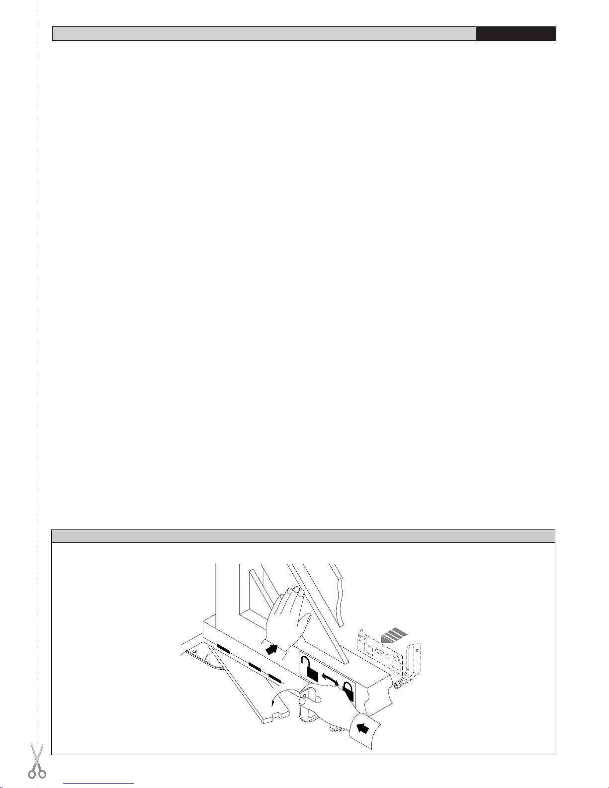
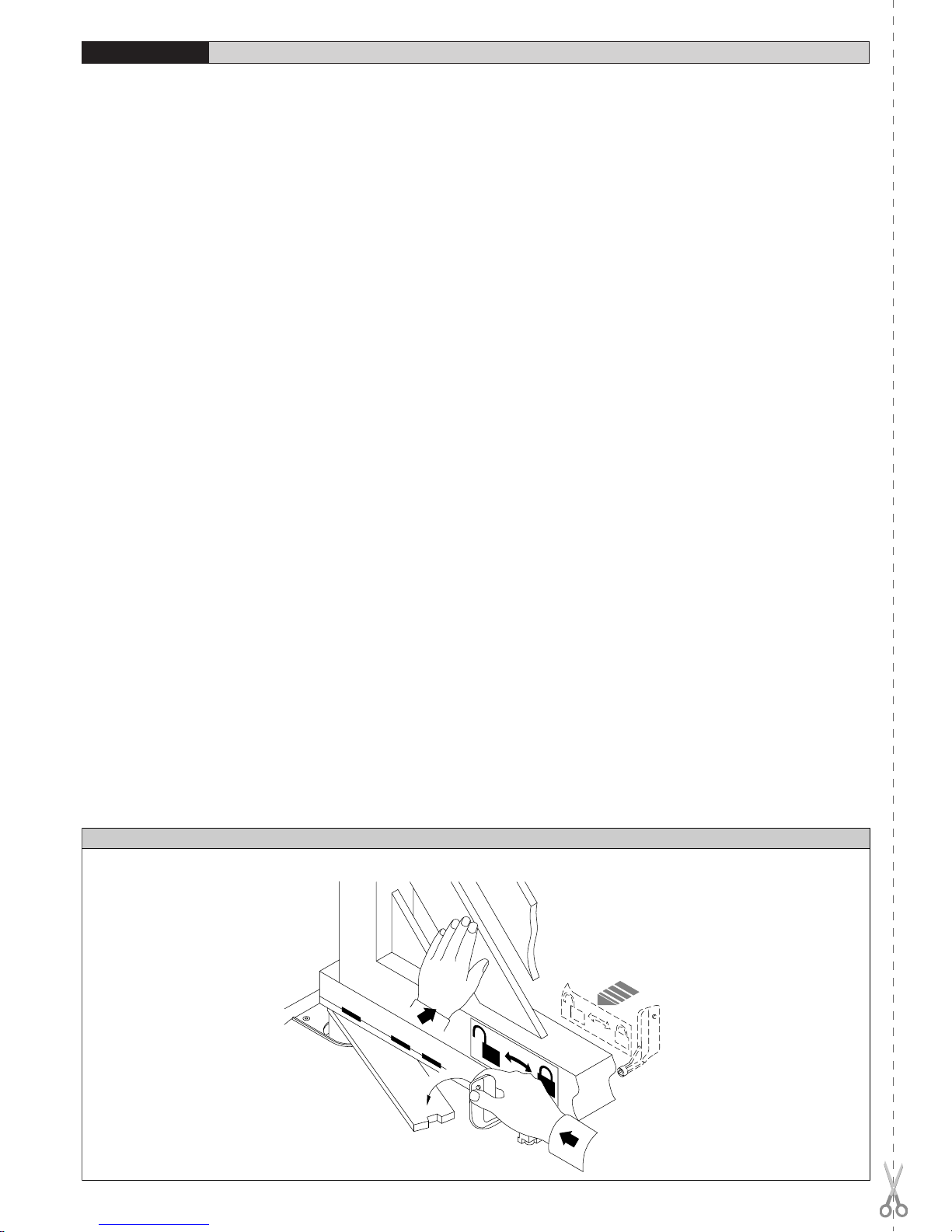
• Applicare all’anta le etichette di sblocco interne ed esterne, nel verso e
nella posizione indicata in fig.13. Il simbolo del lucchetto aperto, deve
essere sempre rivolto verso l’asse di rotazione dell’anta.
8) REGOLAZIONE FINECORSA
1- Posizionare i sensori sulle piastre come indicato nella fig. 10B. Colle-
gare i fine corsa di entrambi i motori alla centrale di comando e i cavi di
alimentazione del motore 2.
2- Portare elettricamente l’anta della motorizzazione 2 in apertura fino a
raggiungere la posizione massima desiderata.
3- Posizionare il sensore d’ apertura (rif.O) come in fig. 10A, rispettando
la misura minore di 3 mm dal magnete, fissandolo poi nella posizione
con le apposite viti.
4- Eseguire la stessa procedura portando l’anta in chiusura e posizionan-
do il sensore rif.C fig.10.
5- Collegare il motore 1 e ripetere la procedura di regolazione mantenen-
do collegato il motore 2.
6- Una volta eseguita la regolazione dei sensori di fine corsa dei due mo-
tori, effettuare alcune manovre verificando la posizione di fermo delle
ante ed eventualmente apportare le modifiche necessarie.
7- Procedere alla regolazione dei fermi d’arresto interni agendo sulle viti
(VRC - VRO) fig. 11. Questa operazione e’ necessaria nel caso in cui
non si utilizzino fermi d’arresto al suolo “FA” (fig.8 ).
8- Per consentire un’adeguata pressione in battuta dell’anta registrare la
vite VRO - VRC ( fig.11A, fig.11B).
9- Ultimata la regolazione, bloccare le viti VRO - VRC con le rispettivi viti
vt 4 x 12 (Fig.12).
10- E’ necessario fare le connessione del cavo del motoriduttore e dei fine
corsa in una scatola di derivazione posta all'esterno della cassa di fon-
dazione senza tagliare il cavo fornito in dotazione (fig.4).
11- Fig.11: inserire all'interno del foro filettato (A) della leva (B) l'ingrassa-
tore (C). Il grasso da noi consigliato è: ROCOL FOODLUBE MULTIPASTE.
9) REGOLAZIONE DELLA COPPIA MOTORE
ATTENZIONE! Il motore deve funzionare con un’alimentazione da 25V.
Laregolazionedicoppiadelmotore(antischiacciamento),vieneregolatanella
centralina di comando. Lo schema di collegamento del motore è riportata
nelle istruzioni d’uso della relativa centralina di comando.Vedere il manuale
istruzione della centralina di comando. La regolazione deve essere tarata
per la minima forza necessaria ad effettuare la corsa di apertura e chiusura
completa e comunque entro i limiti previsti dalle norme vigenti.
ATTENZIONE:Verificarecheilvaloredellaforzad’impattomisurato
nei punti previsti dalla norma EN12445, sia inferiore a quanto
indicato nella norma EN 12453.
ATTENZIONE! Una regolazione di coppia eccessiva, può compromettere
la sicurezza antischiacciamento. Al contrario, una regolazione di coppia
insufficiente, può non garantire una corsa di apertura o chiusura corretta.
MANUALE PER L’INSTALLAZIONE
ITALIANO

ELI 250 BT - Ver. 04 - 11
D811479_04
MANUALE PER L’INSTALLAZIONE ITALIANO
10) MANOVRA DI EMERGENZA
Lo sblocco di emergenza si effettua agendo, con l’apposita chiave in dota-
zione, sul gruppetto sblocco situato sotto il cancello sulla parte sporgente
della leva-perno. Per sbloccare, inserire la chiave nel triangolo di sblocco
e ruotare la chiave verso l’indicazione del lucchetto aperto per circa 90°
(Fig.13). Se l’anta è dotata di elettroserratura, sbloccare anche l’elettro-
serratura.Spingere manualmente l’anta per aprire/chiudere il cancello.Per
ripristinare l’operazione motorizzata, riposizionare il cancello allineato
con la leva che porta il gruppo blocco e girare la chiave verso l’indica-
zione del lucchetto chiuso (Fig.13) avendo cura di controllare l’avvenuto
aggancio dell’anta.Riporre la chiave di sblocco anta (e dell’elettroserratura
se presente) in luogo conosciuto agli utilizzatori.
11)VERIFICA DELL’AUTOMAZIONE
Prima di rendere definitivamente operativa l’automazione, controllare scru-
polosamente quanto segue:
• Verificare che tutti i componenti siano fissati saldamente.
• Controllare il corretto funzionamento di tutti i dispositivi di sicurezza
(fotocellule, coste sensibili, ecc.).
• Verificare il comando della manovra di emergenza.
• Verificare l’operazione di apertura e chiusura con i dispositivi di co-
mando applicati.
• Verificare la logica elettronica di funzionamento normale o personalizzata.
12) USO DELL’AUTOMAZIONE
Poichè l’automazione può essere comandata a distanza mediante radioco-
mando o pulsante di Start, e quindi non a vista, è indispensabile controllare
frequentemente la perfetta efficienza di tutti i dispositivi di sicurezza. Per
qualsiasi anomalia di funzionamento, intervenire rapidamente avvalendosi
dipersonalequalificato.Siraccomandadi tenere ibambiniadebita distanza
dal raggio di azione dell’automazione.
13) COMANDO
L’utilizzo dell’automazione consente l’apertura e la chiusura del cancello
in modo motorizzato.Il comando può essere di diverso tipo (manuale, con
radiocomando, controllo accessi con tessera magnetica, ecc.) secondo le
necessitàe lecaratteristichedell’installazione.Perivari sistemidicomando,
vedere le relative istruzioni. Gli utilizzatori dell’automazione devono essere
istruiti al comando e all’uso.
14) MANUTENZIONE
Per qualsiasi manutenzione, togliere l’alimentazione al sistema.
•
Verificare periodicamente il buono stato dei cardini ed il loro ingrassaggio.
• Ogni 2 anni applicare del grasso sul perno della cassa di fondazione
utilizzando l'apposito ingrassatore (C) presente nella leva (B) di Fig.11.
• Eseguire saltuariamente la pulizia delle ottiche della fotocellula.
• Farcontrollaredapersonalequalificato(installatore)lacorrettaregolazione
della frizione elettrica.
• Seil cavodi alimentazioneédanneggiato essodeveessere sostituitodal
costruttoreodalsuoservizioassistenzatecnicao comunquedapersona
con qualifica similare, in modo da prevenire ogni rischio.
• Perqualsiasianomaliadifunzionamentononrisolta,toglierealimentazione
al sistema e richiedere l’intervento a personale qualificato (installatore).
Nel periodo di fuori servizio, attivare lo sblocco manuale per consentire
l’apertura e la chiusura manuale.
15) RUMOROSITÀ
Il rumore aereo prodotto dal motoriduttore in condizioni normali di utilizzo è
costante e non supera i 70dB(A).
16) DEMOLIZIONE
L’eliminazione dei materiali va fatta rispettando le norme vigenti. Nel caso
di demolizione dell’automazione non esistono particolari pericoli o rischi
derivanti dall’automazione stessa.È opportuno in caso di recupero dei ma-
teriali, che vengano separati per tipologia (parti elettriche - rame - alluminio
- plastica - ecc.).
17) SMANTELLAMENTO
Nel caso l’automazione venga smontata per essere poi rimontata in
altro sito, bisogna:
• Togliere l’alimentazione e scollegare tutto l’impianto elettrico.
• Togliere il motoriduttore dalla base di fissaggio.
• Smontare il quadro di comando se separato e tutti i componenti del-
l’installazione.
• Nel caso alcuni componenti non possano essere rimossi o risultino
danneggiati, provvedere alla loro sostituzione.
18) MALFUNZIONAMENTO: CAUSE E RIMEDI
Perqualsiasianomaliadifunzionamentononrisolta,toglierel’alimentazione
al sistema e chiedere l’intervento di personale qualificato (installatore).
Nel periodo di fuori servizio, attivare lo sblocco manuale per consentire
l’aperturaelachiusuramanuale.Inquestoperiodo,permantenereilbloccoin
chiusura, provvedere a mantenerlo chiuso mediante catena e lucchetto.
18.1) Il cancello non apre. Il motore non gira
a) Verificarechefotocelluleocostesensibilinonsianosporcheoimpregnate,
o non allineate.Procedere di conseguenza.
b) Verificare chel’apparecchiatura elettronicasia regolarmente alimentata.
Verificare l’integrità dei fusibili.
c) Verificare il corretto funzionamento dei singoli dispositivi.
d) Se la centralina non funziona, sostituirla.
Nel caso le condizioni sopraelencate diano esito negativo, contattare un
centro assistenza autorizzato.
Se il cavo di alimentazione è danneggiato esso deve essere sostituito
dalcostruttoreodalsuoservizioassistenzatecnicaocomunquedauna
persona con qualifica similare, in modo da prevenire ogni rischio.
18.2) Il cancello non apre. L’attuatore vibra ma non avviene il movi-
mento.
a) Togliere e ridare l’alimentazione al sistema. Il primo comando di start
deve aprire. Nel caso l’attuatore vada in chiusura, invertire i rispettivi
collegamenti di marcia dell’attuatore.
b) Aiutare manualmente l’apertura dell’anta.Se l’anta apre, controllare se
ci sono problemi meccanici all’anta.
Nel caso le condizioni sopra elencate diano esito negativo, aumentare
la coppia nella centralina di comando ed eventualmente contattare un
centro assistenza autorizzato.
AVVERTENZE! Il buon funzionamento dell’attuatore è garantito solo
se vengono rispettati i dati riportati in questo manuale.
La ditta non risponde dei danni causati dall’inosservanza delle norme
di installazione e delle indicazioni riportate in questo manuale.
Le descrizioni e le illustrazioni del presente manuale non sono impe-
gnative.Lasciandoinalteratelecaratteristicheessenzialidelprodotto,
laDitta siriservadi apportare inqualunque momento lemodificheche
essaritieneconvenientipermiglioraretecnicamente-costruttivamente
e commercialmente il prodotto, senza impegnarsi ad aggiornare la
presente pubblicazione.

12 - ELI 250 BT - Ver. 04
D811479_04
Thank you for buying this product, our company is sure that you will be more
than satisfied with the performance of the product.This product is supplied
with a “Warnings” leaflet and an “Instruction manual”.These should both
be read carefully as they provide important information about safety, instal-
lation, operation and maintenance.This product complies with recognised
technical standards and safety regulations. We declare that this product
is in conformity with the following European Directives: 89/336/EEC and
73/23/EEC (and subsequent amendments).
WARNINGS:Anyassistancerequiredonautomationcomponentsmust
be carried out by a qualified technician (installer).
1) GENERAL OUTLINE
The ELI 250 BT electromechanical actuator is the ideal solution for under-
ground hinge-pivot installation. The actuator consists of a perfectly sealed
single-block reduction gear. The under hinge-pivot position maintains the
aesthetic appearance of the gate and practically hides the automation
system.
Once the bearing case is installed, the gate can be operated even without
fittingtheactuatorwhichcanbeinsertedlater.Whenmaintenanceisrequired,
this type of case allows the actuator to be taken out without removing the
gate leaf.The ELI 250 BT actuator can be fitted to any type of swing gate
which meets the values shown in the ”Technical Specifications”table.The
pushing force is set on the control unit (see specific manual).
The end-of-stroke operation is controlled by special end-of-stroke mag-
netic sensors and by mechanical stop blocks located inside the foundation
case.
CAUTION!Theactuatormod.ELI250BTisnotprovidedwithmechanical
torque adjustment.It is compulsory to use a control board of the same
manufacturer,according to the basic safety requirements of directives
73/23/CEE,89/336/CEE,98/37/CEE and provided with adequateelectric
torque adjustment.
2) GENERAL SAFETY
WARNING! An incorrect installation or improper use of the product
can cause damage to persons, animals or things.
• The “Warnings” leaflet and “Instruction booklet” supplied with this
product should be read carefully as they provide important information
about safety, installation, use and maintenance.
• Scrap packing materials (plastic, cardboard, polystyrene etc) according
to the provisions set out by current standards.Keep nylon or polystyrene
bags out of children’s reach.
• Keep the instructions together with the technical brochure for future
reference.
• This product was exclusively designed and manufactured for the use
specified in the present documentation. Any other use not specified in
this documentation could damage the product and be dangerous.
• The Company declines all responsibility for any consequences result-
ing from improper use of the product, or use which is different from that
expected and specified in the present documentation.
• Do not install the product in explosive atmosphere.
• Theconstructioncomponentsofthisproductmustcomplywiththefollowing
European Directives: 89/336/CEE, 73/23/EEC, 98/37/EEC and subse-
quent amendments.As for all non-EEC countries, the above-mentioned
standards as well as the current national standards should be respected
in order to achieve a good safety level.
• The Company declines all responsibility for any consequences resulting
from failure to observe GoodTechnical Practice when constructing clos-
ing structures (door, gates etc.), as well as from any deformation which
might occur during use.
• The installation must comply with the provisions set out by the following
EuropeanDirectives:89/336/CEE,73/23/EEC,98/37/EECandsubsequent
amendments.
• Disconnect the electrical power supply before carrying out any work on
the installation. Also disconnect any buffer batteries, if fitted.
• Fit an omnipolar or magnetothermal switch on the mains power supply,
having a contact opening distance equal to or greater than 3,5 mm.
• Check that a differential switch with a 0.03A threshold is fitted just before
the power supply mains.
• Check that earthing is carried out correctly: connect all metal parts for
closure (doors, gates etc.) and all system components provided with an
earth terminal.
• Fitallthesafetydevices(photocells,electricedgesetc.)whichareneeded
toprotectthe areafromanydangercausedbysquashing,conveyingand
shearing, according to and in compliance with the applicable directives
and technical standards.
• Position at least one luminous signal indication device (blinker) where it
can be easily seen, and fix a Warning sign to the structure.
• The Company declines all responsibility with respect to the automation
safety and correct operation when other manufacturers’components are
used.
• Only use original parts for any maintenance or repair operation.
• Do not modify the automation components, unless explicitly authorised
by the company.
• Instruct the product user about the control systems provided and the
manual opening operation in case of emergency.
• Do not allow persons or children to remain in the automation opera-
tion area.
• Keep radio control or other control devices out of children’s reach, in
order to avoid unintentional automation activation.
• Theusermustavoidanyattempttocarryoutworkorrepairontheautoma-
tion system, and always request the assistance of qualified personnel.
• Anything which is not expressly provided for in the present instructions,
is not allowed.
• Installation must be carried out using the safety devices and controls
prescribed by the EN 12978 Standard.
3) MAIN AUTOMATION PARTS
Sealed mechanical actuator (fig.1) including:
a) 24V permanent magnet motor.
b) Double worm-screw reduction gear with output gear in special alu-
minium alloy.
c) Exit lever, end-of-stroke sensors and mechanical stop blocks.
d) Bearing foundation case (ready for automation).
e) Series of levers for gate movement.
f) Release unit with key.
CAUTION! The actuator can be fitted either on the left or on the right,
which are conventionally defined by looking at the gate from the inside
(opening direction).
4) TECHNICAL SPECIFICATIONS
Power supply................................................................................24V (*)
Motor revolutions................................................................................. 2100
Output shaft revolutions................................................................1,45 min-1
Absorbed power .................................................................................175W
Absorbed current....................................................................... 10,1 A max
Leafrotationspeed :................from8°/sec.(15sec./120°)to 4°/sec.(30sec./120°)
Max torque.......................................................................................350 Nm
Max leaf length/weight...............................................2.5m/4000N (~400kg)
3.5m/2500N (~250kg)
Max. leaf opening .................................................................................120°
Blocking function ..................................Irreversible gearmotor; electric lock
necessary for leaves longer than 2,5m
Impact reaction...................................Electronic clutch (with control panel)
Manual manoeuvre...................................................................Release key
Max. no.manoeuvres in 24 hours.......................................................... 100
Environmental conditions ............................................from -20°C to +50°C
Lubrication......................................................................Permanent grease
Degree of protection.......................................................................IP67 AM
Actuator weight......................................................................100N (~ 10kg)
Overall dimensions........................................................................See fig.3
(*) Special voltages on request.
5) ACTUATOR INSTALLATION
5.1) Preliminary checks
Check that:
• The upper hinge is in good condition and possibly adjustable.
• A hole can be dug for burying the case under the hinge.
• The ”FA” stop plates of the leaves are installed (fig.8).
• Repairorreplacethefaultyorwornpartsofthestructurestobesubjected
to movement.
An exploded view of the installation is shown in fig.1.
The automation reliability and safety are directly influenced by the
state of the gate structure.
5.2)The main automation components are (Fig.2):
I) Type-approvedadequatelyratedomnipolarcircuitbreakerwithatleast
3,5 mm contact opening, provided with protection against overloads
and short circuits, suitable for cutting out automation from the mains.
Place,ifnot already installed, atype-approveddifferentialswitchwith
a 0.03A threshold just before the automation system.
INSTALLATION MANUAL
ENGLISH

ELI 250 BT - Ver. 04 - 13
D811479_04
Qr) Control panel and built-in receiver.
S) Key selector.
AL) Blinker with tuned antenna.
M) Actuator.
E) Electric lock (compulsory for leaves longer than 2,5m).
Fte) Pair of external photocells (transmitter section).
Fre) Pair of external photocells (receiver section).
Fti) Pair of internal photocells with CF posts (transmitter section).
Fri) Pair of internal photocells with CF posts (receiver section).
T) 1-2-4 channel transmitter.
RG58)
Cable for antenna.
D) Connector block.
5.3) Electrical installation set-up
Lay out the electrical installation as shown in fig.2, with reference to the CEI
64-8 and IEC 364 provisions, complying with the HD 384 and other national
standardsin forceforelectricalinstallation.Themainspowersupply connec-
tionsmustbe kepttotally separate from theservice connections (photocells,
electric edges, control devices etc.).
WARNING! It is recommended to use the following cables:
• Connection to the mains: multipolar cable with minimum cross sec-
tion of 3x1.5 sq mm.
• Connection to the control unit:
- Operator farthest from the control unit (Fig.2)
for the motor: 2x2.5 sq mm cables;
for the limit switch sensors: 3x1 sq mm cables.
- Operator nearest to the control unit (Fig.2)
for the motor: 2x1.5 sq mm cables;
for the limit switch sensors: 3x1 sq mm cables.
Always use the cables prescribed by current standards.
For example, if the cable is out side (in the open), it has to be at least
equal to H07RN-F, but if it is on the inside (or outside but placed in
a plastic cable cannel) it has to be or at least egual to H05VV-F with
section 3x1.5mm2.
Connect the control and safety devices in compliance with the previously
mentioned electrical installation standards.Fig.2 shows the number of con-
nections and the cross section for cables having a length of approximately
100 metres; in case of longer cables, calculate the cross section for the
actual automation load.
Warning!Foractuatorwiringandaccessoryconnection,refertotherelevant
instruction manuals.The control panels and accessories must be suitable
for use and conform to current standards.
5.4) Foundation case cementing
The foundation case must be cemented under the hinge pivot, taking into
consideration that the actuator bearing shaft must be perfectly aligned with
the leaf rotation axis.If the gate has fixed hinges, remove the gate and the
lower hinge. If the leaf is sufficiently separated from the ground and cannot
be removed, proceed to supporting it by means of a shim placed between
the ground and the leaf during installation.If the gate has adjustable hinges,
remove the lower one, slacken the upper hinge and move the leaf to the
side. If the gate has been recently installed, fit an upper adjustable hinge.
Dig a foundation hole having the dimensions specified in fig.4.Lay an drain
pipe (fig.4) for rainwater in order to prevent it from being collected inside the
foundationcase.Layaracewayforthe powersupply cable as farasconnec-
tor block “D”.Lay a solid foundation (fig.3) at the bottom, where to bury the
foundation box.To obtain good squareness between cases and leaves, set
outtheiralignmentusingastretchedrope between the 2 bearing pivots,and
aligning the 2 reference points “C” with each other (see fig.14).
Let the cement harden for the time needed.
6) GATE LEAF FITTING
• Abundantly grease the pivot in the foundation case.
• Position the lever assembly by inserting pipe “A” into the pivot of the
foundation case, as in fig.9. If the height of the assembled levers is not
sufficient, insert shim“S”between the assembled lever unit and the gate
leaf, as in fig.5.
• Place the gate leaves in the closing and in the closed position against
the centre stop plate.
• Perfectly align the assembled lever unit to the hinge.
• If a shim is used, weld it to the leaf first and then weld the lever unit
to the shim.
• Check the leaf operation.
• If the gearmotor is not to be installed, fit the foundation case cover and
fix with suitable screws.
At this stage, the gate opens and closes manually. All that remains to be
done is to position the gearmotor.
7) GEARMOTOR FITTING
Remove the nuts from the bottom of the case using a CH19 socket wrench.
•
Fitthe end-of-strokesensors andmechanicalsmall blocksontotheplates
(Fig. 6A).
•
TightentheVRscrewsandthecorrespondingVT4x12screwsandselect
left-hand or right-hand fixing position (Fig.6A).
Plate sides are marked as follows: R- RIGHT SIDE
L - LEFT SIDE
• Secure the plate on the gearmotor by means of the four M8 screws as
shown in Fig.6B. After mounting the gearmotor on the foundation case,
connect the control unit in order to be able to move the output lever and
then tighten the other two M8 screws (Fig.9).
• Securethemagnet ontotheplateasshowninFig.7.Theninstalltheplate
assembly onto the gearmotor outlet shaft and determine the diagonal
position of the holes (R-L) for right or left fastening (Fig.7).
• Secure the gearmotor to the foundation case in the position indicated in
Fig. 9 using the 4 nuts previously removed.
• Pass the cables of the end-of-stroke sensors so that they do not touch
the moving parts (Fig.9).
• Pass the cables of the end-of-stroke sensors so that they do not touch
the moving parts (Fig.9).
• Fit the motor-pivot connecting lever components following the correct
sequence given in fig.8 and fig.9.
Inthecasewherethepositionoftheleversinterfereswiththeassemblyof
the components, supply the motors with current (by means of the control
unit) until the levers reach the required position.
• Grease the hub into which pipe A will be inserted and the hubs of lever
B (Fig.9).
• Check the opening and closing operations.
• Attach to the leaf the internal and external release labels observing the
direction and position indicated in fig.13.The open-padlock symbol must
always be directed towards the leaf rotation axis.
8) END-OF-STROKE ADJUSTMENT
1- Position the sensors on the plates as indicated in fig. 10B.Connect the
limit switches of both motors and the cables supplying power to motor
2 to the control unit.
2- Electrically open the leaf of motor drive 2 until it reaches the maximum
opening position required.
3- Position the opening sensor (ref.O) as in fig. 10A, keeping to the mea-
surement of less than 3 mm from the magnet, then fix it in place by
means of the appropriate screws.
4- Carry out the same procedure to move the leaf to its closing position,
and fit the sensor with ref.C in fig. 10.
5- Connect motor 1 and repeat the adjusting procedure while keeping mo-
tor 2 connected.
6- Having adjusted the limit switch sensors of the two motors, carry out a
few manoeuvres to check the stopping position of the leaves, and make
any necessary modifications.
7- Proceed to adjust the internal backstops by turning the screws (VRC
-VRO) in fig.11.This operation is required in the case where there are
no “FA” backstops fitted to the ground (fig. 8 ).
8- To provide adequate pressure of the leaf against the end stop, regulate
screwsVRO -VRC ( fig. 11A, fig. 11B).
9- Once the adjustment has been completed, secure screws VRO - VRC
by means of respective screws vt 4 x 12 (Fig.12).
10- Connections of the gearmotor cable and the limit switches must be car-
ried out in a junction box positioned outside the foundation case without
cutting the cable supplied as standard (Fig.4).
11- Fig.11:insert the greaser (C) into the threaded hole (A) of the lever (B).
The type of grease recommended is: ROCOL FOODLUBE MULTIPASTE.
9) MOTORTORQUE SETTING
CAUTION!
The power supply for the motor must be rated at 25V.
WhenusingtheARIESmod.controlunitwiththetorquesetto“F4”(maximum
torque), it is compulsory to fit the ground stop plates “FA” both on opening
and closing.
Themotor torque(antisquash)settingtakesplaceinthecontrolunit.See the
control unit instruction manual.The wiring diagram of the motor is included
in the instructions for use for the relative control unit.This setting must be
calibrated according to the minimum force needed to carry out the complete
opening and closing strokes, and always within the limits provided for by
current standards.
INSTALLATION MANUAL ENGLISH

14 - ELI 250 BT - Ver. 04
D811479_04
INSTALLATION MANUAL
ENGLISH
WARNING: Check that the impact force value measured at the
points established by the EN 12445 standard is lower than that
specified in the EN 12453 standard.
CAUTION! Excessive torque setting can jeopardise antisquash safety. On
the contrary, insufficient torque setting may not guarantee a correct opening
or closing stroke.
10) EMERGENCY MANOEUVRE
Emergency release is obtained by using the key provided, on the release
unit which is located under the gate, on the protruding section of the lever-
pivot.To release, insert the key in the release triangle and turn it by about
90° in the direction shown by the open-padlock symbol (fig.13).If the leaf is
equipped with an electric lock, release the electric lock as well.
To open/close the gate, push it manually.To restoremotor-driven operation,
reposition the gate by aligning it with the lever bearing the lock unit, and turn
thekeyin thedirectionshownbytheclosed-padlocksymbol(fig.13)checking
thatengagement is correctlyrestored. Keep the leaf release key (and that of
the electric lock, if any) in a place which is known to the users.
11) AUTOMATION CHECK
Before making the automation fully operational, carefully carry out the fol-
lowing procedure:
• Check that all components are tightly fixed.
• Check the correct operation of all safety devices (photocells, electric
edges etc.).
• Check the emergency manoeuvre command.
• Check the opening and closing operations with the control devices provided.
• Check the standard or customised electronic function logic.
12) AUTOMATION OPERATION
Sincetheautomationsystemcanberemotelycontrolled bymeansof aradio
control device or a Start button, and therefore out of sight, all safety devices
must be frequently checked in order to ensure their perfect efficiency. In
the event of any anomalous operation, request immediate assistance from
qualified personnel.
Children must be kept at a safe distance from the automation operation
area.
13) CONTROL
The automation system allows motor-driven gate opening and closing
operations to be carried out.Various types of control are provided (manual,
radio control, magnetic card access control etc.) depending on the installa-
tion requirements and characteristics. See the specific instructions for the
various control systems.All automation system users must be instructed on
automation control and operation.
14) MAINTENANCE
Before carrying out any maintenance to the installation, disconnect the
mains power supply.
• Periodically check that hinge-pivots are in good condition and
properly greased.
• Grease the pin on the foundation case every two years, using the appro-
priate greaser (C) located on the lever (B) as shown in Fig.11.
• Occasionally clean the photocell optical components.
• Have a qualified technician (installer) check the correct setting of the
electric clutch.
• If the power supply cable is damaged, it must be replaced by the manu-
facturer or its technical assistance service, or else by a suitably qualified
person, in order to prevent any risk.
• Whenanyoperationalmalfunction isfound,andnotresolved,disconnect
themainspowersupplyandrequesttheassistanceofaqualifiedtechnician
(installer).When automation is out of order, activate the manual release
to allow the opening and closing operations to be carried out manually.
15) NOISE
The aerial noise produced by the gearmotor under normal operating condi-
tions is constant and does not exceed 70dB(A).
16) SCRAPPING
Materials must be disposed of in conformity with the current regulations.
In case of scrapping, the automation devices do not entail any particular
risks or danger. In case of recovered materials, these should be sorted out
by type (electrical components, copper, aluminium, plastic etc.).
17) DISMANTLING
Whentheautomationsystemisdisassembledtobereassembledonanother
site, proceed as follows:
• Disconnect the power supply and the entire electrical installation.
• Remove the gearmotor from its fixing base.
•
Disassemble the control panel, if separate, and all installation components.
• In the case where some of the components cannot be removed or are
damaged, they must be replaced.
18) MALFUNCTION: CAUSES AND REMEDIES
When any operational malfunction is found,and not resolved, discon-
nect the mains power supply and request the assistance of a qualified
technician (installer).
When automation is out of order, activate the manual release to allow the
opening and closing operations to be carried out manually.
During this period of time, keep the lock in the closed position by means
of a chain and padlock.
18.1) The gate does not open.The motor does not turn.
a) Checkthatthephotocellsorelectric edges are not dirty, or impregnated,
or misaligned. Proceed accordingly.
b) Check that the electronic appliance is correctly supplied. Check the
integrity of the fuses.
c) Check that the individual devices operate correctly.
d) If the control unit does not work, it must be replaced.
In the case where the above-mentioned checks give no results, contact
an authorised customer service centre.
Ifthesupplycableisdamaged,itmustbereplacedbythemanufacturer,
byitstechnical service centeror,inanycase,bya qualifiedtechnician
so as to avoid any risk.
18.2) The gate does not open. The actuator vibrates but there is no
movement.
a) Disconnect and reconnect the mains power supply.The first Start com-
mand must open. Should the actuator move to the closing function,
reverse the respective running connections.
b) Manuallyhelptheleafopeningoperation.Iftheleafopens,checkwhether
there are any mechanical problems.In the case where the above-men-
tionedchecksgivenoresults,increase thetorqueinthecontrol unitand,
if necessary, contact a qualified technician.
WARNINGS.Correctoperationoftheactuatorisonlyguaranteedwhen
the data specified in this manual are respected.
The company cannot be held responsible for any damage caused by
failure to observe the installation standards and directives specified
in the present manual.
Thedescriptionsandillustrationscontainedinthepresentmanualare
not binding.The Company reserves the right to make any alterations
deemed appropriate for the technical,manufacturing and commercial
improvement of the product, while leaving the essential product fea-
tures unchanged, at any time and without undertaking to update the
present publication.

ELI 250 BT - Ver. 04 - 15
D811479_04
MANUEL D’INSTALLATION FRANÇAIS
Nous vous remercions pour avoir choisi ce produit.Nous sommes certains
qu’ilvousassureralesperformancesquevoussouhaitez.Lisezattentivement
la brochure “Avertissements” et le “Manuel d’instructions” qui accompa-
gnentceproduit,puisqu’ilsfournissentd’importantesindicationsconcernant
la sécurité, l’installation, l’utilisation et l’entretien. Ce produit est conforme
aux règles reconnues de la technique et aux dispositions de sécurité.Nous
certifions sa conformité avec les directives européennes suivantes: 86/336/
CEE, 73/23/CEE (et modifications successives).
AVERTISSEMENTS:Touteintervention sur lescomposants de lamoto-
risation doit être effectuée par du personnel qualifié (installateur).
1) GÉNÉRALITÉS
Le vérin électromécanique ELI 250 BT est la solution idéale pour des appli-
cationsenterrées sousles gonds.Levérinestréaliséavecun seulréducteur
monobloc étanche. La caisse de fondation sous les gonds ne compromet
pas l’esthétique du portail et rend la motorisation pratiquement invisible.
Après avoir installé la caisse porteuse, le portail peut être actionné même
sans monter le vérin. Celui-ci peut être monté par la suite.
En cas d’entretien, ce type de caisse permet d’enlever le vérin sans avoir
à démonter le vantail du portail.Le vérin ELI 250 BT peut être appliqué sur
n’importe quel type de portail battant conforme aux valeurs indiquées dans
le tableau des Caractéristiques techniques. La force de poussée se règle
sur la centrale de commande (voir manuel spécifique).
Lefonctionnementenfindecourseestrégulépardescapteursmagnétiques
de fin de course et des butées mécaniques situés à l’intérieur de la caisse
de fondation.
ATTENTION: L’actionneur mod.ELI 250 BT n’est pas doté d’un réglage
mécaniquedecouple.Ilestobligatoired’utiliseruntableaudecommande
du même constructeur, conformément aux exigences essentielles de
sécurité des directives 73/23/CEE,89/336/CEE,89/37/CEE et doté d’un
réglage électrique du couple adéquat.
2) SECURITE GENERALE
ATTENTION! Une installation erronée ou une utilisation impropre du
produit peuvent provoquer des lésions aux personnes et aux ani-
maux ou des dommages aux choses.
• Lisez attentivement la brochure “Avertissements” et le “Manuel d’ins-
tructions” qui accompagnent ce produit, puisqu’ils fournissent d’im-
portantes indications concernant la sécurité, l’installation, l’utilisation et
l’entretien.
• Eliminer les matériaux d’emballage (plastique, carton, polystyrène etc.)
selon les prescriptions des normes en vigueur.Ne pas laisser des enve-
loppes en nylon et polystyrène à la portée des enfants.
• Conserver les instructions et les annexer à la fiche technique pour les
consulter à tout moment.
• Ceproduit a étéconçuet réaliséexclusivementpourl’utilisation indiquée
dans cette documentation. Des utilisations non indiquées dans cette
documentationpourraientprovoquerdes dommages au produitetrepré-
senter une source de danger pour l’utilisateur.
• LaSociétédéclinetoute responsabilitédérivéed’uneutilisationimpropre
oudifférentedecelle àlaquelle leproduitaétédestinéetquiestindiquée
dans cette documentation.
• Ne pas installer le produit dans une atmosphère explosive.
• Les éléments constituant la machine doivent être conformes aux Di-
rectives Européennes suivantes: 89/336/CEE, 73/23/CEE, 98/37 CEE
et modifications successives. Pour tous les Pays en dehors du Marché
Commun, outre aux normes nationales en vigueur il est conseillé de
respecter également les normes indiquées cihaut afin d’assurer un bon
niveau de sécurité.
• LaSociétédéclinetouteresponsabilité en cas de non respect des règles
de bonne technique dans la construction des fermetures (portes, por-
tails etc.), ainsi qu’en cas de déformations pouvant se produire pendant
l’utilisation.
• L’installation doit être conforme aux prescriptions des Directives Euro-
péennes:89/336/CEE, 73/23/CEE, 98/37 CEE et modifications succes-
sives.
• Couper l’alimentation électrique avant d’effectuer n’importe quelle inter-
vention sur l’installation. Débrancher aussi les éventuelles batteries de
secours.
• Prévoirsurlaligned’alimentationdelamotorisationuninterrupteurouun
magnétothermique omnipolaire avec distance d’ouverture des contacts
égale ou supérieure à 3,5 mm.
• Vérifier qu’en amont de la ligne d’alimentation il y a un interrupteur dif-
férentiel avec seuil de 0,03A.
• Vérifier si l’installation de terre est effectuée correctement: connecter
toutes les parties métalliques de la fermeture (portes, portails etc.) et
tous les composants de l’installation dotés de borne de terre.
• Appliquertouslesdispositifsdesécurité(cellulesphotoélectriques,barres
palpeusesetc.)nécessairesàprotégerlazonedesdangersd’écrasement,
d’entraînement, de cisaillement, selon et conformément aux directives
et aux normes techniques applicables.
• Appliqueraumoinsundispositifdesignalisationlumineuse(feuclignotant)
en position visible, fixer à la structure un panneau de Attention.
• La Société décline toute responsabilité en matière de sécurité et de bon
fonctionnementdelamotorisationsidescomposantsd’autresproducteurs
sont utilisés.
• Utiliserexclusivementdespiècesoriginalespourn’importequelentretien
ou réparation.
• Ne pas effectuer des modifications aux composants de la motorisation
si non expressément autorisées par la Société.
• Informer l’utilisateur de l’installation sur les systèmes de commande
appliqués et sur l’exécution de l’ouverture manuelle en cas d’urgence.
• Ne pas permettre à des personnes et à des enfants de stationner dans
la zone d’action de la motorisation.
• Nepaslaisserdesradiocommandesoud’autresdispositifsdecommande
à portée des enfants afin d’éviter des actionnements involontaires de la
motorisation.
• L’utilisateur doit éviter toute tentative d’intervention ou de réparation de
la motorisation et ne doit s’adresser qu’à du personnel qualifié.
• Tout ce qui n’est pas expressément prévu dans ces instructions,
est interdit.
• L’installation doit être faite en utilisant des dispositifs de sécurité et des
commandes conformes à la norme EN 12978.
3) PARTIES PRINCIPALES DE LA MOTORISATION
Vérin mécanique étanche (fig.1) constitué de:
a) Moteur à aimants permanents 24V
b) Réducteur à double vis sans fin avec engrenage de sortie en alliage
spécial alu.
c) b) Levier sortie, capteurs de fin de course et butées mécaniques.
d) Caisse de fondation porteuse (prédispose à la motorisation).
e) Série de leviers pour le mouvement du portail.
f) Groupe de déblocage avec clé.
ATTENTION: Le vérin peut être monté tant à droite qu’à gauche. Par con-
vention l’on observe le portail du côté interne (direction d’ouverture).
4) CARACTÉRISTIQUESTECHNIQUES
Alimentation..................................................................................24V (*)
Tours du moteur................................................................................... 2100
Tours de l’arbre de sortie............................................................. 1,45 min-1
Puissance absorbée...........................................................................175W
Courant absorbé........................................................................10.1 A max
Vitesse de rotation de la porte:..de 8°/sec.(15 sec./120°) à 4°/sec.(30 sec./120°)
Couple maxi.....................................................................................350 Nm
Longueur/poids maxi du vantail..............................2.5 m/4000N (~400 Kg)
...................................................................................3.5m/2500N (~250kg)
ELI 250 BTV 2m/1500N (~150kg)
Ouverture maxi du vantail.....................................................................120°
Blocage en fermeture........................................Motoréducteur irréversible;
électroserrure obligatoire pour vantaux de plus de 2.5m de long
Réaction au choc....embrayage électronique (avec tableau de commande)
Manoeuvre manuelle........................................................ clé de déblocage
N° maxi de manoeuvres en 24 heures.................................................. 100
Conditions ambiantes...........................................................-20°C à +50°C
Lubrification.................................................................Graisse permanente
Degré de protection........................................................................IP67 AM
Poids du vérin........................................................................100N (~ 10kg)
Dimensions hors-tout......................................................................Voir fig.3
(*) Tensions spéciales d’alimentation sur demande.
5) INSTALLATION DUVÉRIN
5.1)Vérifications préliminaires
Contrôler:
•
Que la charnière supérieure est en bon état et si possible de type réglable.
• Qu’il est possible d’effectuer le trou pour enterrer la caisse sous
les gonds.
• Que les butées d’arrêt ”FA” des vantaux sont installées (fig.8).
• Réparer ou remplacer les parties défectueuses ou usées des structures
en mouvement.
La fig.1 est une vue éclatée de l’installation.
Lafiabilitéetlasécuritédelamotorisationsontdirectementinfluencées
par l’état de la structure du portail.

16 - ELI 250 BT - Ver. 04
D811479_04
MANUEL D’INSTALLATION
FRANÇAIS
5.2) Composants principaux de la motorisation (Fig.2):
I) Interrupteur omnipolaire homologué de portée adéquate avec ouver-
ture des contacts d’au moins 3,5 mm, doté de protection contre les
surcharges et les courts-circuits, en mesure de couper la motorisation
de la ligne.
Prévoir en a mont de la motorisation un interrupteur différentiel homo-
logué avec seuil de 0,03A.
Qr) Unité de commande et récepteur incorporé.
S) Sélecteur à clé.
AL) Feu clignotant avec antenne accordée.
M) Vérin.
E) Serrure électrique (obligatoire pour des vantaux de plus de 2.5m de
long).
Fte) Couple de cellules photoélectriques externes (partie émettrice).
Fre) Couple de cellules photoélectriques externes (partie réceptrice).
Fti) Couple de cellules photoélectriques internes avec colonnettes CF
(partie émettrice).
Fri) Couple de cellules photoélectriques internes avec colonnettes CF
(partie réceptrice).
T) Émetteur 1-2-4 canaux.
RG58)
Câble pour antenne.
D) Boîte de dérivation.
5.3) Prédisposition installation électrique
Prédisposer l’installation électrique comme indiqué à la fig. 2 se référant
aux normes en vigueur pour les installations électriques CEI 64-8, IEC364,
harmonisation HD384etautres normesnationales.Tenirnettementséparées
les connexions de l’alimentation de ligne des connexions de service (cellules
photoélectriques, barres palpeuses, dispositifs de commandes etc.).
ATTENTION! Utiliser les câbles suivants:
• Branchementauréseau:câblemultibrinàla sectionminimumde3x1,5
mm2.
• Branchement à l’unité de commande:
- Actionneur le plus loin de l’unité de commande (Fig.2)
pour le moteur: câbles de 2x2,5 mm2;
pour les capteurs de fin de course: câbles de 3x1 mm2.
- Actionneur le plus près de l’unité de commande (Fig.2)
pour le moteur: câbles de 2x1,5 mm2;
pour les capteurs de fin de course: câbles de 3x1 mm2.
Toujours utiliser les câbles prévus par les réglementations en vigueur.
A titre d’exemple, si le cable est à l’exterieur (exposé aux intempéries),
il doit au moins être égal à H07RN-F tandis que, si à l’interieur ou bien à
l’exterieur dans un canal de protection, il doit au moins être égal à H05
VV-F avec 3x1.5mm2de section.
Réaliser les connexions des dispositifs de commande et de sécurité confor-
mément aux normes pour les installations précédemment indiquées.Lafig.2
illustrelenombredeconnexionsetlasectionpourunelongueurdesconducteurs
d’environ 100 mètres; pour des longueurs supérieures, calculer la section pour
la charge réelle de la motorisation.
Attention! Pour le câblage de l’actionneur et la connexion des accessoires,
consulter les manuels d’instructions correspondants. Les centrales de com-
mande et les accessoires doivent être indiqués pour l’utilisation et conformes
aux normes en vigueur.
5.4) Cimentation de la caisse de fondation
Lacaissedoitêtrecimentéesouslesgondsentenantcomptequel’arbreporteur
du vérin doit être parfaitement aligné avec l’axe de rotation du vantail.
Si le portail est du type à charnières fixes, il faut enlever le portail et la char-
nière inférieure. Si le vantail est suffisamment haut par rapport au sol et ne
peut pas être enlevé, il faudra le soutenir avec une cale placée entre le sol et
le vantail pendant la mise en oeuvre.
Si le portail est du type à charnières réglables, il faudra enlever celle
inférieure, desserrerla charnièresupérieure etdéplacer latéralement
le vantail. Si le portail est neuf, prévoir une charnière supérieure de type
réglable. Effectuer un trou de fondation ayant les dimensions indiquées à la
fig.4. Prévoir un tube d’écoulement (fig.4) pour l’eau de pluie, de telle façon
à éviter la stagnation de l’eau à l’intérieur de la caisse de fondation. Prédis-
poser une conduite à câbles pour le câble d’alimentation jusqu’à la boîte de
dérivation ”D” située à proximité.
Réaliser sur le fond une fondation solide (fig.3) pour y noyer le cais-
son de fondation. Pour obtenir une bonne orthogonalité entre les caisses
et les vantaux, il faut en marquer l’alignement avec une corde tendue entre
les 2 pivots porteurs, en alignant entre elles les 2 références “C”(voir fig.14).
Laisser le ciment se durcir autant que nécessaire.
6) MONTAGE DUVANTAIL
• Bien graisser le pivot situé dans la caisse de fondation.
• Positionner le groupe leviers en introduisant le tube A dans le pivot de la
caisse de fondation comme indiqué à la fig.9. Si la hauteur des leviers
montésn’estpassuffisante,prévoirunecale“S”àinterposerentrelegroupe
des leviers montés et le vantail du portail comme indiqué à la fig.5.
• Positionner les vantaux en fermeture et en butée dans l’arrêt central.
• Aligner parfaitement le groupe des leviers montés au gond.
• Sionutiliseunecale,lasouderd’abordauvantail,puissouderlegroupe
des leviers à la cale.
• Vérifier le fonctionnement du vantail.
• Si on ne monte pas le motoréducteur, monter le couvercle de la caisse
de fondation et le fixer avec les vis spéciales.
À ce point le portail s’ouvre et se ferme manuellement. Il reste à posi-
tionner le motoréducteur.
7) MONTAGE DU MOTORÉDUCTEUR
Enlever les écrous du fond de la caisse avec une clé CH19.
•
Monter les capteurs de fin de course et les butées mécaniques sur les
plaques (Fig. 6A).
• Visser les visVR et les vis correspondantesVT 4 x 12 et individualiser
la position de fixation à droite ou à gauche (Fig.6A).
Côté plaque marqué: R- COTE DROIT
L - COTE DROIT.
•
Fixer la plaque sur le motoréducteur en utilisant les 4 vis M8 indiquées
dans la Fig. 6B. Après avoir monté le motoréducteur sur la caisse de
fondation, brancher l’unité de commande pour pouvoir déplacer le levier
de sortie et ensuite fixer les deux autres vis M8 (Fig.9).
•
Fixer l’aimant sur la plaque comme indiqué dans le dessin de la Fig.7.
Monterensuitel’ensembleplaquesurl’arbredesortiedumotoréducteur
et individualiser la position en diagonale des trous (R-L) pour la fixation
à droite ou à gauche (Fig.7).
•
Lemotoréducteursefixeàlacaissedefondationdanslapositionindiquée
dans la Fig. 9 en utilisant les 4 écrous enlevés précédemment.
•
Faire passer les câbles des capteurs de fin de course de façon à ce qu’ils
aillent toucher les pièces en mouvement (Fig.9).
•
Pourobtenirunerotationdanslesensdesaiguillesd’unemontre,brancher
lesfilsdumoteur comme indiqué dans laFig.15.Inverserle branchement
pour le sens contraire des aiguilles d’une montre.
• Monter les pièces du levier de connexion moteur-pivot dans l’exacte
séquence indiquée dans la fig.8 et fig.9. Si la position prise par les
leviers entrave le montage des pièces, appliquer l’alimentation aux
moteurs (par l’unité de commande) jusqu’à ce que les leviers prennent
la position voulue.
• GraisserlemoyeudanslequelletubeAserapasséainsiquelesmoyeux
du levier B (Fig.9).
• Vérifier l’opération d’ouverture et de fermeture.
• Appliquerauvantaillesétiquettesdedéblocageinternesetexternes,
dans le sens et dans la position indiquué à la fig.13.
Le symbole du cadenas ouvert doit être toujours dirigé vers l’axe de
rotation du vantail.
8) RÉGLAGE FIN DE COURSE
1- Monter les détecteurs sur les plaques comme indiqué dans la figure
10B.Brancher les fins de course des deux moteurs et les câbles d’ali-
mentation du moteur 2 à l’unité de commande.
2- Actionner électriquement la porte de la motorisation 2 en ouverture
jusqu’à atteindre la position maximum désirée.
3- Installer le détecteur d’ouverture (réf.O) comme indiqué dans la figure
10A,enrespectantladistanceminimumde3mmàpartirdel’aimant,en
le fixant ensuite dans cette position avec les vis prévues à cet effet.
4- Réaliser la même procédure en actionnant la porte en fermeture et en
positionnant le détecteur réf.C figure 10.
5- Brancher le moteur 1 et répéter la procédure de réglage en maintenant
le moteur 2 branché.
6- Après avoir réalisé le réglage des détecteurs de fin de course des deux
moteurs,effectuerplusieursmanœuvresenvérifiantlapositiondebutée
des portes et apporter éventuellement les modifications nécessaires.
7- Procéder au réglage des butées d’arrêt internes en jouant sur les vis
(VRC - VRO) figure 11. Cette opération est nécessaire au cas où les
butées d’arrêt au sol ne seraient pas utilisées “FA” (figure 8).
8- Régler la vis VRO - VRC pour permettre une pression adéquate en
butée de la porte (figure 11A, figure 11B).
9- Après avoir terminé le réglage, bloquer les vis VRO - VRC avec les vis
correspondantes vt 4 x 12 (Fig.12).

ELI 250 BT - Ver. 04 - 17
D811479_04
MANUEL D’INSTALLATION FRANÇAIS
10-Il faut réaliser les branchements du câble du motoréducteur et des fins
de course dans un boîtier de dérivation placé à l’extérieur du caisson de
fondation sans couper le câble fourni (Fig.4).
11-Fig.11:insérer à l’intérieur du trou fileté (A) du levier (B) le graisseur (C).
Nous conseillons d’utiliser la graisse:ROCOL FOODLUBE MULTIPASTE.
9) RÉGLAGE DU COUPLE MOTEUR
ATTENTION: Le moteur doit fonctionner avec une alimentation de 25 V.
Le réglage de couple du moteur (anti-écrasement) se fait dans l’unité de
commande.Voirlemanueld’instructionsdel’unitédecommande.Leschéma
deconnexiondumoteurestfournidanslesinstructionsd’utilisationdel’unité
de commande corespondante. Le réglage doit être fait à la force minimale
nécessaire pour effectuer la course d’ouverture et de fermeture complète,
et en tous les cas dans les limites prévues par les normes en vigueur.
ATTENTION:Vérifier que la valeur de la force d’impact mesurée
aux endroits prévus par la normeEN 12445, est inférieure aux
indications de la norme EN 12453.
ATTENTION: Un réglage de couple excessif peut compromettre la sécurité
anti-écrasement. Par contre, un réglage de couple insuffisant peut ne pas
assurer une course d’ouverture ou de fermeture parfaite.
10) MANOEUVRE D’URGENCE
Le déblocage d’urgence se fait en agissant, avec la clé spéciale fournie
en dotation, sur le groupe de déblocage situé sous le portail sur la partie
saillante du levier-pivot. Per effectuer le déblocage, enfoncer la clé dans le
triangle de déblocage et tourner la clé vers l’indication du cadenas ouvert
pour environ 90° (fig.13). Si le vantail est doté d’électroserrure, débloquer
aussi l’électroserrure. Pousser le vantail manuellement pour ouvrir/fermer
le portail. Pour rétablir le fonctionnement motorisé, repositionner le portail
aligné avec le levier portant le groupe de blocage et tourner la clé vers
l’indication du cadenas fermé (fig.13) en ayant soin de contrôler si le vantail
s’est accroché. Ranger la clé de déblocage du vantail (et de l’életroserrure,
si existante) dans un lieu connu per les utilisateurs.
11)VÉRIFICATION DE LA MOTORISATION
Avant de rendre définitivement opérationnelle la motorisation, contrôler
soigneusement ce qui suit:
• Vérifier que tous les composants sont fixés solidement.
• Contrôlerlebonfonctionnementdetouslesdispositifsdesécurité(cellules
photoélectriques, barre palpeuses, etc.).
• Vérifier la commande de la manoeuvre d’urgence.
• Vérifier l’opération d’ouverture et de fermeture avec les dispositifs de
commande appliqués.
• Vérifier la logique électronique de fonctionnement normale ou person-
nalisée.
12) UTILISATION DE LA MOTORISATION
Afin que la motorisation puisse être commandée à distance avec une ra-
diocommande ou un bouton de start, et donc avec le portail non à vue, il
faut contrôler souvent le parfait fonctionnement de tous les dispositifs de
sécurité.En cas de défaillances, il faut intervenir rapidement en s’adressant
à du personnel qualifié.Il est recommandé de tenir les enfants loin du rayon
d’action de la motorisation.
13) COMMANDE
L’utilisation de la motorisation permet l’ouverture et la fermeture motorisée
du portail. La commande peut être de type différent (manuelle, avec ra-
diocommande, contrôle des accès par badge magnétique, etc.) selon les
besoins et les caractéristiques de l’installation.Pour les différents systèmes
de commande, voir les instructions correspondantes. Les utilisateurs de la
motorisation doivent être formés sur la commande et l’utilisation.
14) ENTRETIEN
Pour n’importe quel entretien, couper l’alimentation au système.
• Vérifier périodiquement le bon état des gonds et leur graissage.
• Appliquer de la graisse tous les deux ans sur le pivot du caisson de
fondation en utilisant le graisseur spécial (C) se trouvant dans le levier
(B) sur la Fig.11.
• Effectuer de temps en temps le nettoyage des optiques de la cellule
photoélectrique.
• Faire contrôler par du personnel qualifié (installateur) le bon réglage de
l’embrayage électrique.
• Si le cordon d’alimentation est endommagé, il doit être remplacé par
le constructeur ou par son service Après-Vente, ou en tous les cas par
unepersonneayantune qualification similaire,de telle façonà éviter tout
risque.
• Pour n’importe quelle anomalie de fonctionnement non résolue, couper
l’alimentation au système et s’adresser à du personnel qualifié (installa-
teur). Pendant la période de hors service, activer le déblocage manuel
pour permettre l’ouverture et la fermeture manuelle.
15) BRUIT
Lebruitaérienproduitpar lemotoréducteurdans des conditionsd’utilisation
normales est constant et ne dépasse pas 70dB(A).
16) DÉMOLITION
L’élimination des matériaux doit être faite en respectant les normes en vi-
gueur. En cas de démolition de la motorisation, il n’existe aucun danger ou
risque particulier dérivant de la motorisation. En cas de récupération des
matériaux, il sera opportun de les trier selon leur genre (parties électriques
- cuivre - aluminium - plastique - etc.).
17) DÉMANTÈLEMENT
Si la motorisation doit être démontée et remontée ailleurs, il faut:
• Couper l’alimentation et débrancher toute l’installation électrique.
• Enlever le motoréducteur de sa base de fixation.
• Démonter l’unité de commande si séparée et tous les composants
de l’installation.
• Si des composants ne peuvent pas être enlevés ou sont endommagés,
il faudra les remplacer.
18) MAUVAIS FONCTIONNEMENT: CAUSES ET REMÈDES
Pour n’importequelleanomalie de fonctionnementnon résolue, couper l’ali-
mentation au système et s’adresser à du personnel qualifié (installateur).
Pendant la période de hors service, activer le déblocage manuel pour per-
mettre l’ouverture et la fermeture manuelle.
Pendant cette période, pour maintenir le blocage en fermeture, maintenir le
portail fermé en utilisant une chaîne et un cadenas.
18.1) Le portail ne s’ouvre pas. Le moteur ne tourne pas
a) S’assurerquelescellulesphotoélectriquesoulesbarrespalpeusesnesont
pas sales, ou occultées, ou non alignées. Remédier à cette situation.
b) S’assurer que l’appareillage électronique est régulièrement alimenté.
Vérifier le bon état des fusibles.
c) Contrôler ne bon fonctionnement de tous les dispositifs.
d) Si l’unité de commande ne fonctionne pas, la remplacer.
Si les problèmes persistent, s’adresser à un centre après-vente auto-
risé.
Si le cordon d’alimentation est endommagé,il doit être remplacé par le
constructeur ou pas son service technique après-vente, ou en tous les
cas par une personne qualifiée, de telle façon à éviter tout risque.
18.2) Le portail ne s’ouvre pas. Le moteur tourne mais le mouvement
n’a pas lieu
a) Couper et appliquer de nouveau l’alimentation au système.La première
commande de start doit ouvrir. Si le vérin se ferme, inverser les corres-
pondantes connexions de marche du vérin.
b) Aider manuellement le vantail pendant l’ouverture.Si le vantail s’ouvre,
vérifier l’absence de problèmes mécaniques au vantail.Si les problèmes
persistent, augmenter le couple dans l’unité de commande et éventuel-
lement s’adresser à personnel qualifié.
AVERTISSEMENTS: Le bon fonctionnement du vérin n’est assuré que
si les données fournies dans ce manuel sont respectées.
Le constructeur ne répond pas pour les dommages provoqués par
le non respect des normes d’installation et des indications fournies
dans ce manuel.
Lesdescriptionsetlesfiguresdecemanueln’engagentpasleconstruc-
teur.Enlaissantinaltérées lescaractéristiques essentiellesduproduit,
la Société se réserve le droit d’apporter à n’importe quel moment les
modifications qu’elle jugera opportunes pour améliorer le produit du
pointdevue technique,commercialet deconstruction,sanss’engager
à mettre à jour cette publication.

18 - ELI 250 BT - Ver. 04
D811479_04
Wir danken Ihnen, daß Sie sich für diese Anlage entschieden haben.
Ganz sicher wird sie die Leistungen erbringen, die für Ihre Ansprüche
erforderlich sind. Lesen Sie aufmerksam die Broschüre “Hinweise” und
die “Gebrauchsanweisungen” durch, die dem Produkt beiliegen.
Sie enthalten wichtige Hinweise zur Sicherheit, Installation, Bedienung und
Wartung der Anlage.Dieses Produkt genügt den anerkannten technischen
NormenundSicherheitsbestimmungen.Wirbestätigen,daßesmitfolgenden
EuropäischenRichtlinienübereinstimmt:86/336/EWG,73/23/EWG(undihren
nachfolgende Änderungen). HINWEISE: Jede Art von Arbeit an den An-
triebskomponenten ist von Fachpersonal (Installateur) vorzunehmen.
1) ALLGEMEINES
Der elektromechanische Antrieb ELI 250 BT ist die ideale Lösung für den
unterflurigen Einbau unterhalb der Torangel. Der Antrieb ist nämlich aus
einem einzigen hermetisch schließenden Monoblock gefertigt. Der Funda-
mentkasten sorgt dafür, daß die Optik des Tores nicht beeinträchtigt wird
und macht die Anlage nahezu unsichtbar. Nach der Montage des Grund-
kastens ist das Tor auch ohne Antrieb, der nachträglich eingebaut werden
kann, funktionsfähig. Diese Art von Kasten ermöglicht es, den Antrieb zu
Wartungszwecken auszubauen, ohne den Torflügel abnehmen zu müssen.
Das Modell ELI 250 BT kann an alle Flügelgittertore angebracht werden,
derenWerte mit den technischen Daten in derTabelle übereinstimmen.Die
Schubkraft wird über die Steuerung geregelt (siehe das entsprechende
Handbuch).DerEndlagenbetriebwirdvonMagnetsensorenandenEndlagen
und mechanischen Anschlägen innerhalb des Fundamentkastens gesteu-
ert.ACHTUNG:DerTrieb Modell ELI 250 BT ist nicht mit mechanischer
Drehmoment Einstellung ausgestattet. Es ist obligatorisch, eine Steu-
ertafel des gleichen Herstellers zu verwenden,die den grundlegenden
Sicherheitsanforderungen der Direktiven 73/23/EWG, 89/336/EWG und
98/37/EWGentsprichtundmitentsprechenderelektrischerEinstellung
des Drehmoments ausgestattet ist.
2) ALLGEMEINE SICHERHEITSHINWEISE
VORSICHT! Montagefehler oder der unsachgemäße Gebrauch des
Produktes können zu Personen-oder Sachschäden führen.
• Lesen Sie aufmerksam die Broschüre mit den “Hinweisen” und die “Ge-
brauchsanweisung”, die dem Produkt beiliegen. Sie enthalten wichtige
Hinweise zur Sicherheit, Montage, Bedienung und Wartung der Anlage.
• Verpackungsmaterialien (Plastik, Karton, Polystyrol u.a.) sind nach den
einschlägigenVorschriftenzuentsorgen.KeineNylon-oderPolystyroltüten
in Reichweite von Kindern liegenlassen.
• DieAnleitungistfürzukünftigeEinsichtnahmealsBeilagezurtechnischen
Akte aufzubewahren.
• DiesesProduktwurdeausschließlichfürdenGebrauchentwickeltund
gebaut, so wie er in dieser Dokumentation beschrieben wird. Davon
abweichendeVerwendungenkönnenSchadens-undGefahrenquellen
darstellen.
• Der Hersteller lehnt jede Verantwortung für Folgen ab, die durch den
unsachgemäßenoder nicht bestimmungsgemäßen, weilindieser Doku-
mentation nicht genannten Gebrauch entstehen.
• DieAnlagedarfnichtinexplosionsgefährdeterAtmosphäreinstalliert
werden.
• DieBauteilederMaschinemüssendenfolgendenEuropäischenRichtlinien
entsprechen: 89/336/EWG, 73/23/EWG, 98/37EWG und nachfolgende
Änderungen.Für alle LänderaußerhalbderEWG gilt:Nebendengelten-
den Landesvorschriften sollten aus Sicherheitsgründen auch die oben
genannten Bestimmungen beachtet werden.
• Der Hersteller lehnt jede Verantwortung für Folgen ab, die durch nicht
fachgerechteAusführungenvonSchließvorrichtungen(Türen,Toreusw.),
oder durch Verformungen während des Betriebes entstehen.
• Die Montage muß im Einklang mit folgenden Europäischen Richtlinien
erfolgen: 89/336/EWG, 73/23/EWG, 98/37EWG und nachfolgende Än-
derungen.
• Vor jedem Eingriff an der Anlage die Stromversorgung unterbrechen.
Auch Pufferbatterien abklemmen, falls vorhanden.
• VersehenSiedieVersorgungsleitungderAnlagemiteinemSchalteroder
allpoligenmagnetthermischenSchutzschaltermiteinemKontaktabstand
von mindestens 3,5 mm.
• Der Versorgungsleitung muß ein Fehlerstromschutzschalter mit einer
Schwelle von 0.03A vorgeschaltet sein.
• PrüfenSie den Erdungsanschluß:Alle Metallteile der Schließvorrichtung
(Türen, Tore usw.) und alle Anlagenkomponenten mit Erdungsklemme
anschließen.
• AlleSicherheitsvorrichtungen(Fotozellen,Sicherheitsleistenu.a.)anbrin-
gen, die verhindern, daß sich imTorbereich jemand quetscht, schneidet
oder mitgerissen wird.
• Mindestens eine Leuchtsignaleinrichtung (Blinklicht) an gut sichtbarer
Stelle anbringen. Befestigen Sie ein Warnschild am Torgestell.
• Der Hersteller lehnt jedeVerantwortung für die Sicherheit und die Funkti
onstüchtigkeit der Anlage ab, wenn Komponenten anderer Produzenten
verwendet werden.
• Für Wartungen und Reparaturen ausschließlich Originalteile verwen-
den.
• Keine Umbauten an Anlagenkomponenten vornehmen, wenn sie nicht
ausdrücklich vom Hersteller genehmigt wurden.
• Weisen Sie den Anlagennutzer in die vorhandenen Steuerungssysteme
und die manuelle Toröffnung im Notfall ein.
• Kindern oder Erwachsenen ist es nicht gestattet, im Aktionsbereich der
Anlage zu verweilen.
• Keine Fernbedienungen oder andere Steuerungsvorrichtungen in Reich
weite von Kindern liegenlassen.Sie könnten die Anlage versehentlich in
Gang setzen.
• Der Betreiber hat jeden Versuch eines Eingriffes oder der Reparatur zu
unterlassen. Nur entsprechend qualifizierte Fachleute sind hierzu befugt.
• Alles, was nicht ausdrücklich in dieser Anleitung genannt ist, ist untersagt.
• Die Installation muß mit Sicherheits- und Steuerungsvorrichtungen vor-
genommen werden, die der Norm EN 12978 entsprechen.
3) HAUPTBESTANDTEILE DER ANLAGE
Dichter mechanischer Antrieb (Abb.1) bestehend aus:
a) Motor mit Permanentmagneten 24V
b) Doppelschneckengetriebe mit Ausgangszahnrad in einer speziellen
Aluminiumlegierung.
c) Ausgangshebel, Endlagensensoren und mechanische Anschläge.
d) Tragfähiger Fundamentkasten (zur Aufnahme der Anlage).
e) Hebelsystem zur Bewegung desTores.
f) Entsperrungseinheit mit Schlüssel.
ACHTUNG! Der Antrieb kann rechts- oder linksseitig montiert werden.
ZurVereinheitlichungwirddasTorvoninnenausbetrachtet(Öffnungs-
richtung).
4)TECHNISCHE DATEN
Stromversorgung..........................................................................24V (*)
Motordr ehzahl..................................................................................... 2100
Drehzahl Abtriebswelle................................................................1,45 min-1
Leistungsaufnahme............................................................................175W
Stromaufnahme......................................................................... 10.1 A max
Flügeldrehgeschwindigkeit:............................... von 8°/Sek.(15 Sek./120°)
............................................................................ bis 4°/Sek. (30 Sek./120°)
Max. Drehmoment...........................................................................350 Nm
Max. Flügellänge/ Flügelgewicht ..........................2.5 m / 4000N (~400 Kg)
3.5m/2500N (~250kg)
Max. Öffnungswinkel des Flügels.........................................................120°
Sperrenhalt........................................................Irreversibler Getriebemotor
Elektroschloß (vorgeschrieben für über 2,5m lange Torflügel)
Stoßreaktion...............................Elektronische Kupplung (mit Steuertafel)
Bedienung von Hand......................................... Schlüssel zur Entsperrung
Mögliche Vorgänge in 24 h.................................................................... 100
Umgebungsbedingungen ............................................von -20°C bis +50°C
Schmierung ...........................................................................Permanentfett
Schutzart........................................................................................IP67 AM
Antriebsgewicht.....................................................................100N (~ 10kg)
Raumbedarf................................................................................Sieh Abb.3
(*) Andere Versorgungsspannungen auf Anfrage.
5) INSTALLATION DES ANTRIEBS
5.1) Vorabkontrollen
Untersuchen Sie, ob:
• Das obere Scharnier in gutem Zustand ist. Es sollte möglichst regu-
lierbar sein.
• Sich für die unterflurige Verlegung des Kastens unterhalb der Torangel
ein Loch ausheben läßt.
• Die Anschläge ”FA” der Flügel (Abb.8) vorhanden sind.
• Defekte oder abgenutzte Teile der zu bewegenden Struktur sind zu
reparieren oder auszuwechseln.
Abb.1 beinhaltet eine Explosionszeichnung der Anlage.
DieZuverlässigkeitundSicherheitderAnlagehängen unmittelbarvom
Zustand derTorstruktur ab.
5.2) Hauptbestandteile einer Anlage (Abb.2):
I) Allpoligergeprüfter,ausreichendstromfesterSchaltermitKontakt abstand
von mindestens 3,5 mm, versehen mit einer Einrichtung, die Anlage als
Schutz gegen Überlastungen und Kurzschlüsse vom Netz trennen kann.
Falls noch nicht vorhanden, muß der Anlage zusätzlich ein geprüfter
Fehlerstromschutzschalter mit einer Schwelle von 0.03A vorgeschaltet
werden.
MONTAGEANLEITUNG
DEUTSCH

ELI 250 BT - Ver. 04 - 19
D811479_04
Qr) Steuerung mit Steckplatz für Funkempfänger.
S) Schlüsselschalter.
AL) Blinkleuchte mit abgestimmter Antenne.
M) Antrieb.
E) Elektroschloß (vorgeschrieben für über 2,5 m lange Torflügel).
Fte) Externes Photozellenpaar (Senderseite).
Fre) Externes Photozellenpaar (Empfängerseite).
Fti) Internes Photozellenpaar mit Ständern CF (Senderseite).
Fri) Internes Photozellenpaar mit Ständern CF (Empfängerseite).
T) Sender mit 1-2-4 Kanälen.
RG58)
Antennenkabel.
D) Klemmenleiste.
5.3) Vorbereitung der elektrischen Anlage
Dieelektrische Anlage (Abb.2)ist unter BerücksichtigungdergeltendenBe-
stimmungenfür elektrischeAnlagen CEI 64-8, IEC364, derHarmonisierung
HD384undandererlandesspezifischerVorschriftenvorzubereiten.Stromver-
sorgungsanschlüsse von Hilfsanschlüssen (Photozellen, Sicherheitsleisten,
Steuerungen etc.) eindeutig getrennt halten.
ACHTUNG! Bitte die folgenden Kabel verwenden:
• Netzanschluß: Mehrleiterkabel mit Mindestquerschnitt 3x1.5 mm2.
• Anschluß an die Steuerung:
- der von der Steuerzentrale am weitesten entfernte Antrieb (Abb.2)
für den Motor: Kabel 2x2.5 mm2;
für die Endlagensensoren: Kabel 3x1 mm2.
- der zur Steuerzentrale nächstgelegene Antrieb (Abb. 2)
für den Motor: Kabel 2x1.5 mm2;
für die Endlagensensoren: Kabel 3x1 mm2.
Verwenden Sie stets vorschriftsmäßige Kabel.
Wenn das Kabel beispielsweise außen (im Freien) liegt, muss es min-
destens H07RN-F entsprechen, liegt es innen (im Kabelkanal), muss
es mindestens H05 VV-F entsprechen und einen Querschnitt von
3x1.5mm2haben.
Die Anschlüsse der Steuerungs- und Sicherheitsvorrichtungen haben den
vorstehend genannten Anlagennormen zu entsprechen. In Abb.2 ist die
Anzahl der Anschlüsse und der Kabelquerschnitt für eine Leitungslänge
von etwa 100 Metern aufgeführt. Für darüber hinausgehende Längen ist
der Querschnitt nach der effektiven Anlagenlast zu berechnen.
Achtung! Für dieVerdrahtung des Antriebs und für den Anschluß der Zube-
hörteilesinddiejeweiligenBetriebshandbücherzubeachten.DiePlatinenund
Zubehörteile müssen an ihre Nutzung angepaßt werden und den geltenden
Vorschriften entsprechen.
5.4) Einzementierung des Fundamentkastens
Der Fundamentkasten muß unter der Angel einzementiert werden.
Dabei ist zu beachten, daß die tragendeWelle des Antriebs genau auf einer
Linie mit der Flügelrotationsachse liegt.Wenn dasTor feste Scharniere hat,
nehmenSie esherausundentfernendas untereScharnier.WennderFlügel
nicht entfernt werden kann und weit genug vom Boden entfernt ist, kann er
während der Installation durch eine Unterlage abgestützt werden.
WenndasTorübereinstellbareScharniereverfügt,entfernenSiedasuntere,
lockern das obere und versetzen den Flügel in seitlicher Richtung.
Wenn dasTor neu ist, bringen Sie oben ein regulierbares Scharnier an.
Heben Sie nach den Maßangaben in Abb.4 eine Öffnung für das Funda-
ment aus. Sehen Sie ein Abflußrohr (Abb.4) für das Regenwasser vor, um
Rückstauungen im Innern des Kastens zu verhindern. Verlegen Sie das
Stromkabel bis zur nahegelegenen Klemmenleiste ”D”.
Auf dem Boden ein solides Fundament (Abb.3) errichten, wo die Funda-
mentplatte versenkt wird. Damit Kasten und Flügel genau rechtwinklig
zueinander sind, sollten Sie an einer zwischen den beiden Tragezapfen
gespannten Schnur ausgerichtet werden, wobei die beiden Markierungen
”C” auf einer Linie liegen müssen (siehe Abb.14). Geben Sie dem Zement
genug Zeit zum Aushärten.
6) FLÜGELMONTAGE
• Den Zapfen im Fundamentkasten gut einfetten.
• Die Hebelgruppe so positionieren, daß das Rohr A auf den Zapfen des
Fundamentkastens gesteckt wird (siehe Abb.9).
Wenn die zusammenmontierten Hebel nicht hoch genug sind, legen Sie
- wie in Abb.5 dargestellt - ein Ausgleichsstück ”S” zwischen die Hebel-
gruppe und das Flügeltor.
• Die Flügel sind, wenn sie geschlossen sind oder an den Anschlägen
anliegen, im zentralen Blockierungselement zu positionieren.
• Die Gruppe der vereinigten Hebel genau in einer Linie mit dem An-
gelzapfen ausrichten.
• Wenn ein Ausgleichsstück benutzt wird, ist es erst an den Flügel und
anschließend die Hebelgruppe an das Ausgleichsstück zu schweißen.
• Überprüfen Sie, ob der Flügel funktioniert.
•
Wenn kein Getriebemotor eingebaut wird, muß die Abdeckung mit den
dazugehörigen Schrauben auf dem Fundamentkasten verankert werden.
Das Tor läßt sich von Hand öffnen und schließen. Jetzt fehlt nur noch
der Getriebemotor.
7) MONTAGE DES GETRIEBEMOTORS
Die Muttern am Boden des Kastens mit einem 19er Steckschlüssel lösen.
•
Die Endlagensensoren und mechanischen Anschläge auf die Platten
montieren (Abb. 6A).
•
Die SchraubenVR und die zugehörigen SchraubenVT 4 x 12 festziehen
und die rechte oder linke Befestigungsposition identifizieren (Abb. 6A).
Kennzeichen Plattenseiten:
R- RECHTE SEITE
L - LINKE SEITE.
• Die Platte mit den 4 Schrauben M8, die in Abb.6B gezeigt sind, auf dem
Getriebemotor befestigen. Nach der Montage des Getriebemotors auf
den Fundamentkasten die Steuerung anschließen, um den Ausgangs-
hebel versetzen und danach die anderen beiden Schrauben M8 (Abb.
9) befestigen zu können.
• Den Magneten auf der Platte fixieren, wie in der Zeichnung Abb. 7
dargestellt. Anschließend die ganze Platte auf die Abgangswelle des
Getriebemotors montieren und die Diagonalstellung der Löcher (R-L)
für die Befestigung rechts oder links identifizieren (Abb.7).
• DerGetriebemotorwirdmitdenzuvorentfernten4MutterninderPosition
am Fundamentkasten befestigt, die in Abb.9 dargestellt ist.
• Die Kabel der Endlagensensoren so durchführen, daß sie keine Bewe-
gungsteile berühren (Abb. 9).
Um die Drehung im Uhrzeigersinn zu erhalten, müssen die Motordrähte
angeschlossenwerden,wieinAbb.15gezeigt.FürdieDrehungentgegen
dem Uhrzeigersinn ist der Anschluß umgekehrt vorzunehmen.
• Die Einzelteile des Hebels zur Verbindung zwischen Motor und Zapfen
in der richtigen Reihenfolge nach Abb.8 und Abb.9 zusammenbauen.
Wenn durch die Stellung des Hebels die Montage der Teile behindert
wird, versorgen Sie (mit Hilfe der Steuerung) die Motoren solange mit
Strom, bis die Hebel die gewünschte Position erreicht haben.
• Die Nabe einfetten, in welche das Rohr A eingeführt wird, ebenso die
Naben des Hebels B (Abb. 9).
• Untersuchen Sie, ob sich das Tor einwandfrei öffnen und schließen läßt.
• In der in Abb.13 gezeigten Position und der dort abgebildeten Richtung
die internen und externen Aufkleber für die Entsperrung anbringen.Das
Symbol des offenen Vorhängeschlosses muß stets zur Rotationsachse
des Torflügels zeigen.
8) EINSTELLEN DER ENDLAGENSENSOREN
1- Die Sensoren - wie in Abb.10B - gezeigt, auf den Platten positionieren.
Die Endschalter beider Motoren sowie die Versorgungskabel des Mo-
tors 2 an die Steuerung anschließen.
2- Den Flügel des Motorantriebs 2 elektrisch bis in die gewünschte äuße-
re Öffnungsposition führen.
3- Den Öffnungssensor (O) wie in Abb.10A positionieren, der Mindestab-
stand zum Magneten beträgt 3 mm. Anschließend den Sensor mit den
zugehörigen Schrauben befestigen.
4- Nach der gleichen Vorgehensweise den Flügel in die Schließstellung
bringen und dabei den Sensor C Abb.10 positionieren.
5- Den Motor 1 anschließen und die Einstellung wiederholen, wobei Mo-
tor 2 angeschlossen bleibt.
6- Nachdem die Endlagensensoren der beiden Motoren eingestellt sind,
müssen einige Probedurchläufe gefahren werden, um zu sehen, wo die
Flügel anhalten und ob nachgestellt werden muß.
7- Die internen Halteanschläge mit Hilfe der Schrauben (VRC -VRO) Abb.
11 einstellen. Dies ist dann erforderlich, wenn keine Halteanschläge
am Boden “FA” (Abb.8) verwendet werden.
8- Damit der Flügel den richtigen Anschlagsdruck ausübt, muß die
Schraube VRO - VRC (Abb.11A, Abb.11B) eingestellt werden.
9- Nach der Einstellung die Schrauben VRO - VRC mit den zugehörigen
Schrauben vt 4 x 12 feststellen (Abb.12).
10- Die Kabel des Getriebemotors und der Endlagenschalter müssen in
einem Abzweigkasten außerhalb des Fundamentkastens angeschlos-
sen werden, ohne das mitgelieferte Kabel zu kürzen (Abb. 4)
11- Abb. 11: In das Gewindeloch (A) des Hebels (B) ist der Schmierer (C)
einzufügen. Das von uns empfohlene Fett lautet: ROCOL FOODLUBE MUL-
TIPASTE.
9) EINSTELLUNG DES ANTRIEBSDREHMOMENTS
ACHTUNG:Der Motor muß mit einer Versorgungsspannung von 25 V be-
trieben werden.
Das Drehmoment des Motors (Quetschsicherung) wird über die Steuerung
reguliert. Das Anschlußschema des Motors ist in der Bedienungsanleitung
MONTAGEANLEITUNG DEUTSCH

20 - ELI 250 BT - Ver. 04
D811479_04
MONTAGEANLEITUNG
DEUTSCH
der entsprechenden Steuerung wiedergegeben. Siehe hierzu das Bedie-
nungshandbuch der Steuerung.Das Drehmoment ist auf jene Mindestkraft
zu justieren, die gerade notwendig ist, um einen kompletten Öffnungs- und
Schließungsvorgang durchführen zu können. Außerdem muß der Wert in-
nerhalb der von den Landesvorschriften zugelassenen Grenzen liegen.
ACHTUNG:Überprüfen,daßderWertderAufschlagkraft,deranden
von der Norm EN 12445 vorgesehenen Stellen gemessen wurde,
niedriger als der in der Bestimmung EN 12453 angegebene ist.
ACHTUNG: Ein zu hohes Drehmoment kann die Quetschsicherheit beein-
trächtigen. Im entgegengesetzten Fall kann ein unzureichendes Dreh-
moment dazu führen, daß Öffnungs- und Schließungsvorgänge nicht
einwandfrei ablaufen.
10) BEDIENUNG IM NOTFALL
Die Entsperrung im Notfall erfolgt durch den beiliegenden Schlüssel, der in
die Entsperrungsvorrichtung gesteckt wird.Sie befindet sich unter dem Tor
auf dem hervorragenden Bestandteil der Einheit Hebel-Zapfen.
ZurEntsperrungistderSchlüsselindasEntsperrungsdreieckeinzusetzenund
um ca.90° in die Richtung des angezeigten offenenVorhängeschlosses zu
drehen(Abb.13).SofernderFlügelübereinElektroschloßverfügt,mußauch
das Elektroschloß entsperrt werden.Den Flügel von Hand drücken, um das
Tor zu öffnen bzw.zu schließen.Um den Motorbetrieb wiederaufzunehmen,
ist das Tor auf einer Linie mit dem Hebel, der die Blockierungsvorrichtung
trägt, auszurichten. Drehen Sie den Schlüssel in die Richtung des ange-
zeigten geschlossenen Vorhängeschlosses (Abb.13). Überprüfen Sie, ob
die Einheit wieder richtig eingerastet ist. Bewahren Sie den Schlüssel zur
Entsperrung (und des Elektroschlosses, falls vorhanden) an einem Ort auf,
der allen Benutzern bekannt ist.
11) KONTROLLE DER ANLAGE
Vor der endgültigen Inbetriebnahme der Anlage sind folgende Punkte
sorgfältig zu prüfen:
• Überprüfen, ob alle Bauteile richtig fest sitzen.
• Die einwandfreie Funktionsfähigkeit aller Sicherheitsvorrichtungen kon-
trollieren (Photozellen, Sicherheitsleisten u.s.w.).
• Die Notfallbedienung kontrollieren.
• Kontrollieren Sie das Öffnen und Schließen des Tores mit den Steuerun-
gen.
• Überprüfen Sie, ob das elektronische System für den normalen oder,
falls vorhanden, den individuellen Zugangsbetrieb funktioniert.
12) BEDIENUNG DER ANLAGE
Der Antrieb kann mit Hilfe einer Fernbedienung oder eines Startknopfes auf
Distanz und damit ohne Blickkontakt bedient werden.Die häufige Kontrolle
aller Sicherheitsvorrichtungen auf ihre einwandfreie Funktionsfähigkeit ist
deshalb unumgänglich.Bei jeder Betriebsstörung greifen Sie rasch ein und
ziehen bei Bedarf Fachleute hinzu. Kinder sind in gebührlichem Abstand
zum Aktionsradius der Anlage zu halten.
13) STEUERUNG
DieVerwendungdesAntriebesermöglichtdie motorbetriebeneÖffnungund
Schließung desTores.Es gibt verschiedene Arten der Steuerung (manuell,
mit Fernbedienung, Zugangskontrolle mit Magnetkarte etc.), die auf Bedarf
und Anlagenmerkmale zugeschnitten sind. Informationen zu den diversen
Steuerungssystemen entnehmen Sie bitte der jeweiligen Bedienungsanlei-
tung. Die Nutzer des Antriebes müssen mit der Steuerung und Bedienung
vertraut gemacht werden.
14)WARTUNG
Bei Wartungen am System ist stets die Stromversorgung zu unterbrechen.
• Regelmäßig überprüfen, ob die Angelzapfen in einwandfreiem Zustand
und gut gefettet sind.
• Alle 2 Jahre muss der Bolzen des Fundamentkastens mit Hilfe der
Schmierbüchse (C) im Hebel (B) (Abb. 11) eingefettet werden.
• Gelegentlich ist die Optik der Photozellen zu säubern.
• LassenSievonFachleuten(Installateuren)kontrollieren,obdieelektrische
Kupplung richtig eingestellt ist.
• Wenn das Stromkabel beschädigt ist, muß es vom Hersteller, seinem
technischen Kundendienst oder einer anderen ähnlich fachkundigen.
Person ausgetauscht werden, um jedes Risiko auszuschalten.
• Bei jeder nicht behobenen Betriebsstörung die Stromversorgung der
Anlage unterbrechen und Fachpersonal anfordern (Monteur).Wenn die
Anlage außer Betrieb ist, muß die Handentsperrung aktiviert werden,
damit das Tor von Hand geöffnet und geschlossen werden kann.
15) LÄRM
Das vom Getriebemotor erzeugte Luftgeräusch ist unter normalen
Betriebsbedingungen gleichbleibend und überschreitet nicht den
Wert von 70dB(A).
16) VERSCHROTTUNG
Die Materialien sind unter Beachtung der einschlägigen Vorschriften zu
entsorgen. Bei der Verschrottung gehen von der Anlage keine besonderen
Gefahren oder Risiken aus.
Werden die Materialien wiederverwertet, sollten sie nach Arten getrennt
werden (elektrische Komponenten - Kupfer - Aluminium - Plastik usw.).
17) ABBAU
Wird die Anlage abgebaut, um sie an einem anderen Ort erneut zu instal-
lieren, ist folgendes zu beachten:
• Stromversorgung unterbrechen und die gesamte elektrische Anlage
abklemmen.
• Den Getriebemotor von der Befestigungsunterlage nehmen.
• Die Bedientafel, falls separat, und alle Anlagenbauteile demontieren.
• Teile, die nicht entfernt werden können oder beschädigt sind, müssen
ersetzt werden.
18) BETRIEBSSTÖRUNGEN: URSACHEN UND ABHILFEN
BeijedernichtbehobenenBetriebsstörungdieStromversorgungderAnlage
unterbrechenundFachpersonalanfordern(Monteur).WenndieAnlageaußer
Betrieb ist, muß die Handentsperrung aktiviert werden, damit das Tor von
Hand geöffnet und geschlossen werden kann.
In dieser Zeit ist das Tor durch Kette undVorhängeschloß zu versperren.
18.1) DasTor öffnet sich nicht, der Motor kommt nicht aufTouren
a)Prüfen Sie, ob Photozellen oder Sicherheitsleisten verschmutzt, aktiviert
oder nicht richtig positioniert sind.
Treffen Sie die entsprechenden Maßnahmen.
b)Kontrollieren Sie, ob die elektronische Ausrüstung korrekt mit Strom
versorgt wird und die Sicherungen unversehrt sind.
c) Kontrollieren Sie, ob die einzelnen Vorrichtungen richtig funktionieren.
d)Wenn die Steuerung nicht funktioniert, muß sie ersetzt werden.
Wenn die oben genannten Maßnahmen nichthelfen,setzenSie sich bitte
mit einem autorisierten Kundendienstzenter in Verbindung.
Falls das Speisekabel beschädigt ist,muß es vom Hersteller oder von
seinem technischen Kundendienst bzw. in jedem Fall von einer Person
mit ähnlicher Qualifikation ausgewechselt werden, damit jedem Risiko
vorgebeugt wird.
18.2) Das Tor öffnet sich nicht. Der Antrieb vibriert, es erfolgt aber
keine Bewegung
a) Die Stromversorgung der Anlage unterbrechen und wieder herstellen.
DerersteStartbefehlmußdieÖffnungauslösen.SolltedieSteuerungdie
Schließung veranlassen, sind die entsprechenden Betriebsanschlüsse
des Antriebs zu vertauschen.
b) DieÖffnungdesFlügels mitderHand unterstützen.Wennsichder Flügel
öffnet, kontrollieren Sie, ob mechanische Probleme vorliegen.
Wenn die oben genannten Maßnahmen nicht helfen, erhöhen Sie über
die Steuerung das Drehmoment und setzen sich nötigenfalls mit qualifi-
ziertem Personal in Verbindung.
HINWEISE: Der störungsfreie Betrieb des Antriebes ist nur gewährlei-
stet, wenn die Anleitungen in diesem Handbuch befolgt werden. Die
Firma kann nicht für Schäden verantwortlich gemacht werden, die auf
die Mißachtung der Montageanleitungen und der in diesem Handbuch
aufgeführten Hinweise zurückzuführen sind.
FürdieBeschreibungenundbildlichenDarstellungendesHandbuches
wird keine Gewähr übernommen. Die Firma behält sich das Recht vor,
unter Beibehaltung der wesentlichen Produkteigenschaften jederzeit
Änderungen vorzunehmen, die sie als geeignet ansieht, das Produkt
in technischer, konstruktiver und marktlicher Hinsicht zu verbessern.
Dabei ist sie nicht verpflichtet, auch diese Auflage auf den neuesten
Stand zu bringen.
Other manuals for ELI 250 BT
4
Table of contents
Languages:
Other BFT Gate Opener manuals
Popular Gate Opener manuals by other brands

Nice
Nice Thor1500Kit Instructions and warnings for installation and use

Chamberlain
Chamberlain HC500ML-24 Mechanical installation

Ribind
Ribind SUPER 4000 manual

CARDIN ELETTRONIC
CARDIN ELETTRONIC BL Series manual

Motorline
Motorline SP WING 400 Operating and installation instructions

CAME
CAME BKX12AGF installation manual