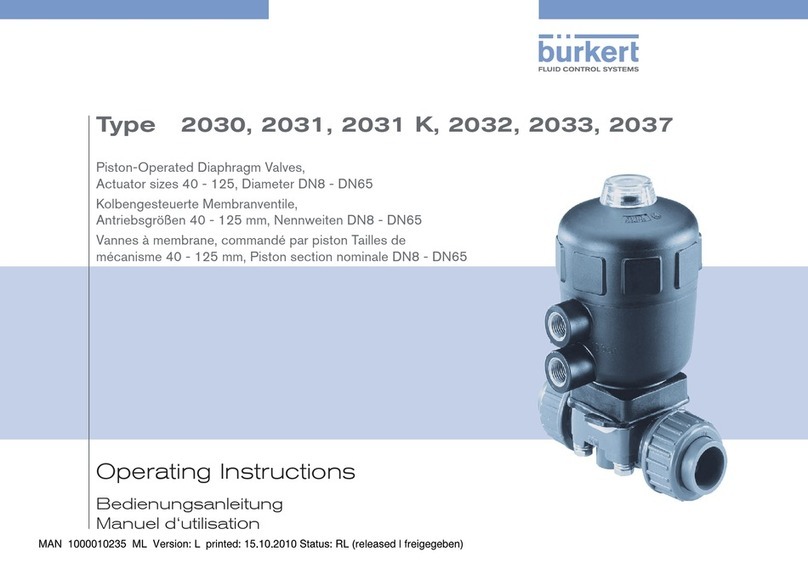
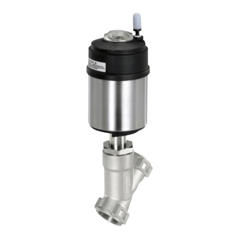
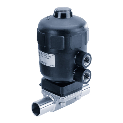
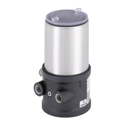
Burkert 8697 User manual

Operating Instructions
Bedienungsanleitung
Manuel d‘utilisation
Type 8697
Pneumatic Control Unit
Pneumatische Ansteuerung
Unité de commande pneumatique

We reserve the right to make technical changes without notice.
Technische Änderungen vorbehalten.
Sous réserve de modications techniques.
© Bürkert Werke GmbH & Co. KG, 2011 - 2018
Operating Instructions 1805/05_EU-ml_00810081 / Original DE

3
1. OPERATING INSTRUCTIONS ............................... 4
1.1. Symbols ............................................................................ 4
1.2.Denitionofterm/abbreviation........................................ 4
2. AUTHORIZED USE.................................................................. 5
2.1. Designs with explosion protection.................................... 5
3. BASIC SAFETY INSTRUCTIONS ............................................ 6
4. GENERAL INFORMATION ...................................................... 7
4.1. Contact address................................................................ 7
4.2. Warranty............................................................................ 7
4.3.Informationontheinternet................................................ 7
5. DESCRIPTION OF SYSTEM.................................................... 7
5.1.Congurationandfunction................................................ 7
6. TECHNICAL DATA ................................................................... 9
6.1.Conformity ........................................................................ 9
6.2. Standards.......................................................................... 9
6.3. Licenses ............................................................................ 9
6.4. Operating conditions......................................................... 9
6.5. Mechanical data.............................................................. 10
6.6. Type label (example)........................................................ 10
6.7. UL additional label .......................................................... 10
6.8. Pneumatic data............................................................... 10
6.9. Electrical data ................................................................. 11
7. INSTALLATION ...................................................................... 12
7.1.Safetyinstructions .......................................................... 12
7.2.Installationonprocessvalvesofseries21xx.................. 12
7.3.Installationonprocessvalvesofseries20xx.................. 15
7.4. Rotating the actuator module ......................................... 18
7.5.RotatingthePneumaticControlUnitforprocessvalves
belonging to series 20xx........................................................ 19
7.6.Manualactuationoftheactuatorviapilotvalve ............. 20
8. FLUID INSTALLATION ........................................................... 21
8.1.Safetyinstructions .......................................................... 21
8.2.Installingtheprocessvalve............................................. 21
8.3.PneumaticconnectionofthePneumaticControlUnit.... 21
9. ELECTRICAL INSTALLATION................................................ 22
9.1.Safetyinstructions .......................................................... 22
9.2. Electrical installation
with cable gland..................................................................... 23
9.3. Electrical installation with
circular plug-in connector...................................................... 26
9.4. Display elements: End position LEDs ............................. 27
9.5.Adjustmentofthemicroswitchesortheproximity
switches (option).................................................................... 28
10. SAFETY POSITIONS .......................................................... 29
11. ACCESSORIES.................................................................... 29
12. DISASSEMBLY .................................................................... 30
12.1.Safetyinstructions......................................................... 30
12.2. Disassembly the Pneumatic Control Unit ..................... 30
13. PACKAGING, TRANSPORT, STORAGE.............................. 31
english
Type 8697

4
Operating instructions
CAUTION!
Warns of a possible danger.
▶Failuretoobservethiswarningmayresultinamoderateor
minor injury.
NOTE!
Warns of damage to property.
▶Failuretoobservethewarningmayresultindamagetothe
deviceortheequipment.
Indicatesimportantadditionalinformation,tipsand
recommendations.
referstoinformationintheseoperatinginstructionsorin
other documentation.
▶Indicatesaninstructiontopreventrisks.
→Designates a procedure which you must carry out.
1.2. Denition of term / abbreviation
Theterm“device”usedintheseinstructionsalwaysstandsfor
the Pneumatic Control Unit Type 8697.
Theabbreviation“Ex”usedintheseinstructionsalwaysstands
for“explosion-protected”.
1. OPERATING INSTRUCTIONS
The operating instructions describesthe entire life cycle of the
device.Keeptheseinstructionsinalocationwhichiseasilyacces-
sibletoeveryuser,andmaketheseinstructionsavailabletoevery
newownerofthedevice.
The operating instructions contain important safety
information.
Failuretoobservetheseinstructionsmayresultinhazardous
situations.
▶The operating instructions must be read and understood.
1.1. Symbols
DANGER!
Warns of an immediate danger.
▶Failuretoobservethewarningwillresultinafatalorserious
injury.
WARNING!
Warns of a potentially dangerous situation.
▶Failuretoobservethewarningmayresultinseriousinjuries
or death.
english
Type 8697

5
Authorized use
2. AUTHORIZED USE
Non-authorized use of the Pneumatic Control Unit Type
8697 may be a hazard to people, nearby equipment and the
environment.
• Thedeviceisdesignedtobemountedonpneumaticactua-
torsofprocessvalvesforthecontrolofmedia.
• Donotexposethedevicetodirectsunlight.
• Useaccordingtotheauthorizeddata,operatingconditions
andconditionsofusespeciedinthecontractdocuments
and operating instructions. These are described in the chap-
ter entitled “6.Technicaldata”.
• Thedevicemaybeusedonlyinconjunctionwiththird-party
devicesandcomponentsrecommendedandauthorizedby
Bürkert.
• Inviewofthelargenumberofoptionsforuse,beforeinstal-
lation,itisessentialtostudyandifnecessarytotestwhether
thePneumaticControlUnitissuitablefortheactualuse
planned.
• Correcttransportation,correctstorageandinstallationand
carefuluseandmaintenanceareessentialforreliableand
faultlessoperation.
• Use the Pneumatic Control Unit Type 8697 only as intended.
2.1. Designs with explosion protection
DANGER!
Explosion hazard.
Improperuseinapotentiallyexplosiveatmosphererepresents
anexplosionhazard.
▶ObservetheinformationintheECDeclarationofConformity
as well.
▶FordesignswithExapproval,theinformationintheEC-Type
ExaminationCerticateandtheadditionalinstructionsofType
8697mustalsobeobserved.
2.1.1. Ex approval
TheExapprovalisonlyvalidifthemodulesandcomponentsautho-
rizedbyBürkertareusedasdescribedintheadditionalinstructions
forType8697.
The Pneumatic Control Unit may be used only in combination with
theadditionalcomponentsreleasedbyBürkert,otherwisetheEx
approvalwillbevoided!
Ifanyunauthorizedchangesaremadetothedevice,modulesor
components,theExapprovalwillalsobevoided.
english
Type 8697

6
Basic safety instructions
3. BASIC SAFETY INSTRUCTIONS
Thesesafetyinstructionsdonotmakeallowanceforany
• contingenciesandeventswhichmayariseduringtheinstallation,
operationandmaintenanceofthedevices.
• localsafetyregulations,wherebytheoperatorisresponsiblefor
theircompliance,bytheinstallationpersonneltoo.
DANGER!
Risk of injury from high pressure in the equipment/device.
▶Beforeworkingonequipmentordevice,switchothepressure
anddeaerate/drainlines.
Risk of electric shock.
▶Beforereachingintothedevice,switchothepowersupply
andsecuretopreventreactivation.
▶Observeapplicableaccidentpreventionandsafetyregulations
forelectricalequipmen.
General hazardous situations.
Topreventinjury,ensure:
▶Thatthesystemcannotbeactivatedunintentionally.
▶Installationandrepairworkmaybecarriedoutbyauthorized
technicians only and with the appropriate tools.
▶Afteraninterruptioninthepowersupplyorpneumaticsupply,
ensurethattheprocessisrestartedinadenedorcontrolled
manner.
▶Thedevicemaybeoperatedonlywheninperfectcondition
andinconsiderationoftheoperatinginstructions.
▶Thegeneralrulesoftechnologyapplytoapplicationplanning
andoperationofthedevice.
Topreventdamagetopropertyofthedevice,ensure:
▶Donotfeedanyaggressiveorammablemediaintothepres-
sure supply connection.
▶Donotfeedanyliquidsintothepressuresupplyconnection.
▶Do not put any loads on the body (e.g. by placing objects on
it or standing on it).
▶Donotmakeanyexternalmodicationstothedevicebodies.
▶Thedevicemaybeoperatedonlywiththetransparenthood
closed.
The Pneumatic Control Unit Type 8697 was developed
withdueconsiderationgiventotheacceptedsafetyrules
andisstate-of-the-art.Nevertheless,dangeroussituations
may occur.
english
Type 8697

7
General information
4. GENERAL INFORMATION
4.1. Contact address
Germany BürkertFluidControlSystems
Sales Center
Christian-Bürkert-Str.13-17
D-74653Ingelngen
Tel. : 07940 - 10 91 111
Fax: 07940 - 10 91 448
E-mail:[email protected]
International
Contactaddressesarefoundonthenalpagesoftheprinted
operating manual and also on the Internet at: www.burkert.com
4.2. Warranty
Thewarrantyisonlyvalid ifthedevice isusedas authorizedin
accordancewiththespeciedapplicationconditions.
4.3. Information on the internet
TheoperatinginstructionsanddatasheetsforType8697canbe
foundontheInternetat:www.burkert.com
5. DESCRIPTION OF SYSTEM
5.1. Conguration and function
The Pneumatic Control Unit Type 8697 can control single or double-
actingprocessvalves.ThePneumaticControlUnitType8697has
been optimized for integrated, modular installation on process
valvesofthe21xxseries(Elementactuatorsize∅ 50). The module
congurationpermitsavarietyofexpansionsteps.
For installation on the 20xx series there is a special model which
is described in Chapter “5.1.2”.
5.1.1. Pneumatic Control Unit for integrated
installation on 21xx series (Element
actuator size ∅50)
Cable gland M16 x 1.5 or Circular plug-in connector M12 x 1
Exhaust air connection
label: 3
Pressurelimitingvalve
(forprotectionagainsttoo
high internal pressure in case
oferror)
Pilot air port
label: 1
Transparent cap
Fig. 1: Conguration and function (1)
english
Type 8697

8
Description of system
Optical position indicator:
The device status is displayed on the Pneumatic Control Unit
(yellowmark).
Option: Electrical position feedback
Optionallymechanicallimitswitches(microswitches)orinductive
proximityswitchescanmeasurethevalveposition.
View without transparent cap:
Fastening screws (2x)
Screw terminals
Assemblyshaftfor
precision adjustment
oftheswitchcams
(onlyformodelwith
inductiveproximity
switches)
Openingforoptical
position indicator
Fig. 2: Conguration and function (2)
5.1.2. Model for control of process valves
belonging to the 20xx series
A special model enables the Pneumatic Control Unit Type 8697 to
beattachedtoprocessvalvesbelongingtothe20xxseries.
Thismodelhasadierentpneumaticconnectionmodulesothat
thepilotairportscanbeconnectedtotheoutsideoftheactuator.
Pilot air outlet 21
Fastening screws
(2x)
Pilot air outlet 22
Fig. 3: Connection module for process valves, 20xx series
english
Type 8697

9
Technical data
6. TECHNICAL DATA
6.1. Conformity
InaccordancewiththeEUDeclarationofconformity,thePneu-
maticControlUnitType8697iscompliantwiththeEUDirectives
(ifapplicable).
6.2. Standards
Theappliedstandards,whichverifyconformitywiththeEUDirec-
tives,canbefoundontheEU-TypeExaminationCerticateand/
ortheEUDeclarationofConformity(ifapplicable).
6.3. Licenses
Theproductisapprovedforuseinzone1,2,21and22inaccor-
dancewithATEXdirective2014/34/EUcategory2GDand3GD.
Observeinstructionsonoperationinanexplosion-risk
(Ex)area.ObservetheATEXadditionalinstructions.
TheproductiscULusapproved.InstructionsforuseintheUL
area see chapter “6.9.Electricaldata”.
6.4. Operating conditions
WARNING!
Solar radiation and temperature uctuations may cause
malfunctions or leaks.
▶Ifthedeviceisusedoutdoors,donotexposeitunprotected
to the weather conditions.
▶Ensure that the permitted ambient temperature does not exceed
themaximumvalueordropbelowtheminimumvalue.
Ambient temperature
withoutpilotvalve(feedbackhead) -20...+60°C
(-4...+140°F)
withpilotvalve(controlhead) -10...+55°C
(+14...+131°F)
withATEXapproval seeATEXadditional
instructions
Degreeofprotection
Evaluatedbythemanufacturer: IP65/IP67according
toEN605291)
EvaluatedbyUL: Cat.4xaccordingto
NEMA250standard
english
Type 8697

10
Technical data
6.5. Mechanical data
Dimensions see data sheet
Bodymaterial external PPS,PC
Sealing material external EPDM
internal FKM
Strokerangeofvalvespindle Microswitch 4...36mm
Proximityswitch 2...36mm
6.6. Type label (example)
D-74653 Ingelfingen
8697 -*-I2-E1-* PE51
single act pilot0.6 24V
Pmax 7bar
sw.ind.3wirePNP
Tamb0-+55°CREV.2
S/N1001
00248807
W15MA
Type;Featuresofthetype
code applicable to UL and ATEX
Controlfunction;pilotvalve;
supplyvoltagepilotvalve
Nominalpressure;limitswitch
Max. ambient temperature;
Releaseversion
Serialnumber;CEmark
Identicationnumber;
Dateofmanufacture
Bar code
Fig. 4: Example of type label
6.7. UL additional label
Limit switch: 10...30 V
Type 4X enclosure
Degreeofprotection
Supplyvoltage
limit switch
Fig. 5: Example of UL additional label (example)
6.8. Pneumatic data
Controlmedium neutralgases,air,Qualityclassesin
accordancewithDINISO8573-1
Dustcontent Class7 max.particlesize40μm,
max.particledensity10mg/m3
Watercontent Class3 max.pressuredewpoint-20°Cor
min.10°Cbelowthelowest
operating temperature
Oilcontent ClassX max.25mg/m3
Temperaturerange 0...+50°C(32...+122°F)
Pressurerange 3...7bar(43,5...101,5psi)
Airoutputofpilotvalve 7IN/min(foraerationanddeaeration,
QNn-valueaccordingtodenition
forpressuredropfrom7to6bar
absolute)
Connections
21xx (Element) Plug-in hose connector
SocketconnectionG1/8
20xx(Classic) SocketconnectionG1/8Connection
M5forconnectingtheactuator
english
Type 8697

11
Technical data
6.9. Electrical data
Connections CableglandM16x1.5,wrenchsize19
(clampingarea4...8mm)
with screw terminals
forcablecross-sections0.14...1.5mm²
Circularplug-inconnectorM12x1,8-pole
Supplyvoltage
Pilotvalve 24VDC±10%,residualripple10%
UL:NECClass2,24VDC,1W
Power consumption
ofpilotvalve 1W
Micro switch For maximum current load see table
Variantforsafetyextra-lowvoltage(0...48VAC/DC)
24V 48V
resistiveloadandsemi-conductor
load
2AAC
2ADC
2AAC
2ADC
inductiveload(cosϕ=0,3) 2AAC
2ADC
1,5AAC
1ADC
Variantforlowvoltage(50...250VAC/DC)1)
110/127V 220/240V
resistiveloadandsemi-conductor
load
2AAC
0,4ADC
2AAC
0,2ADC
inductiveload(cosϕ =0,3) 0,5AAC
0,2ADC
0,2AAC
0,1ADC
1) When used in the UL area, voltage and current are limited to 125 V AC
1 A. Also both micro switches must be fed from the same power supply.
Proximity switches
3-wirePNP10...30VDCmax.100mAper
proximity switch
2-wire24VDCnormallyopen10...30VDC
max.100mA,min.3mAperproximityswitch,
Voltagedrop<5VResidualcurrent<0,6mA
2-wireNAMUR8,2VDC,1,2/2,1mA
(actuated/notactuated)UL:NECClass2
Positionfeedback(option)
Protectionclass3acc.toDINEN61140(VDE
0140-1):
2microswitches0...48VAC/DC,
2initiators10...30VDC,normallyopencontactPNP
(3-wire),
2initiators10...30VDC,normallyopencontact
(2-wire),
2initiatorsNAMUR(8.2VDC)(2-wire)
Protectionclass2acc.toDINEN61140(VDE
0140-1):2microswitches50...250VAC/DC
english
Type 8697

12
Installation
7. INSTALLATION
Only for Pneumatic Control Unit without pre-assembled
processvalve.
7.1. Safety instructions
DANGER!
Risk of injury from high pressure in the equipment/device.
▶Beforeworkingonequipmentordevice,switchothepressure
anddeaerate/drainlines.
Risk of electric shock.
▶Beforereachingintothedevice,switchothepowersupply
andsecuretopreventreactivation.
▶Observeapplicableaccidentpreventionandsafetyregulations
forelectricalequipment.
WARNING!
Risk of injury from improper installation.
▶Installationmaybecarriedoutbyauthorizedtechniciansonly
and with the appropriate tools.
Risk of injury from unintentional activation of the system and
an uncontrolled restart.
▶Securesystemfromunintentionalactivation.
▶Followinginstallation,ensureacontrolledrestart.
7.2. Installation on process valves of
series 21xx
Procedure:
1. Install switch spindle
Transparent cap
Actuator
Pilot air ports
(plug-in hose con-
nectors with collets or
threaded bushings)
Fig. 6: Installation of the switch spindle (1), 21xx series
→Unscrew the transparent cap on the actuator and unscrew the
position display (yellow cap) on the spindle extension.
→For version with plug-in hose connector, remove the collets
(whitenozzles)frombothpilotairports(ifpresent).
english
Type 8697

13
Installation
O-ring
Spindle extension
Guideelement
Actuatorcover
Groovering
Switch spindle
Switch cam
3
max.5Nm
max.1Nm
Spacersleeve
Maximum
distance
Fig. 7: Installation of switch spindle (2), 21xx series
NOTE!
Improper installation may damage the groove ring in the
guide element.
Thegrooveringisalreadybepre-assembledintheguide
elementandmustbe“lockedintoposition”intheundercut.
▶Wheninstallingtheswitchspindle,donotdamagethegroove
ring.
→Push the switch spindle through the guide element.
NOTE!
Screw locking paint may contaminate the groove ring.
▶Donotapplyanyscrewlockingpainttotheswitchspindle.
→Tosecuretheswitchspindle,applysomescrewlockingpaint
(Loctite290)inthetappedboreofthespindleextensioninthe
actuator.
→CheckthattheO-ringiscorrectlypositioned.
→Screwtheguideelementtotheactuatorcover
(maximumtorque:5Nm).
→Screwswitchspindleontothespindleextension.Todothis,
thereisaslotontheupperside(maximumtorque:1Nm).
→Pushspacersleeve ontothe switchspindle up tothe guide
element.
Position switch cams on the switch spindle:
→Pushlowerswitchcamuptothespacersleeve.
→Pushupperswitchcamuntil3mmfromthestartoftheswitch
spindle.
Ensure that the distance between both switch cams is
maximum (see “Fig.7”).
english
Type 8697

14
Installation
2. Install sealing rings
Form seal
Pilot air ports
Caution:
Collets must not be
tted!
Installationof
theformseal
Fig. 8: Installing of the sealing rings, 21xx series
→Pulltheformsealontotheactuatorcover
(smaller diameter points upwards).
→CheckthattheO-ringsarecorrectlypositionedinthepilotair
ports.
WhenthePneumatic ControlUnitis beinginstalled,the
colletsofthepilotairportsmustnotbettedtotheactuator.
3. InstallationofthePneumaticControlUnit
Supports
Pilot air
ports
Fastening
screws
max.0,5Nm
Fig. 9: Installation of the Pneumatic Control Unit, 21xx series
→AlignthePneumaticControlUnituntilthesupportsofthePneu-
maticControlUnitcanbeinsertedintothepilotairportsofthe
actuator (see also “Fig.9”).
→PushthePneumaticControlUnit,withoutturningit,ontothe
actuatoruntilnogapisvisibleontheformseal.
NOTE!
Too high torque when screwing in the fastening screw does
not ensure degree of protection IP65 / IP67.
▶Thefasteningscrewsmaybetightenedtoamaximumtorque
of0.5Nmonly.
→Attach the Pneumatic Control Unit to the actuator using the
twosidefasteningscrews.Indoingso,tightenthescrewsonly
hand-tight(maximumtorque:0.5Nm).
english
Type 8697

15
Installation
7.3. Installation on process valves of
series 20xx
Procedure:
1. Install switch spindle
Transparent cap
Position indicator
Actuator
Fig. 10: Installation of the switch spindle (1), series 20xx
→Unscrew the transparent cap on the actuator.
→Usingahexagonsocketkey,unscrewtheorange/yellowposition
indicatorfromtheinsideoftheactuator.
→PresstheO-ringdownwardsintothecoveroftheactuator
(see “Fig.11”).
→Manually screw the switch spindle (and the plugged-on guide
element)togetherwiththeplasticpartontothespindleofthe
actuator,butdonottightenspindleyet.
Guideelement
O-ring
Plasticpartofthe
switch spindle
Switch cam
Switch spindle
Spindle (actuator)
Actuatorcover
Groovering
3
Spacersleeve
Maximum
distance
Fig. 11: Installation of the switch spindle (2), series 20xx
→Tighten the guide element with a wrench SW19 into the actuator
cover(torque:8.0Nm).
→Tighten the switch spindle on the spindle of the actuator.
Todothis,thereisaslotontheupperside(torque:1.0Nm).
→Pushspacersleeve ontothe switchspindle up tothe guide
element.
→Position switch cams on the switch spindle:
→Pushlowerswitchcamuptothespacersleeve.
→Pushupperswitchcamuntil3mmfromthestartoftheswitch
spindle.
Ensure that the distance between both switch cams is
maximum (see “Fig.11”).
english
Type 8697

16
Installation
2. InstallationofthePneumaticControlUnit
Fastening
screws
max.0.5Nm
Fig. 12: Installation of the Pneumatic Control Unit, series 20xx
→Push the Pneumatic Control Unit onto the actuator.
→PressthePneumaticControlUnitallthewaydownasfarasthe
actuator and turn it into the required position.
EnsurethatthepneumaticconnectionsofthePneumatic
ControlUnitandthoseoftheactuatoraresituatedpref-
erablyverticallyoneabovetheother(see“Fig.12”).
If they are positioned dierently, longer hoses may be
requiredotherthanthosesuppliedintheaccessorykit.
NOTE!
Too high torque when screwing in the fastening screw does
not ensure degree of protection IP65 / IP67.
▶Thefasteningscrewsmaybetightenedtoamaximumtorque
of0.5Nmonly.
→Attach the Pneumatic Control Unit to the actuator using the two
sidefasteningscrews.Indoingso,tightenthefasteningscrews
hand-tightonly(maximumtorque:0.5Nm).
3. Installationofthepneumaticconnectionontheactuator
Pilot air outlet 21
Lower pilot air port
Upper pilot air port
Pilot air outlet 22
Fig. 13: Installation of the pneumatic connection, 20xx series
english
Type 8697

17
Installation
→Screw the plug-in hose connectors onto the Pneumatic Control
Unit and the actuator.
→Usingthehosessuppliedintheaccessorykit,makethecon-
nection between the Pneumatic Control Unit and the actuator
withthefollowing“Tab.1:Pneumaticconnectiontoactuator”.
NOTE!
Damage or malfunction due to ingress of dirt and moisture.
▶TocomplywithdegreeofprotectionIP65/IP67,connectthe
pilotairoutletwhichisnotrequiredtothefreepilotairportof
the actuator or seal with a plug.
“Inrestposition”meansthatthepilotvalvesofthePneu-
matic Control Unit Type 8697 are isolated or not actuated.
If the ambient air is humid, a hose can be connected
between pilot air outlet 22ofthePneumaticControlUnit
andtheunconnectedpilotairportoftheactuatorforcontrol
function A or control function B. As a result, the spring
chamberoftheactuatorissuppliedwithdryairfromthe
ventductofthePneumaticControlUnit.
Control function Pneumatic connection Type 8697
with actuator
Pilot air outlet
Type 8697
Pilot air port
actuator
A
Processvalve
closed in rest
position
(byspringforce)
21
lower pilot air port
oftheactuator
22
should be con-
nected to the
upper pilot
airportofthe
actuator
B
Processvalveopen
in rest position
(byspringforce)
21
upper pilot
airportofthe
actuator
22
should be con-
nected to the
lower pilot air port
oftheactuator
Tab. 1: Pneumatic connection to actuator
english
Type 8697

18
Installation
7.4. Rotating the actuator module
The actuator module (Pneumatic Control Unit and actuator)
can be rotated for straight seat valves and angle seat
valvesonly.
The position of the connections can be aligned steplessly by
rotating the actuator module (Pneumatic Control Unit and actuator)
through360°.
Only the entire actuator module can be rotated. The Pneu-
matic Control Unit cannot be rotated contrary to the actuator.
The process valve must be in the open position for
alignmentoftheactuatormodule.
Actuator
module
Hexagon Hexagon
Nipple
Series 20xx
Series 21xx
Nipple
Fig. 14: Rotating the actuator module
DANGER!
Risk of injury from high pressure in the equipment/device.
▶Beforeworkingonequipmentordevice,switchothepressure
anddeaerate/drainlines.
Procedure:
→Clampvalvebodyinaholdingdevice(onlyrequirediftheprocess
valvehasnotyetbeeninstalled).
→ControlfunctionA:Openprocessvalve.
→Usingasuitableopen-endwrench,counterthewrenchaton
the pipe.
→Placesuitableopen-endwrenchonthehexagonofthe
actuator.
WARNING!
Risk of injury from discharge of medium and pressure.
Ifthedirectionofrotationiswrong,thebodyinterfacemay
become detached.
▶Rotate the actuator module inthespecieddirectiononly (see
“Fig.15”).
→Rotate counter-clockwise (as seen from below) to bring the
actuator module into the required position.
english
Type 8697

19
Installation
Open-end wrench
Fig. 15: Rotating with open-end wrench
7.5. Rotating the Pneumatic Control
Unit for process valves belonging
to series 20xx
Iftheconnectingcablesorhosescannotbettedproperlyfollowing
installationoftheprocessvalve,thePneumaticControlUnitcan
be rotated contrary to the actuator.
Procedure
→Loosen the pneumatic connection between the Pneumatic
Control Unit and the actuator.
→Loosenthefasteningscrews(hexagonsocketwrenchsize
2.5).
→Rotate the Pneumatic Control Unit into the required position.
Pneumatic
connection
Fastening
screw (2x)
Actuator
Pneumatic
Control Unit
Fig. 16: Rotating the Pneumatic Control Unit, series 20xx
NOTE!
Too high torque when screwing in the fastening screw does
not ensure degree of protection IP65 / IP67.
▶Thefasteningscrewmaybetightenedtoamaximumtorque
of0.5Nmonly.
→Tightenthefasteningscrewshand-tightonly
(maximumtorque:0.5Nm).
→Re-attach the pneumatic connections between the Pneumatic
ControlUnitandtheactuator.Ifrequired,uselongerhoses.
english
Type 8697

20
Installation
7.6. Manual actuation of the actuator
via pilot valve
Theactuatorcanbemovedwithoutapowersupplyfromtherest
positiontoitsendpositionandbackagain,whenthecontrolairis
connected.
Todothis,thepilotvalvemustbeactuatedwithascrewdriver.
NOTE!
The hand lever may be damaged if it is simultaneously
pressed and turned.
▶Donotpressthehandleverwhenturningit.
Pilot valve non
activated
(normal position)
Handlever
Handlever
totheleft
Pilot valve
activated
Handlever
to the right
Fig. 17: Pilot valve for aerate and deaerate the actuator
Move actuator to end position
→Turnthehandlevertotherightusingascrewdriver.
Note: Donotpressthehandleverwhenturningit
Move actuator back to the rest position
→Turnthehandlevertotheleftusingascrewdriver.
Note: Donotpressthehandleverwhenturningit
english
Type 8697
Table of contents
Other Burkert Control Unit manuals

Burkert
Burkert 2100 series User manual

Burkert
Burkert 2000 INOX User manual

Burkert
Burkert 2933 User manual

Burkert
Burkert 1066 User manual

Burkert
Burkert 6724 Series User manual

Burkert
Burkert 2030 User manual

Burkert
Burkert 3360 User manual

Burkert
Burkert 8647 AirLINE SP User manual

Burkert
Burkert 6027 User manual

Burkert
Burkert 6712 User manual

Burkert
Burkert 3232 User manual

Burkert
Burkert 2712 Series User manual

Burkert
Burkert 6211 EV User manual

Burkert
Burkert 0470 User manual

Burkert
Burkert 0641 User manual

Burkert
Burkert Type 2000 User manual

Burkert
Burkert 6240 User manual

Burkert
Burkert 3360 User manual

Burkert
Burkert EPS 21 ATEX 1 234 X User manual

Burkert
Burkert 770 User manual