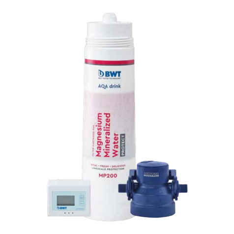
BWT AQA drink MPC400 User manual

Magnesium
Mineralized
Water
FILTER CARTRIDGES AND
FILTER HEAD FOR
PROTECT
Filter system for optimising drinking water
Installation and operating
instructions
AQA drink
EN
CARE
MMWPC_NeuesDesign_pink.indd 2 05.10.2018 08:43:45

Copyright © 2018 BWT. Alle Rechte vorbehalten. All rights reserved. Tous droits réservés. Todos
los derechos reservados. Tutti i diritti riservati. . Direitos reservados.
0 1 2 3
7
65
1× = 1 °dGH
10 ml
4
98
1 2 3
5
3
2
1
1
2
3
4
a
E
A C B
D
F
MM
TT
TT
MM YY
MM YY
MMWPC_NeuesDesign_pink.indd 3 05.10.2018 08:43:47

EN
Explanation of warning notices
IWARNING!
fIndicates a possibly dangerous situation which may cause risk of health.
ICAUTION!
fIndicates a possibly dangerous situation which may cause damage of property.
NOTE!
fAdditional information for an efficient and optimal operation.
Table of Contents
1 Scope of delivery.............................................................................................................................
2 Technical Data .................................................................................................................................
2.1 Dimensions und weights........................................................................................................
2.2 Operating conditions .............................................................................................................
2.3 Typical capacities and chlorine reduction ...........................................................................
3 Usage and design .............................................................................................................................
3.1 Assigned use...........................................................................................................................
3.2 Design and function of the filter system ..............................................................................
4 Operating and safety instructions .................................................................................................
4.1 Responsibility of the operator...............................................................................................
4.2 Warranty and exclusion of liability........................................................................................
4.3 Qualified personnel ................................................................................................................
4.4 Pressure ...................................................................................................................................
4.5 Operation after a break or shutdown / Replacement intervals.........................................
4.6 Disposal ...................................................................................................................................
5 Installing the filter system...............................................................................................................
5.1 Unpacking the filter system ...................................................................................................
5.2 Fitting the filter bracket .........................................................................................................
5.3 Determining filter capacity and bypass setting ..................................................................
5.4 Fitting the filter head .............................................................................................................
5.5 Installing a water meter .........................................................................................................
5.6 Installing/replacing the filter cartridge ................................................................................
6 Service and maintenance ................................................................................................................
7 Trouble shooting ..............................................................................................................................
8 Order numbers..................................................................................................................................
9 Table of filter capacities ..................................................................................................................
MMWPC_NeuesDesign_pink.indd 9 05.10.2018 08:43:47

EN
1 Scope of delivery
For professional installation of the filter system the following parts are required:
Filter cartridge (1) with hygienic cap and male thread for screwing into the filter head (2).
Filter head (2) with female thread for mounting the filter cartridge (1), suitable for all filter car-
tridge sizes with installation label. An Aquastop and two non return valves (inlet and outlet)
are installed in the filter head.
Bracket (3) for mounting the filter cartridge.
The filter cartridge has to be ordered separately from the filter head. The bracket is included in
the scope of delivery of the filter head.
2 Technical Data
2.1 Dimensions und weights
MPC400 MPC500
Total height without bracket, max. A mm (inch) 475 (18 /)502 (19 /)
Total height with bracket B mm (inch) 500 (19 /)527 (20 /)
Connection height C mm (inch) 421 (16 /)448 (17 /)
Distance from floor D mm (inch) 65 (2 /)65 (2 /)
Installation length E mm (inch) 125 (4 /)125 (4 /)
Filter cartridge Ø F mm (inch) 130 (5 /)147 (5 /)
Weight of dry filter cartridge, approx. kg (lb) 2.6 (5.7) 4.0 (8.8)
Weight of wet filter cartridge, approx. kg (lb) 4.3 (9.5) 6.1 (13.4)
2.2 Operating conditions
MPC400 MPC500
Connection thread (intake/outlet) /“ (BSP male)
Nominal flow L/h (US gal/h) 180 (48)
Working pressure range bar (psi) 2 – 8 (29 – 116)
Intake water pressure bar (psi) > 1.2 (> 17.4)
Pressure loss at 30 L/h (8 US gallons/h)¹ bar (psi) 0.05 (0.7) 0.05 (0.7)
Pressure loss at 60 L/h (16 US gallons/h)¹ bar (psi) 0.10 (1.5) 0.15 (2.2)
Pressure loss at 180 L/h (48 US gallons/h)¹ bar (psi) 0.40 (5.8) 0.50 (7.3)
Water temperature, min.–max. °C (°F) +4 to +30 (+39 to +86)
Ambient temperature, min.–max. °C (°F) +4 to +40 (+39 to +104)
Ambient temperature during transportation/
storage, min.–max. °C (°F) -20 to +40 (-4 to +104)
Bed volume L (US gal) 2.00 (0.5) 3.10 (0.8)
Operating position horizontal or vertical
Minimum flushing volume L (US gal) 5 (1.3) 9 (2.4)
Bypass setting “2”, with a 1.5 m (59.06 inch) hose DN8 fitted to both the intake and outlet.
2.3 Typical capacities and chlorine reduction
MP400 MP500
Typical capacity at 8 – 14 °dGH²,* L (US gal) 1370 (362) 1950 (515)
Chlorine reduction according to 5.5.2 EN 14898:2006 Class 1
Reduction (influent challenge concentration 2.0 mg/l)³ % > 50 %
The actual capacities in operation can be higher or lower than the capacities stated in the table. The capacities depend on the quality of the input water,
the flow rate, the intake water pressure and the flow continuity. The general hardness reduction is reached in accordance with Section 5.5.5 EN 14898:2006
for the stated capacities.
The concentration of chlorine in water entering the system was reduced to a concentration less than or equal to the permissible limit for water laving the
system, as specified in NSF/ANSI 42. While testing was performed under standard laboratory conditions, actual perfomance of the system may vary.*
1
2
MMWPC_NeuesDesign_pink.indd 10 05.10.2018 08:43:48

EN
T1
Typical filter capacities and bypass settings with respect to lime scale protection are
listed on the last pages of this operation manual.
T2
Typical filter capacities and bypass settings with respect to magnesium mineralisation are
listed on the last pages of this operation manual.
3 Usage and design
3.1 Assigned use
This BWT filter cartridge …
is only to be used for decarbonizing cold water fulfilling the legal requirements for drinking
water.
reduces total* hardness and thus protects appliances against lime scale deposits.
minearalizes drinking water with magnesium.
protects against bacteria, cryptosporidium, giardia, protozoa and microplastics and thus pro-
vides hygienically perfect water.
improves flavour of bevarages by removing substances responsible for taste and odor (eg.
chlorine).
filters particles* out of the water.
Any other use is deemed to be non-intended.
3.2 Design and function of the filter system
1 Pre-filtration: Removal of particles
2 Active carbon pre-filtration: Substances responsible for taste and odor (e.g. chlorine) are
removed, no oxidation of ion exchanger
3 Ion exchanger: Decarbonisation and mineralisation with magnesium
4 Active carbon filtration: removal of chlorine, also from bypass water
5 Ultrafiltration: retention of 99.9999% of all bacteria, cryptosporidia, giardia, protozoa, micro-
plastics, as well as natural dyes (e.g., humic acids)
4 Operating and safety instructions
Despite complying with all safety precautions, risks remain especially in case of misuse or
inappropriate handling. Each technical device is to be maintained and serviced regularly to
function properly.
IWARNING!
fAny use contrary to the intended use, e.g., if the filter system is fed with water that is not of drinking water quality, results in a health
hazard when the water is drunk:
- Microbiological hazard due to contamination with pathogenic germs
- Hazard from too high a concentration of heavy metals or organic contamination
fTo protect the drinking water, maintanance and any other work on the filter system has to be carried out considering national directives
for drinking water installations (e.g. DIN 1988, EN 1717) and applicable state and local regulations.
fIf the authorities or the operator of the water supply system release instructions to boil the potable water due to microbial contami-
nation it is necesary to boil the filtered water before consumption. If the drinking water quality is restored the filter system must be
replaced and connections cleaned.
fTwo type-tested non-return valves (in accordance with DIN EN 13959) are included in the filter head.
fSeparate the filter system from the water supply prior to maintenance work on the drinking water supply. Rinse the water line before
reconnecting the filter system.
fDisconnect the power supply of the appliance prior to installation.
3
MMWPC_NeuesDesign_pink.indd 11 05.10.2018 08:43:48

EN
ICAUTION!
fObserve all national directives for drinking water installations (e.g. DIN 1988, EN 1717) and applicable state and local regulations, general
sanitary requirements and technical data for the protection of drinking water.
fA check (shut-off) valve upstream of the filter system must be installed.
fUse only connections with gaskets or flat seals. Conical seals damage the filter head connections and will invalidate the warranty claim.
fThe appliance needs to be connected with hoses in accordance with DVGW W 543 or NSF 42/53.
fIf the product has been stored below freezing point (0 °C), leave the unpacked product at the ambient temperature of the installation
location for a minimum of 24 hours prior to operation.
fDo not install the filter system near heat sources, open fire places or naked flames.
fChemicals, solvents and vapours must not come into contact with the filter system.
fThe installation location must be protected against freezing and direct sunlight.
NOTE!
fFor installation and operation of the filter system, the BG regulation “Rules for Safety and Health Protection When Working in Kitchens”
of the “Food and Beverages” expert committee of BGZ (BGR111) must be observed. The filter system has been hygiene tested in accor-
dance with Section 7.4 DIN 18879–1.
fThe materials are selected in accordance with the requirements of DIN 18879–1 and EN 14898.
fThe pressure resistance of the filter system conforms to DIN 18879–1.
fThe filtered drinking water conforms to liquid category 2 in accordance with EN 1717.
fClean and descale the appliance, e.g. coffee machine, before firstly installing the filter system.
fFor immunocompromised people and infants it is recommended to boil the tap water before drinking. This also applies to filtered water.
fFor the protection against microbiological growth the filter cartridge contains a small amount of silver (“bacteriostatic”)*. There might
be a harmless release of silver in concentrations below the recommendations of the World Health Organization (WHO). The term
“bacteriostatic” indicates that the system limits the passage or growth of bacteria already existing in the incoming water*. It does not
mean that the water leaving the system is safer to drink than the water entering it.
fDuring the filtering process, the magnesium content rises slightly. If a special low-magnesium diet is to be followed, BWT recommends
to seek medical advice.
4.1 Responsibility of the operator
The installation and operating instructions must be kept in the immediate vicinity of the filter
system and must be accessible at any time.
The filter system may only be operated in a technically perfect state ensuring a safe
operation.
The instructions in this installation and operating manual must be followed entirely.
4.2 Warranty and exclusion of liability
BWT warrants to the original purchaser/consumer all equipment that it munufactures to be free
from defects in material and workmanship for a period of 2 years from the date of purchase. This
warranty is subject to exclusions and limitations
The notes and recommendations listed, as well as local drinking water and recycling regulations,
must be met. All information and notes in this installation and operating manual account for
the applicable standards and regulations, state-of-the-art technology as well as our expertise
in water treatment. BWT does not assume any liability for damages or subsequent/secondary
damages arising from:
Failure to comply with the instructions in this installation and operating manual
Improper use
Improper or faulty installation
Improper commissioning, operation, maintenance
Mechanical damage of the filter system
Unauthorized modifications
Technical modifications
Use of non-certified, non-approved components
MMWPC_NeuesDesign_pink.indd 12 05.10.2018 08:43:48
EN
4.3 Qualified personnel
Only authorised, trained persons and professionals shall install, commission and maintain the
filter system.
Authorised, trained persons have obtained instructions regarding the assigned tasks and
possible risks in case of misuse or improper operation.
Professionals are in a position to install, commission and maintain the device, as a result
of their technical training, knowledge and experience, as well as knowledge of applicable
regulations.
4.4 Pressure
ICAUTION!
fIf the maximum nominal pressure exceeds 8 bar (116 psi) a pressure reducer must be installed upstream of the filter system.
NOTE!
fInstalling a pressure reducer can reduce the flow.
fThe inlet pressure of the filter system should be higher than 1.2 bar (17.4 psi).
Pressure surges are to be avoided. If they do occur, the sum of pressure surge and idling
pressure must not exceed the nominal pressure of 8 bar (116 psi). The positive pressure surge
must not exceed 2 bar (29 psi) and the negative pressure shock must not fall below 50% of the
settling flow pressure (see DIN 1988 Part 2.2.4).
4.5 Operation after a break or shutdown / Replacement intervals
In the event of longer breaks in operation, close the shut-off valve in the inlet of the filter system.
After a break in operation exceeding two days (weekends, vacation, ...), rinse the filter system
with 4–5 litres (1.1–1.3 gallons) of water before reuse.
Replace the filter cartridge ...
on reaching the capacity stated in Section 3.2.
no later than 6 months after installation.
after a shutdown of 4 weeks or more.
4.6 Disposal
Dispose of exhausted filter cartridges, surplus parts and packaging according to local
regulations. If local collection points are available, recycle all product components to protect the
environment.
5 Installing the filter system
NOTE!
fDecarbonized water contains free carbonic acid. Only appropiate materials are to be used for installation. Original BWT accessoiries are
recommended.
5.1 Unpacking the filter system
Remove the filter system from the packaging. Inspect the delivery for completeness and
transport damage. Defective parts must be replaced immediately.
ICAUTION!
fFaulty or defect parts must be replaced immediately.
fAlways ensure a safe and clean working environment.
MMWPC_NeuesDesign_pink.indd 13 05.10.2018 08:43:48

EN
5.2 Fitting the filter bracket
ICAUTION!
fBefore installation, read Technical data (Chapter 2) and Operating/Safety instructions (Chapter 4).
fTo connect the filter system to the appliances only use hoses according to DVGWW 543 or NSF 42/53.
fWhen installing accessories (hoses, connection sets), observe the installation dimensions and bending radii.
To install the filter system, choose a location that enables simple connection to the water
mains.
The bracket has to be aligned and mounted to allow a convenient access and replacement of
the filter cartridge.
The filter system must be securely bolted to a wall using the bracket.
The filter system can be operated in a vertical or horizontal position.
For easy service and replacement of the filter cartidge after installation a minimum clearance/
distance of 65 mm (2.56 inches) is required at the bottom of the cartridge.
When installing the filter cartridge for horizontal operation, ensure that it is resting on the
floor.
5.3 Determining filter capacity and bypass setting
The general hardness can be requested from the water supplier or determined with a titration
test. The bypass setting can be selected based on the general hardness and its application.
The typical filter capacities are shown in Table T1 or T2 (last page).
There are four setting options for the bypass. The default bypass setting is “2”. The bypass
can be set by pressing the button “a” and twisting the cap on the filter head clockwise or
counter clockwise until the required bypass setting is reached and the cap snapps into place.
The bypass should be sealed with the included warranty label. Note month and year on the
label.
NOTE!
fBWT recommends to choose the size of the filter cartridge with its capacity to be due for replacement in 6 month intervals.
5.4 Fitting the filter head
ICAUTION!
fThe filter head is never to be left under mains water pressure without a mounted filter cartridge.
fThe tightening torque of the fittings (inlet/outlet) must not exceed 15 Nm!
NOTE!
fThe integrated Aquastop in the filter head prevents a water flow without mounted filter cartridge.
Insert the filter head into the filter bracket, observe the correct direction of flow.
Mount hoses (observe the bending radii!) for the water intake and outlet at the filter head.
Connect the water intake hose to the existing check/shut off valve in the intake.
Connect the water outlet hose to the appliance.
5.5 Installing a water meter
BWT recommends the installation of a water meter in the inlet of the filter cartridge in case
the filter system is used for a device without an integrated water meter (e.g. coffee machine)
which indicates the required replacement of the filter cartridge. With the water meter the filter
cartridge’s residual capacity can be determined at any time. Observe the operating instructions
of the BWT Aquameter.
2
4
5
6
MMWPC_NeuesDesign_pink.indd 14 05.10.2018 08:43:48

EN
5.6 Installing/replacing the filter cartridge
ICAUTION!
fThe filter cartridge may only be installed in a genuine BWT filter head.
fWork cleanly, avoid impurities on the filter system.
fClose the check/shut off valve before exchanging the filter cartridge.
Unpack the filter cartridge and remove the hygienic cap.
Before installing the filter cartridge mark the installation and replacement date (no later than
6 months) on the type label of the filter cartridge.
In case of replacement unscrew the filter cartridge clockwise out of the filter head.
Screw the new filter cartridge counter clockwise into the filter head.
Open the check/shut off valve and check the system for leaks.
NOTE!
fDuring commissioning, the filter has to be purged/flushed.
fTo avoid airlocks during initial installation, turn the cartridge upside down and flush the required volume through the flush valve. Whilst
flushing, press and release the button every 15 seconds for 2–3 seconds each time. This will agitate the resin and help remove any
trapped air bubbles.
fFor the best results, occasionally turn the cartridge upside down whilst it is in use. This will remove any accumulated gases that may be
trapped within the resin. After a few seconds, return the cartridge to the normal upright position.
fThe minimal flushing volume is given in Section 2.2. The volume of purge water is to be dismissed.
6 Service and maintenance
ICAUTION!
fFailure to respect the replacement intervals of the filter cartridge may cause damage to the downstream appliances.
fFailure to replace the filter head or the hoses after 5 years can cause property damage.
Drinking water is food Handle the filter system hygienically. Clean the filter system regularly
with a damp cloth. Work cleanly especially when replacing the filter car-
tridge. Avoid using alcohol based cleaners, acidic and strong chemicals.
Check for leaks Regularly
Check the pressure
hoses Regularly check for breaks, squeezes and pinch points. Replace damaged
hoses.
Break in operation/
shutdown After a break in operation exceeding two days, the filter cartridge should
be purged with a minimum of 4–5 liters (1.1–1.3 US gallons) of water.
Replace filter cartridge After 6 months (regardless of the residual capacity); after a shutdown of more
than 4 weeks
Replace filter head After 5, after 10 years the latest
Replace pressure hoses After 5 years
7
8
9
MMWPC_NeuesDesign_pink.indd 15 05.10.2018 08:43:48

EN
7 Trouble shooting
Error Cause Action
Filtered water cannot be
drawn
Water supply in general is
stopped or a valve is closed
Test all valves and open if necessary
Filter cartridge not screwed
properly into the filter head
Unscrew filter by ½ rotation and rein-
sert as far as possibel (Section 5.5)
Filter head fitted incorrectly Check flow direction according to the
arrow on the filter head and reverse
flow direction if necessary (Section 5.3)
Low water flow rate System pressure is too low Check system pressure (Section 4.4)
Aquastop in filter head
leaking while filter
cartridge is removed
Particles deposited in
Aquastop
Purge/flush filter system with
mounted filter cartridge (Section 5.6)
Threaded /screw
connection is leaking
Defective seal Check seal, replace if necessary
Air bubbles System not completely
purged
Repeat purging/flushing procedure
(Section 5.6)
Turbid or white water Process-related formation
of small bubbles of carbonic
acid
Turbidity vanishes after 5 minutes.
Heating element, boiler
in the appliance not
satisfactorily protected
against lime scale
Capacity of filter cartridge,
filter cartridge too small;
change in water hardness
from the water supplier.
Check total hardness (Section 5.3)
and filter capacity. Fit suitable filter
cartridge if necessary.
8 Order numbers
Order Number
Filter cartridge Magnesium Mineralized Water Protect Care MPC400 812595
Filter cartridge Magnesium Mineralized Water Protect Care MPC500 812596
9 Table of filter capacities
The filter capacities are listed in Table T1 or T2 at the end of this installation and operating
manual.
MMWPC_NeuesDesign_pink.indd 16 05.10.2018 08:43:48


VITAL, FRESH & DELICIOUS
LIMESCALE PROTECTION
HYGIENICALLY SAFE WITH
ULTRAFILTRATION
MMWPC_NeuesDesign_pink.indd 1 05.10.2018 08:43:38
BWT UK Limited
BWT House, The Gateway Centre, Coronation Road,
High Wycombe, Buckinghamshire. HP12 3SU
04194 838 100
bwt.com
This manual suits for next models
3
Table of contents
Other BWT Water Filtration System manuals

BWT
BWT Liff Powermag PM100S User manual

BWT
BWT MyAQUA Soft User manual

BWT
BWT Multipur AP Series User manual

BWT
BWT AQA drink User manual

BWT
BWT ECOSOFT MO5000 User manual

BWT
BWT PRO A User manual

BWT
BWT bestaqua 6 Manual

BWT
BWT AQA Detector User manual

BWT
BWT Woda Pure Energy User manual

BWT
BWT RTM CS S-500 User manual

BWT
BWT AQA nano User manual

BWT
BWT Multipur AP 65 User manual

BWT
BWT Infinity M User manual

BWT
BWT VIZION HRS-100 User manual

BWT
BWT Avanti WF User manual

BWT
BWT Infinity M User manual

BWT
BWT water + more bestmin M User manual

BWT
BWT AVANTI HWS User manual

BWT
BWT bestaqua 14ROC User manual

BWT
BWT Celsius 80 User manual