manuals.online logo
Brands
  1. Home
  2. •
  3. Brands
  4. •
  5. CAMDEN
  6. •
  7. Keypad
  8. •
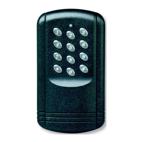
  9. CAMDEN CM-500SK User manual

CAMDEN CM-500SK User manual

5502 Timberlea Blvd, Mississauga, ON L4W 2T7 Tel: (905) 366-3377 Fax: (905) 366-3378
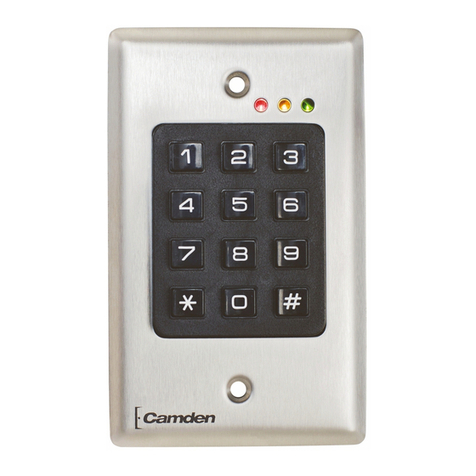
CM-500 SK
500 USER CODES
KEYPAD
B Request-to-exit PB1
E
Request
-
to
-
exit
PB2
M Common PB1 PB2
O
N/O contact relay 1
C Common relays
T N/O contact relay 2
V1
Varistor
ST1 Jumper for the reset
ST2
Jumper for relay 1
RL1 Door relay 1
RL2 Door relay 2
12
Input voltage
V Input voltage
1 Data
M Common M
This device comes with a varistor, which must be connected to the strike
terminal (or electromagnet) operated by the device.
If this product is connected to more than one strike, each of them should
have a varistor. The varistor controls the overload produced by the strike
coil – back emf.
If you are using a « Shear Lock » electromagnetic lock, it is recommended to use a separate power
supply than the one connected to t
he
CM
-
500SK
!
3
2
V
1
E
M
B
O
C
T
5
12
RL1
RL2
3
2
1
ST1
ST2
1
3
PB1
V1
Input voltage
12V AC/DC
Strike
ST2
1
3
1
3
N/C contact R
L1 (magnet)
PB2
1
2
3
4
5
6
7
8
9

0
#
Auxiliary keypad (see wiring)
Wiring diagram
PCB front view
N/O contact RL1 (strike)
Page 2 of 7
Technical specifications
Input voltage 12 VAC/DC
Outputs 2 relay outputs, contact N/O & N/C 3 amp@125V
User codes 500 user codes
Master code 5-digit programmable master code
Inputs 2 request to exit inputs
Keypad 12-digit keypad with built-in buzzer
Distance between
CM-500SK and auxiliary keypad Maximum 50 meter
(recommended cable 4 x 0.6 mm
2
)
Default values
Master code: 12345
Time outputs: 1 second
Key-in keypad time: 10 seconds
Audible signals
1 beep (short)
Pressing any key on the keypad
1 beep (long)
Validating data in programming mode: master code, user code
or time outputs.
Or user access code valid
2 beeps (short)
Entry in programming mode
Or exit from programming mode
4 beeps (short)
Incorrect user number keyed in
Or non valid user code or non valid time outputs
Visual signals
LED colour Normal mode Programming mode
LED off Standby
Green Door relay activated User number available
Red User number taken
Orange In programming mode
Orange flashing Standby Data computing error
Request to exit
THE REQUEST-TO-EXIT BUTTON ACTIVATES RELAY
1 AND RELAY 2 (THE OUTPUT, MOMENTARY OR
LATCHED,
AND THE TIME OUTPUTS ARE PROGRAMMABLE).
THE GREEN LED LIGHTS ON WHEN THE DOOR
RELAY IS ACTIVATED.
Page 3 of 7
Setting a new master code
1. Enter the master code twice (for the first use the master code default value is 12345). 2 beeps sound and
the LED lights on in orange to confirm entry in programming.
2. Enter 3 then the 5-digit of the new master code. The LED lights off during 1second and an audible beep
indicate that the code has been accepted.
3. Enter # to exit from the programming mode. 2 beeps confirm that you went back to the reading mode.
4. 4 beeps indicate a data computing error.
User numbers group and relays
A user code programmed in the first group addresses (000 to 249) operates relay RL1. A user code programmed in
the second group addresses (250 to 499) operates relay RL2. A user code can be programmed in the two groups.
Therefore, the user code will activate the two relays at the same time.
Setting Time Delays
Enter the master code twice (for the first use the master code default value is 12345). The orange LED and two
beeps sound to confirm entry in the programming mode.
Key-in keypad
time Enter 0 then the time in seconds:
10 for 10 seconds up to 99 for 99 seconds.
The LED turns off during 1 second and a beep
sounds to confirm that the time is accepted.
Programming User
Codes Enter address numbers from 000 to 249 to
operate door #1 and address numbers from 250 to
499 to operate door #2.
Door release time Enter 1, then the door release time in seconds:
01 for 1 second up to 99 for 99 seconds.
Enter 00 for a latched output.
The LED turns off for 1 second and a beep
sounds to confirm that the time is accepted.
Enter 2, then the door release time in seconds:
01 for 1 second up to 99 for 99 seconds.
Enter 00 for a latched output.
The LED turns off for 1 second and a beep
sounds to confirm that the time is accepted.
Enter # to exit from the programming mode. 2 beeps confirm that you went back to the reading mode.
4 beeps indicate a data computing error.
Page 4 of 7
Setting user codes
The user codes are programmed from the main unit (CM-500SK). The key # cannot be used in a code. To validate a user
code faster, it is recommended to enter the user code starting by the first user number of each group.
1. Enter the master code twice (for the first use the master code default value is 12345).
The orange LED and two beeps sound to confirm entry in programming mode.
2. Enter a user number (000 to 249) for door 1 and user number (250 to 499) for door 2.
The LED lights off for 1 second and one beep sounds.
3. If the LED is green, enter the 5-digit code the LED lights off for 1 second and one beep sounds.
The orange LED confirms that the code is accepted.
Or,
To skip the user number press #. The LED turns to orange and one beep sounds.
4. If the LED is red (the user number is taken), to delete the programmed code press * (star) twice, the LED turns green
or else enter another user number.
5. To exit from the programming mode, press #. 2 beeps sound to confirm that you left the programming mode.
When the LED is green, press the # key to a) leave a user number empty and then enter another user number or,
b) to continue programming. If the # key is not pressed while being in one of the user number and the LED is green, a data
computing error signal sounds. Enter a new user number.
Deleting or replacing programmed codes
1. Enter the master code twice (for the first use the master code default value is 12345).
The orange LED and 2 beeps sound to confirm entry in programming mode.
2. Enter the user number to delete (000 to 499). The LED turns off for 1 second and one beep sounds.
3. The LED turns red indicating that the current user number is not available.
4. Press . The LED turns green to confirm that the user number is now available.
5. Enter the new 5-digit user code.
Or,
6. Press the # key to continue.
7. Enter a new user number to program another user code.
Or,
8. To exit from programming mode, press #. 2 beeps confirm that the device is back to normal mode
(standby).
Reset of the master code and of the user codes
1. Place the jumper ST1 in 2-+3 position.
2. The green LED flashes during 5 seconds. The master code 12345 is set back as the default code.
3. One beep sounds. The LED turns to red and flashes.
4. Remove the jumper from the 2 + 3 position to go back to standby mode.
Or,
5. Keep the jumper in place 2 + 3 position to reset all the user codes.
6. The red LED flashes during 5 seconds and then stops during the deletion of the user codes.
7. Once all the user codes are deleted, the LED turns off.
8. Remove the jumper from the 2 + 3 position to go back to standby mode.
Page 5 of 7
Wiring of the auxiliary keypad
Wiring to CM-500SK 1 Data Yellow
M Common
Grey
Power supply Brown
Power supply White
User codes list
(make photocopy, if needed):
1
2 3
4 5 6
7 8 9

0 #
3
2
V
1
E
M
B
O
C
T
5
12
RL1
RL2
1
ST1
ST2
1
2
3
Input Voltage
12V AC/DC
Grey
Yellow
Brown
White
Operating the auxiliary reader:
Enter the 5-digit user code and press the # key. (Must enter 5-digits for the user code)
The # key is used as the ENTER key.
Page 6 of 7
User
number
Name User
number
Name User
number
Name User
number
Name
Time outputs Function
key Values Programmed values
Key-in keypad time 0 10 = 10 sec, 99 = 99 sec
Door release time relay 1 RL1 1 01 = 1 sec, 99 = 99 sec
Door release time relay 2 RL2 2 01 = 1 sec, 99 = 99 sec
Master Code 3 5-digit
Programmed by: Date
Building:
No.:
Street:
City:
Other information:
Filename : CM-500SK Instructions.doc
Part Number : 40-82B038
Version : 27/06/11 09:42
Page 7 of 7
CM-500SK Template
20,5 mm
105 mm
120 mm
135 mm
23 mm
43 mm
15 mm
38 mm
61 mm
75,5 mm
Wiring access
area
30 mm x 40 mm

Other CAMDEN Keypad manuals

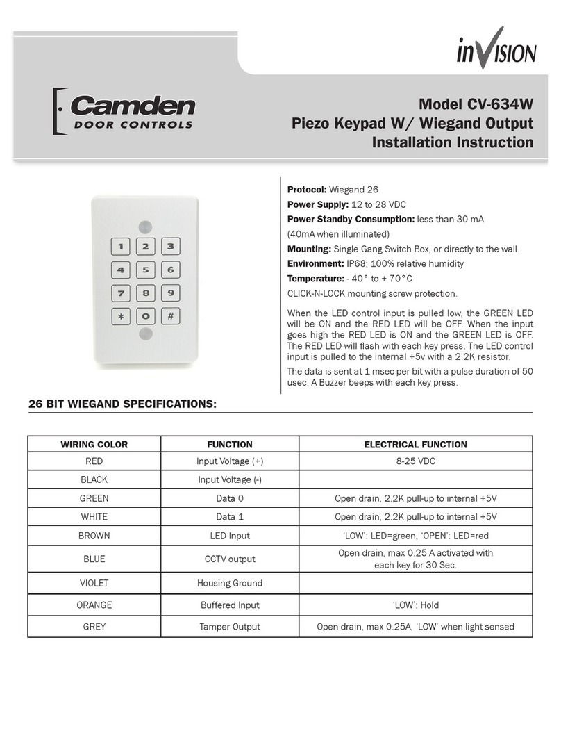
CAMDEN CV-634W User manual

CAMDEN

CAMDEN CV-634W User manual

CAMDEN 634W User manual

CAMDEN

CAMDEN 634W User manual

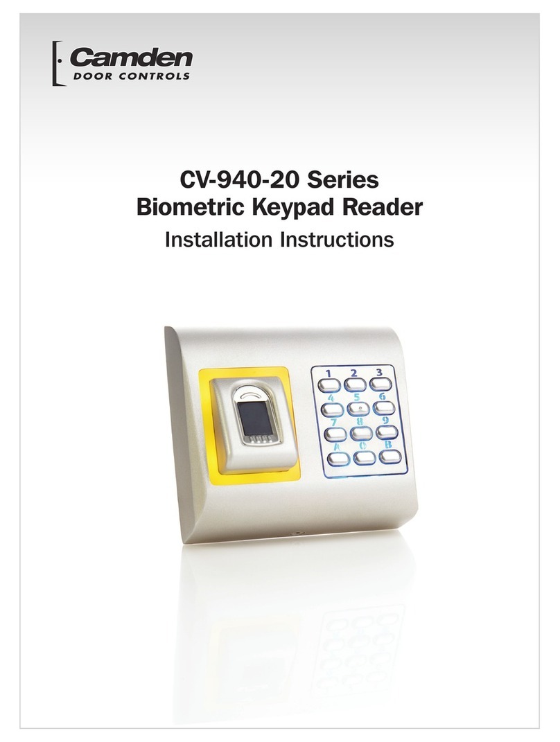
CAMDEN CV-940 Series User manual

CAMDEN

CAMDEN CV-940 Series User manual

CAMDEN inVISION CV-500PPK-V.2 User manual

CAMDEN

CAMDEN inVISION CV-500PPK-V.2 User manual

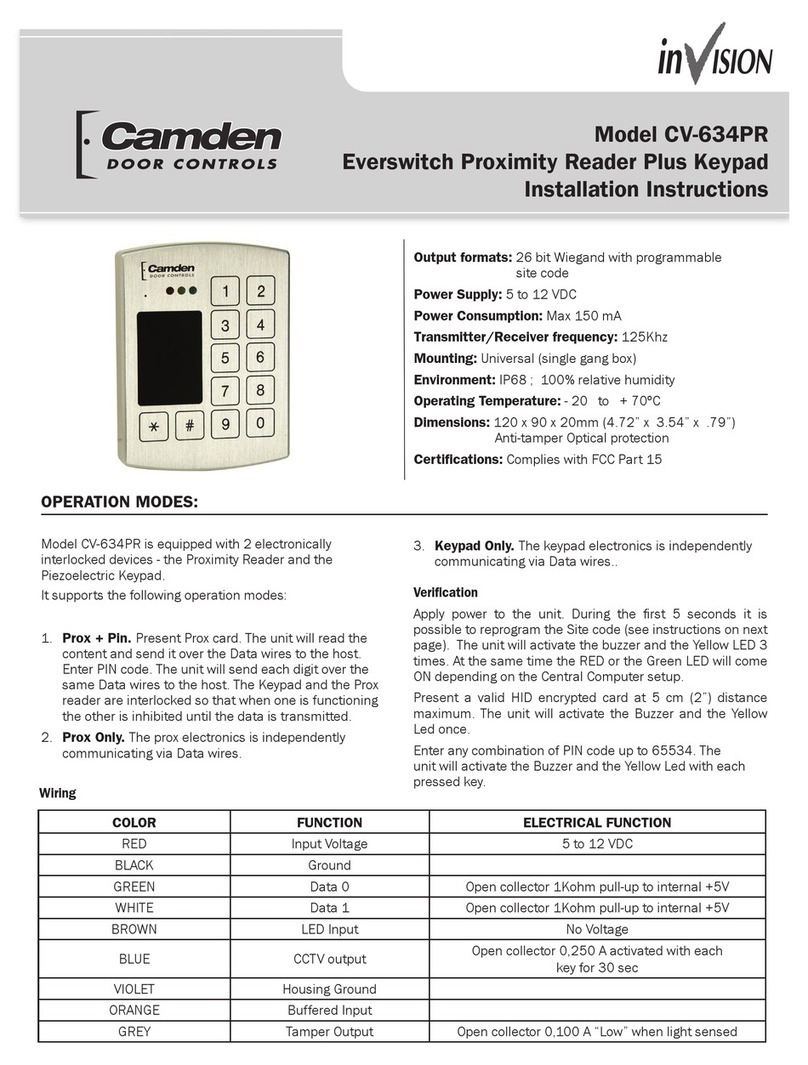
CAMDEN CV-634PR User manual

CAMDEN

CAMDEN CV-634PR User manual

CAMDEN CM-110SK User manual

CAMDEN

CAMDEN CM-110SK User manual

CAMDEN CM-120wV2 User manual

CAMDEN

CAMDEN CM-120wV2 User manual

CAMDEN CV-6268W User manual

CAMDEN

CAMDEN CV-6268W User manual

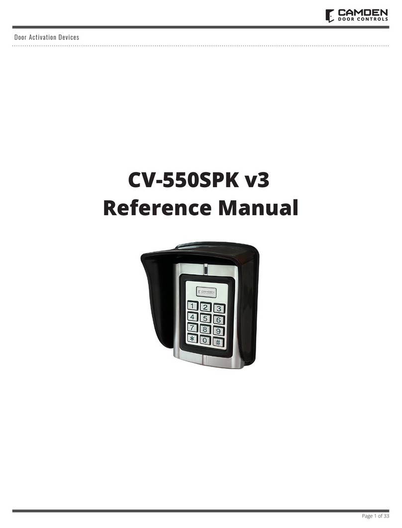
CAMDEN CV-550SPK V3 User manual

CAMDEN

CAMDEN CV-550SPK V3 User manual

CAMDEN 626SW User manual

CAMDEN

CAMDEN 626SW User manual

CAMDEN CV-626 User manual

CAMDEN

CAMDEN CV-626 User manual

CAMDEN CM-120TX User manual

CAMDEN

CAMDEN CM-120TX User manual

CAMDEN CM-626S Series User manual

CAMDEN

CAMDEN CM-626S Series User manual

CAMDEN CM-550SK V3 User manual

CAMDEN

CAMDEN CM-550SK V3 User manual

CAMDEN Invision CV-920 Series User manual

CAMDEN

CAMDEN Invision CV-920 Series User manual

CAMDEN CV-940-20 Series User manual

CAMDEN

CAMDEN CV-940-20 Series User manual

Popular Keypad manuals by other brands

AAA 6150RFAAA Installation and setup guide

AAA

AAA 6150RFAAA Installation and setup guide

Fermax MDS Installation and programming manual

Fermax

Fermax MDS Installation and programming manual

ACT ACT PRO 1030 manual

ACT

ACT ACT PRO 1030 manual

Cardin SSB Series manual

Cardin

Cardin SSB Series manual

Harman Kardon KP 1 Specifications

Harman Kardon

Harman Kardon KP 1 Specifications

CYP CR-KP1 Operation manual

CYP

CYP CR-KP1 Operation manual

Aeware k-35 Series Quick reference card

Aeware

Aeware k-35 Series Quick reference card

Aritech CS-175 Series user guide

Aritech

Aritech CS-175 Series user guide

Lenze AC Tech MC SERIES installation instructions

Lenze AC Tech

Lenze AC Tech MC SERIES installation instructions

Burg Wächter secuENTRY 7711 operating instructions

Burg Wächter

Burg Wächter secuENTRY 7711 operating instructions

Aeware in.k450 Tech book

Aeware

Aeware in.k450 Tech book

Lenze EPM-H410 operating instructions

Lenze

Lenze EPM-H410 operating instructions

Toshiba RKP007Z user manual

Toshiba

Toshiba RKP007Z user manual

Elmes Electronic KB1 quick start guide

Elmes Electronic

Elmes Electronic KB1 quick start guide

Clare Controls ClareOne CLR-C1-PNC Installation sheet

Clare Controls

Clare Controls ClareOne CLR-C1-PNC Installation sheet

FM Electronics 4180 quick start guide

FM Electronics

FM Electronics 4180 quick start guide

AMX MIO-PRESTIGE-S Dimensional drawing

AMX

AMX MIO-PRESTIGE-S Dimensional drawing

why pro WHY-KP user manual

why pro

why pro WHY-KP user manual

manuals.online logo
manuals.online logoBrands
  • About & Mission
  • Contact us
  • Privacy Policy
  • Terms and Conditions

Copyright 2025 Manuals.Online. All Rights Reserved.