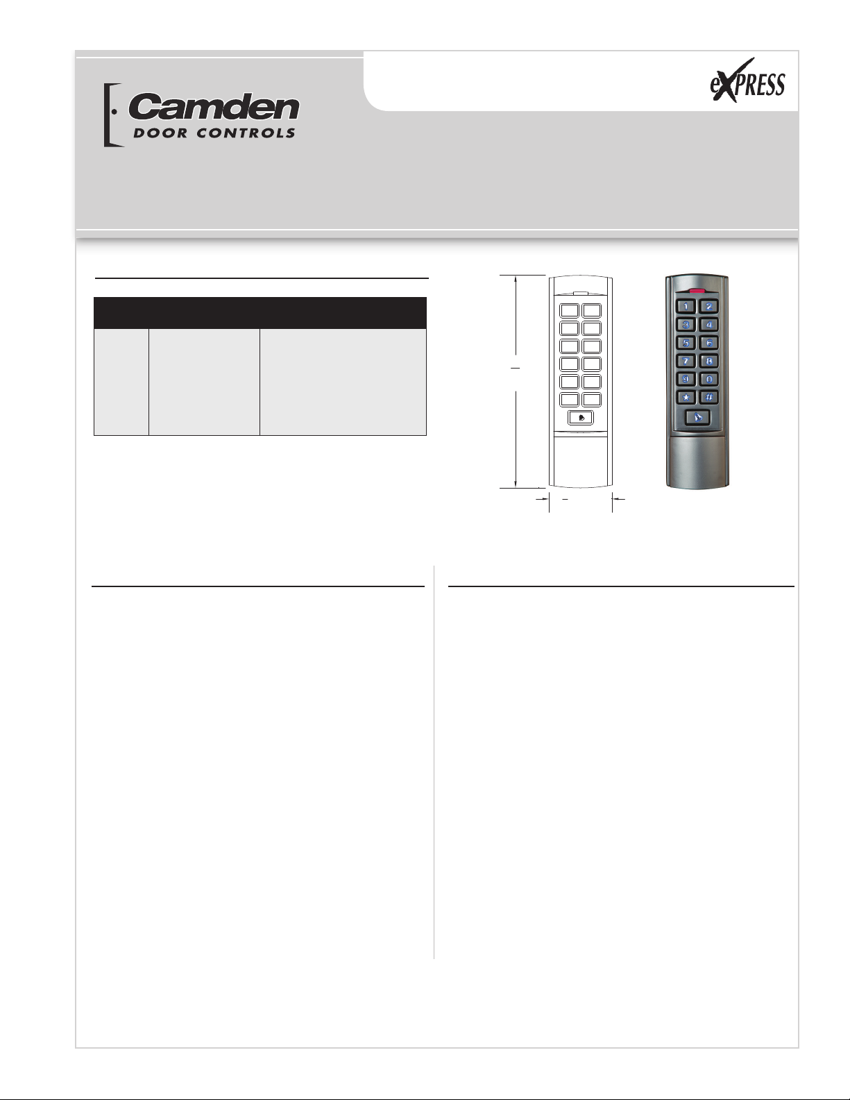
Standalone Keypad Installation Instructions
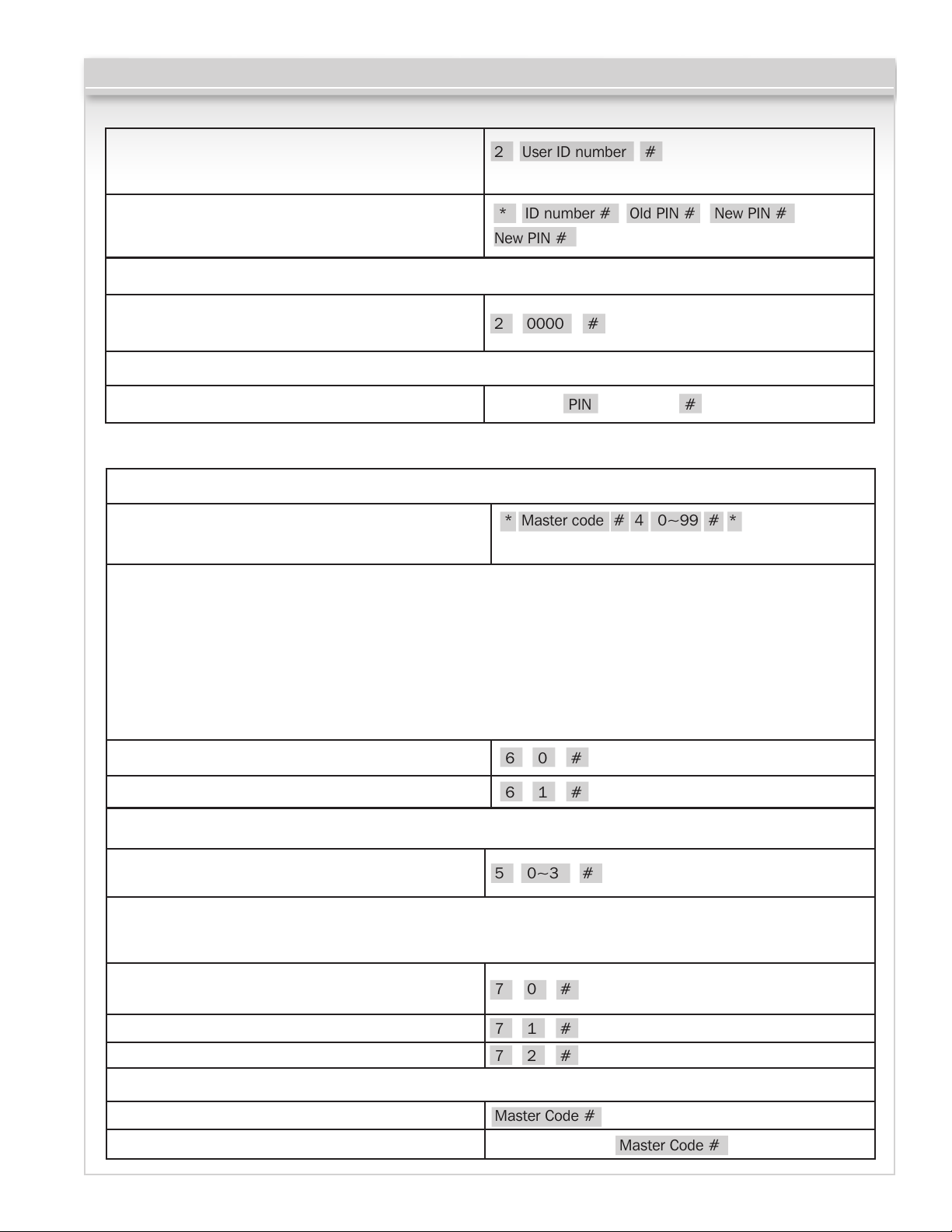
To delete a PIN user 2 User ID number # Users can be deleted
continuously without exiting programming mode
To change the PIN of a PIN user
(This step must be done out of programming mode)
* ID number # Old PIN # New PIN #
New PIN #
Page 5 of 6
To delete All users
To delete ALL users. Note that this is a dangerous
option so use with care 2 0000 #
To unlock the door
For a PIN user Enter the PIN then press #
Alarm output time
To set the alarm output time (0~3 minutes)
Factory default is 1 minute 5 0~3 #
Keypad Lockout & Alarm Output options. If there are 10 invalid cards or 10 incorrect PIN numbers in a
10 minute period either the keypad will lockout for 10 minutes, or the alarm will operate for 10 minutes, depending
on the option selected below.
Normal status: No keypad lockout or alarm
(factory default) 7 0 # (Factory default setting)
Keypad lockout enable 7 1 #
Alarm and inside buzzer operate 7 2 #
To remove the alarm
To reset the Door Forced Open Alarm Master Code #
To reset the Door Propped Open Alarm Close the door or Master Code #
Relay Output Delay Time
To set door relay strike time * Master code # 4 0~99 # *
0-99 is to set the door relay time 0-99 seconds
Door Open Detection
Door Propped Open Alarm. When used with an optional magnetic contact or built-in magnetic contact of the lock, if
the door is opened normally, but not closed after 1 minute, the inside buzzer will beep automatically to remind people
to close the door and continue for 1 minute before switching off automatically.
Door Forced Open Alarm. When used with an optional magnetic contact or built-in magnetic contact of the lock,
if the door is opened by force, or if the door is opened after 20 seconds of the electro-mechanical lock not being
closed properly, the inside buzzer and alarm output will both operate. The Alarm Output time is adjustable between
0~3 minutes with the default being 1 minute.
To disable door open detection. (Factory default) 6 0 #
To enable door open detection 6 1 #
11.2 Door Settings