CM-550SK V3
Waterproof Keypad/Controller
INSTALLATION INSTRUCTIONS
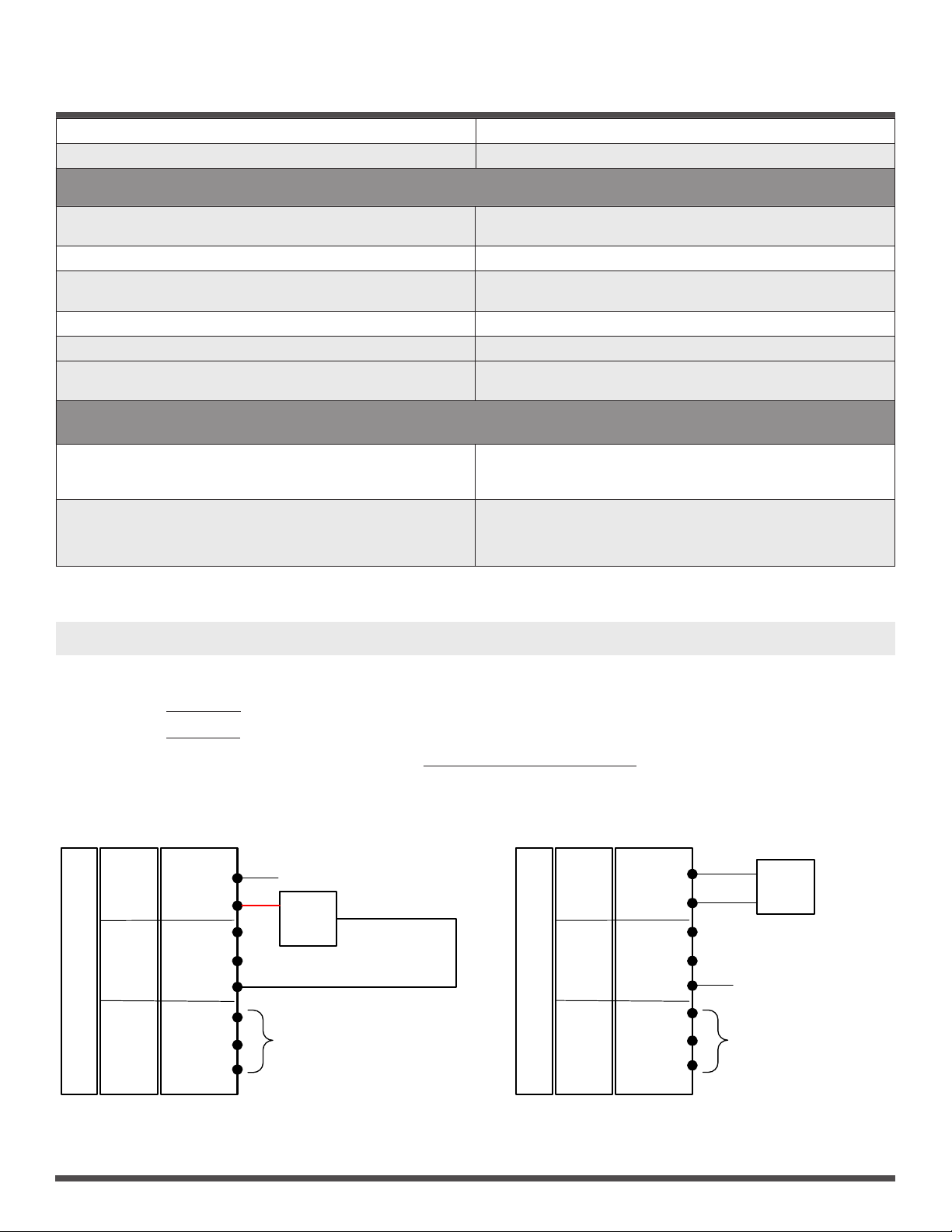
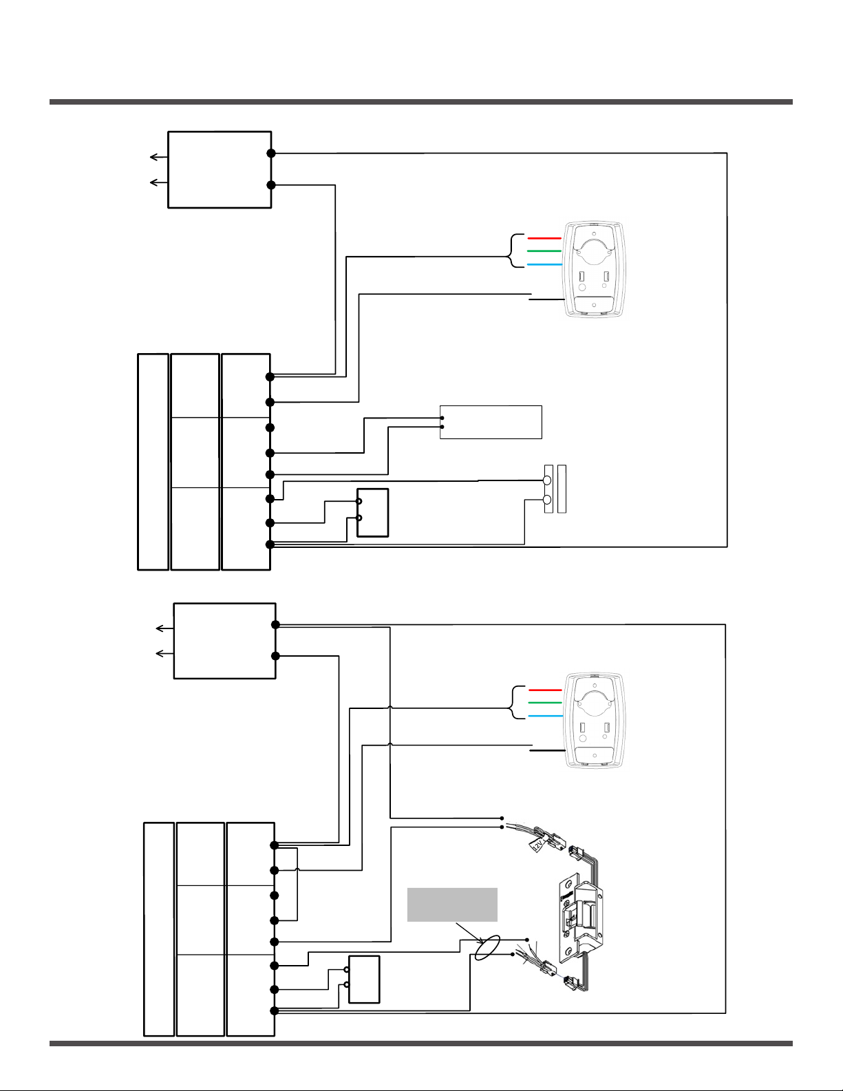
Door Activation Devices
(1) Digital Keypad CM-550SK V3
(1) User Manual
(1) Screw driver
(4) Wall plugs
(6 x 27 mm, used for mounting)
(4) Self tapping screws
(3.5 x 27 mm, used for mounting)
THIS PACKAGE INCLUDES:
1. DESCRIPTION
The CM- 550SK V3 is a back-lit single door multifunction standalone
access control keypad with a Wiegand input/output interface.
It is suitable for mounting either indoors or outdoors in harsh
environments. It is housed in a strong, sturdy and vandal proof Zinc
Alloy electroplated case. The electronics are fully potted so the
CM-550SK V3 is waterproof and conforms to IP68.
The CM-550SK V3 supports up to 20,000 Users. The PIN output
data can be congured for either 26 bit, 4-bit or 8-bit burst modes
making it compatible with most Access systems. These features make
the CM-550SKV3 an ideal choice for door access for commercial
and industrial applications such as factories, oces, warehouses,
laboratories, banks, and prisons.
2. SPECIFICATIONS
Input Power 10-28V AC/DC
Standby Current 35mA (Input VDC12V)
Operating Current: 100mA (Input VDC12V)
Working Humidity 0-95%
Working
Temperature -40°C to 60°C (-40F to 140F)
Alarm Output
(Digital) 1A @ 30VDC
Lock Relay 1A @ 30VDC
IP Rating 68
Note: When the keypad is idle the LED is solid RED.
In programming mode, the LED is ashing RED. The Master code
for programming must be changed to congure any part of the
CM-550SK and its parameters. All changes must be done within
programming mode.
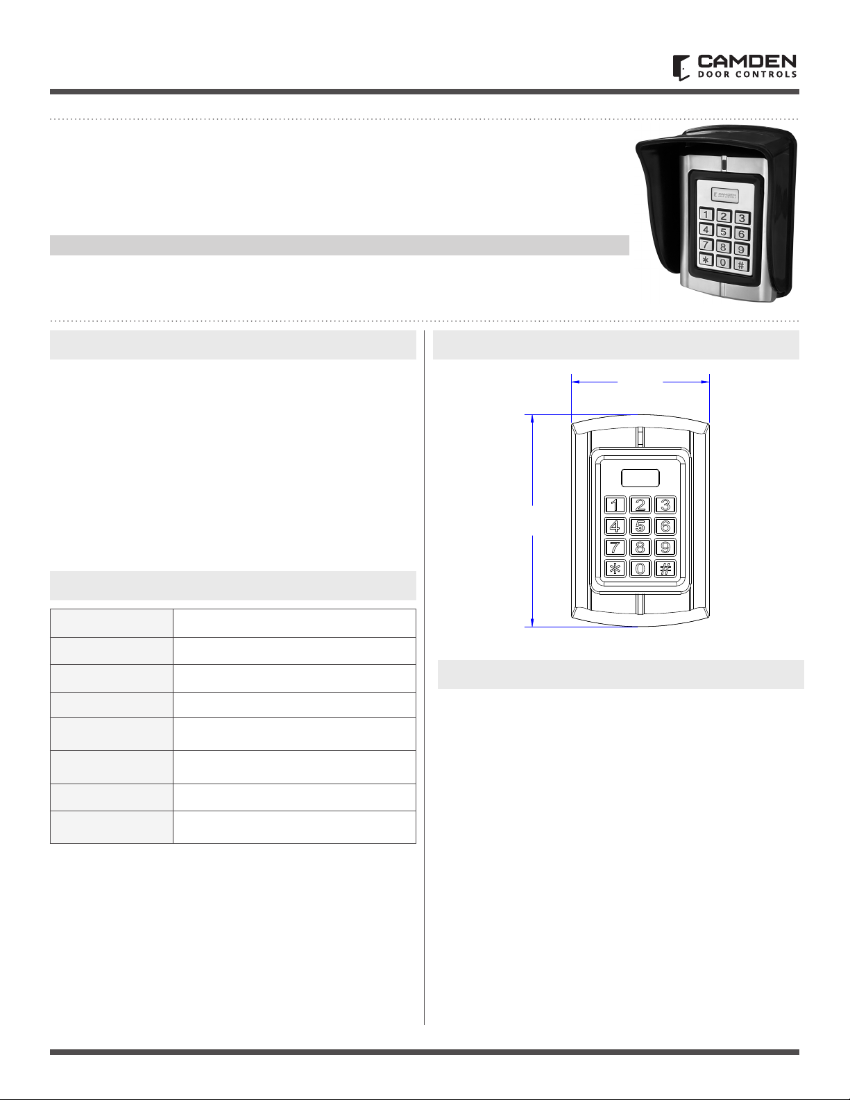
5"
[127mm]
3 1/4"
[82mm]
3. DIMENSIONS
4. OPERATION CONVENTIONS
• "Beep-" One long beep means the operation was correct. "Beep-
beep-beep" three short beeps mean the operation was incorrect.
The LED light turns green when the operation is successful.
• "#" means the previous operation was received by the system. It
is normally used at the end of entering digital numbers for a PIN
code, ID number, card number, or parameter. When you type this
key, the programming is nished.
• "*" means to cancel the current operation or go back to the
previous menu.
• The management menu is xed to 2 digits, from 00 to 99. Do not
press "#" on the keypad afterwards. After entering the 2 digits,
the LED will turn orange (or purple). If the operation fails, you will
hear "beep-beep-beep" three short beeps.
• Under the management menu operation mode, if there is no
activity detected of keys being pressed for over 30 seconds, it will
automatically revert to standby mode.