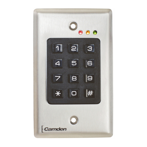
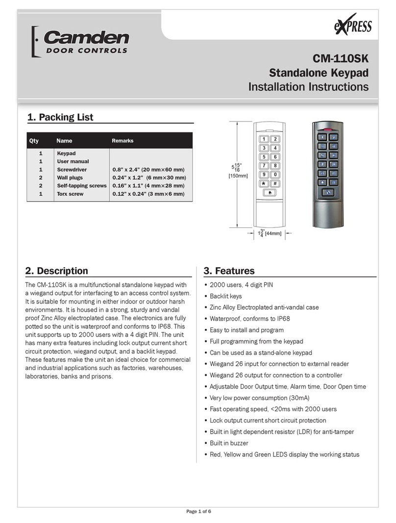
CAMDEN CV-550SPK V3 User manual

Page 1 of 33
CV-550SPK v3
Reference Manual
Door Activation Devices

Page 2 of 33
CV-550 SPK V3 REFERENCE MANUAL
INSTALLATION INSTRUCTIONS
TABLE OF CONTENTS
Page Numbers
1. Overview ........................................................................................................................................................................ - 4 -
1.1 Introduction ............................................................................................................................................................... - 4 -
1.2 Function features....................................................................................................................................................... - 4 -
1.3 Keypad exterior features ......................................................................................................................................... - 4 -
1.4 Technical parameters ............................................................................................................................................... - 5 -
1.5 Applicable models ..................................................................................................................................................... - 5 -
2. Installation, wiring and debugging ........................................................................................................................... - 6 -
2.1 Installation ................................................................................................................................................................. - 6 -
2.2 Wiring ......................................................................................................................................................................... - 6 -
2.3 Commissioning the system ...................................................................................................................................... - 12 -
3. Getting Started ............................................................................................................................................................ - 12 -
3.1 Enter management menu operation mode ........................................................................................................... - 13 -
3.2 Change admin password .......................................................................................................................................... - 13 -
3.3 Set controller to single-door mode ......................................................................................................................... - 13 -
3.4 Set door opening time to 2S ..................................................................................................................................... - 13 -
3.5 Add user card ............................................................................................................................................................. - 13 -
3.6 Add user PIN ............................................................................................................................................................... - 13 -
3.7 Exit management menu operation mode .............................................................................................................. - 14 -
3.8 User open door .......................................................................................................................................................... - 14 -
4. Basic Functions ............................................................................................................................................................. - 14 -
4.1 Management menu operations ................................................................................................................................ - 14 -
4.1.1 Change admin password .......................................................................................................................................... - 14 -
4.1.2 Set or delete super-open-password ......................................................................................................................... - 14 -
4.1.3 Set admin card ........................................................................................................................................................... - 14 -
4.1.4 Delete admin card ...................................................................................................................................................... - 15 -
4.1.5 Set keypad mode ........................................................................................................................................................ - 15 -
4.1.6 Limits types of reading card ..................................................................................................................................... - 15 -
4.1.7 Restore to default settings ....................................................................................................................................... - 15 -
4.1.8 Add user ...................................................................................................................................................................... - 16 -
4.1.9 Delete user .................................................................................................................................................................. - 16 -
4.1.10 Set open door methods ........................................................................................................................................... - 17 -
4.1.11 Set multi-card to open door ................................................................................................................................... - 17 -
4.1.12 Set lock working mode ............................................................................................................................................ - 17 -
4.1.13 Set limits user mode ................................................................................................................................................ - 17 -
4.1.14 Set open-time ........................................................................................................................................................... - 17 -
4.1.15 Door ajar alarm period ............................................................................................................................................. - 17 -
4.1.16 Set alarm-time............................................................................................................................................................ - 18 -
4.1.17 Set tampering alarm function ................................................................................................................................. - 18 -
4.1.18 Set alarm or doorbell output function ................................................................................................................... - 18 -
4.1.19 Set error lock out function ....................................................................................................................................... - 18 -

Page 3 of 33
CV-550 SPK V3 REFERENCE MANUAL
INSTALLATION INSTRUCTIONS
4.1.20 Set LED indicator light mode .................................................................................................................................. - 18 -
4.1.21 Adjust the brightness of the normally bright red indicator ............................................................................... - 18 -
4.1.22 Set key backlit mode................................................................................................................................................ - 19 -
4.1.23 Adjust brightness of key backlit............................................................................................................................. - 19 -
4.1.24 Set buzzer mode....................................................................................................................................................... - 19 -
4.1.25 Adjust key volume.................................................................................................................................................... - 19 -
4.1.26 Set the # key whether it can be used doorbell key.............................................................................................. - 19 -
4.1.27 Set doorbell key mode............................................................................................................................................. - 19 -
4.1.28 Set reader output format........................................................................................................................................ - 20 -
4.2 Admin card or PIN operation ..................................................................................................................................... - 22 -
4.2.1 Set-card operation ..................................................................................................................................................... - 22 -
4.2.2 Add-card operation.................................................................................................................................................... - 22 -
4.2.3 Delete-card operation ............................................................................................................................................... - 22 -
4.2.4 Super-open-card operation....................................................................................................................................... - 22 -
4.2.5 Super-open-password operation ............................................................................................................................. - 22 -
4.2.6 Anti-duress-card operation....................................................................................................................................... - 22 -
4.2.7 Authorization-card operation .................................................................................................................................. - 23 -
4.2.8 Normal-open-card operation ................................................................................................................................... - 23 -
4.3 Users operation ........................................................................................................................................................... - 23 -
4.3.1 Get user card or PIN ................................................................................................................................................. - 23 -
4.3.2 Change user PIN ........................................................................................................................................................ - 23 -
4.3.3 User open door ......................................................................................................................................................... - 23 -
4.4 Other operations ......................................................................................................................................................... - 24 -
4.4.1 Cancel alarming ........................................................................................................................................................ - 24 -
4.4.2 Admin password initialization ................................................................................................................................. - 24 -
4.4.3 Restore factory settings ........................................................................................................................................... - 24 -
4.5 Operation characteristics in dierent Keypad modes ........................................................................................... - 24 -
4.5.1 Operation characteristics in reader mode ............................................................................................................. - 24 -
4.5.2 Operation characteristics in single-door mode ..................................................................................................... - 25 -
4.5.3 Operation characteristics in interlock mode ......................................................................................................... - 25 -
4.5.4 Operation characteristics in demo mode .............................................................................................................. - 25 -
5. Management menu summary table ............................................................................................................................ - 25 -
5.1 Reader mode management menu summary table ................................................................................................. - 25 -
5.2 Single-door mode management menu summary table .......................................................................................... - 27 -
5.3 Interlock mode management menu summary table ............................................................................................. - 30 -
5.4 Demo mode management menu summary table ................................................................................................... - 30 -
6. Precautions in use........................................................................................................................................................... - 31 -
7. Common troubleshooting ............................................................................................................................................. - 31 -
8. Compatible peripherals ................................................................................................................................................. - 32 -
Page Numbers

Page 4 of 33
CV-550 SPK V3 REFERENCE MANUAL
INSTALLATION INSTRUCTIONS
1. OVERVIEW
1.1 Introduction
This version of keypad uses the new 32-bit microcontroller ARM core design with enhanced benecial functions. It’s a new
generation of multi-function access controller with a card reader mode, single-door mode, interlock mode, Demo mode etc.
All of them could be widely used in oce buildings, homes, schools, condominium, apartments, factories, fenced in yards and
other places.
1.2 Function features
• Built-in reader reads 125 kHz proximity credentials (EM& HID format).
• Vandal-resistant metal backlit keypad.
• Single-door controller can be set to Reader mode, Interlock mode and demo mode.
• Reader mode Wiegand output is congurable by the installer.
• Authentication by Card and PIN or Multi-cards to open the door.
• Administrator Super-open-card and Super-open-password to open door.
• Convenient administrator Add-card, Delete-card, Anti-duress-card, Authorization-card, and Normal-open card operation.
• Quick access to the management menu using admin password card feature.
• User card capacity up to 20,000, the admin programming card capacity up to 21.
• Quick access to the management menu using Set-card operation
• Doorbell button available using the “#” key once it is congured.
• In Reader mode, the keypad red and green LED indicators can be controlled externally.
• Innovative infrared tampering detection technology. The keypad can alarm 24/7 and it will not be aected by ambient light.
• Door Strike or maglock controlled by output relay contacts (NO, NC, COM).
• Alarm and doorbell signal output by MOS and it can be the driver of an alarm device or a doorbell.
1.3 Keypad exterior features

CV-550 SPK V3 REFERENCE MANUAL
INSTALLATION INSTRUCTIONS
Page 5 of 33
1.4 Technical parameters
• Working Voltage: AC/DC10-28V
• Standby current: ≤35mA (Input DC12V)
• Operating current: ≤100mA (Input DC12V)
• Working temperature: -40 °F + 140 °F ( -40 to 60 °C)
• Working humidity: 0-95%
• Lock signal relay contact current: ≤1A
• Alarm (or doorbell) signal MOS output current: ≤1A
• Distance of reading EM card: ≤ 2 inches (5 cm)
• Distance of reading HID card: ≤ 2 inches (5 cm)
1.5 Applicable models
This user manual applies to the following items:
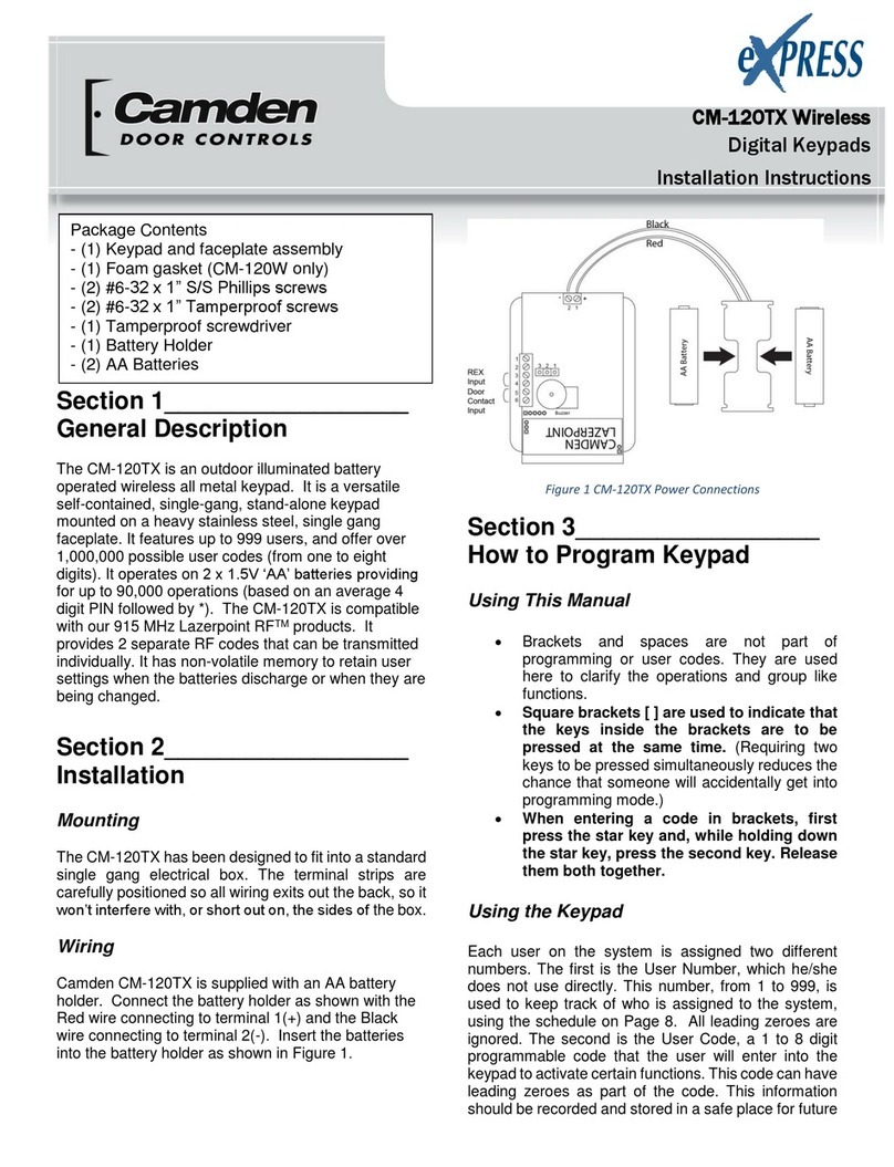
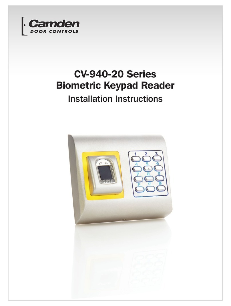
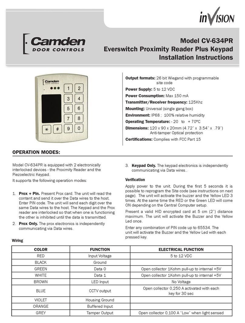
1. CM-550SPK v3 Stand Alone Keypad & Reader with 12 colored wire leads.
2. Rain /Privacy Shield for the keypad.

Page 6 of 33
CV-550 SPK V3 REFERENCE MANUAL
INSTALLATION INSTRUCTIONS
2. INSTALLATION, WIRING AND DEBUGGING
2.1 Installation
Using the Torx screwdriver remove the security fastening screw at the bottom of the device. Take o the bottom case and use
it to mark the position on the wall for the mounting holes. Use a drill to open a corresponding hole in the wall. The backplate
marks an outlet hole with a diameter greater than ¼” (8mm) and four plastic wall plugs holes with a diameter of ¼” (6mm). Use a
Phillips screwdriver to secure the backplate to the four matching plastic wall plugs with the four matching self-taping screws.
2.2 Wiring
Refer to the selected wiring diagram, cut the wire to the right length and cut o the excess feeding the cable through the wall
or into the backbox. Connect the remaining keypad wires as shown on the wiring diagram. Be careful not to connect the wrong
wires or short circuit, otherwise permanent damage to the keypad may occur. After checking, power on for a short time, conrm
the indicator light is normal and the buzzer beeps once. Otherwise, power o immediately and recheck the wiring properly. If all
is well, secure the keypad onto the backplate on the wall and tighten it with the security screw as below:
The product wiring colors and functions are shown in the following table:
Color Symbol Functions
Light
green AC2 One of the AC power supply terminal.
Blue NO Normal open terminal of Relay
Purple COM Common terminal of Relay
Orange NC Normal close terminal of Relay
Grey ALARM(BELL) Alarm (or doorbell) signal MOS drain output
Yellow OPEN(BEEP) Exit button input (or external control input of buzzer)
Brown D_IN(LED_G) Door contact input (or external control input of green LED)

CV-550 SPK V3 REFERENCE MANUAL
INSTALLATION INSTRUCTIONS
Page 7 of 33
8. SCHEDULING:
Red +12V(AC1) Positive DC power (or another terminal of AC power supply)
Black GND Ground
Green D0 Wiegand signal, D0 input or output (or RS232-TTL signal output: Tx)
White D1 Wiegand signal, D1 input or output (or RS232-TTL signal input : Rx)
Pink D_IN2(LED_R) External control input of red LED
AccessController
ALARM
+12V
NC
NO
COM
D0
D1
GND
LED_G
BEEP
LED_R
GREY
RED
ORANGE
BLUE
PURPLE
Green
White
BLACK
BROWN
YELLOW
PINK
WiringtheCV‐550SPKV3toanACCESSCONTROLLER
Mustbeconfiguredforreadermode
+12V
NormallyClosed
NormallyOpen
Common
Data0
Data1
Ground
GreenLED
Beeper
RedLED
Blue
Green
AlarmAnnunciator
Connectpositivewire
tocoloredwire
representingthe
preferredcolorofthe
domelight.
CamdenModel:CM‐AF142SO
(+ve)
Black (‐ve)
Red (+ve)
(+ve)
StandAloneKeypad
CamdenModel:CV‐550SPKv3

Page 8 of 33
CV-550 SPK V3 REFERENCE MANUAL
INSTALLATION INSTRUCTIONS
PowerSupply
12to24VDC
+12V
ALARM
NC
NO
COM
D0
D1
D_IN
OPEN
GND
RED
GREY
ORANGE
BLUE
PURPLE
Green
White
BROWN
YELLOW
BLACK
Blue
Green
AlarmAnnunciator
Connectpositivewireto
coloredwire
representingthe
preferredcolorofthe
domelight.
CamdenModel:CM‐AF142SO
(+ve)
PushtoExitSwitch
CamdenModel:CM‐30
Black
(‐ve)
Red
(+ve)
(+ve)
+
‐
NormallyOpen
CamdenModel:CV‐550SPKv
3
120VAC
WiringtheCV‐550SPK
V3
toanexternalcardreaderanddoorstrike
DoorPositionSwitch
5‐16VDC
Ground
Data0
Data1
ExternalWiegandCardReader
NormallyClosed
DoorStrike12VDC
(+)
(‐)
(CanbereplacedwithaMOV)
CamdenModel:
CX‐ED1079
D1
CamdenModel:CV‐7400
StandAloneKeypad
Mustbeconfiguredforsingledoormode
PowerSupply
12to24VDC
+12V
ALARM
NC
NO
COM
D0
D1
D_IN
OPEN
GND
RED
GREY
ORANGE
BLUE
PURPLE
Green
White
BROWN
YELLOW
BLACK
Blue
Green
AlarmAnnunciator
Connectpositive
wiretocolored
wire
representingthe
preferredcolor
ofthedome
light.
CamdenModel:CM‐AF142SO
(+ve)
PushtoExitSwitch
CamdenModel:CM‐30
Black
(‐ve)
Red
(+ve)
(+ve)
+
‐
Maglock
NormallyOpen
CamdenModel:CV‐550SPKv
3
120VAC
WiringtheCV‐550SPK
V3
toanexternalcardreaderandmaglock
DoorPositionSwitch
CamdenModel:CX‐90/91Series
5‐16VDC
Data0
Data1
Ground
WiegandCardReader
NormallyClosed
CamdenModel:CV‐7400

CV-550 SPK V3 REFERENCE MANUAL
INSTALLATION INSTRUCTIONS
Page 9 of 33
INTERLOCK APPLICATION : Two keypads wired together
Green
AlarmAnnunciator
CamdenModel:CX‐LED2
PUSHTOEXIT
PushtoExitSwitch
CamdenModel:CM‐30
Black
(‐ve)
Red
(+ve)
(+ve)
NormallyOpen
CamdenModel:CV‐550SPK
WiringtheCV‐550SPK
V3
toanexternalcardreaderanddoorstrike
DoorPositionSwitch
NormallyClosed
DoorStrike
(+)
(‐)
(Canbereplaced
withaMOV)
CamdenModel:
CX‐ED1079
D1
StandAloneKeypad
MustbeconfiguredforINTERLOCKmode
CamdenModel:CV‐550SPK
StandAloneKeypad
PUSHTOEXIT
NOGNDNOGND
TRIGINPUTRESETFACP1FACP2 +AUX‐COM‐STRIKE+LOCK+
XFMR‐BATT+
115
vac
CamdenModel:CX‐PS10UL
PowerSupply
SW2
SW2
position
mustbe
OFF.
XFMR‐BATT+
115
vac
CamdenModel:CX‐PS10UL
PowerSupply
SW2
SW2
position
mustbe
OFF.
NOGNDNOGND
TRIGINPUTRESETFACP1FACP2 +AUX‐COM‐STRIKE+LOCK+
Maglock
CamdenModel:CX‐90/91
NormallyClosed
(+)
(‐)
(Canbereplaced
withaMOV)
D1
Maglock
CamdenModel:CX‐90/91
DoorStrike
CamdenModel:
CX‐ED1079
DoorPositionSwitch
PushtoExitSwitch
CamdenModel:CM‐30
Black
(‐ve)
NormallyOpen

Page 10 of 33
CV-550 SPK V3 REFERENCE MANUAL
INSTALLATION INSTRUCTIONS
Green
AlarmAnnunciator
CamdenModel:CX‐LED2
PUSHTOEXIT
PushtoExitSwitch
CamdenModel:CM‐30
Black
(‐ve)
Red
(+ve)
(+ve)
NormallyOpen
CamdenModel:CV‐550SPK
WiringtheCV‐550SPK
V3
toanexternalcardreaderanddoorstrike
DoorPositionSwitch
NormallyClosed
DoorStrike
(+)
(‐)
(Canbereplaced
withaMOV)
CamdenModel:
CX‐ED1079
D1
StandAloneKeypad
MustbeconfiguredforINTERLOCKmode
CamdenModel:CV‐550SPK
StandAloneKeypad
PUSHTOEXIT
NOGNDNOGND
TRIGINPUTRESETFACP1FACP2 +AUX‐COM‐STRIKE+LOCK+
XFMR‐BATT+
115
vac
CamdenModel:CX‐PS10UL
PowerSupply
SW2
SW2
position
mustbe
OFF.
XFMR‐BATT+
115
vac
CamdenModel:CX‐PS10UL
PowerSupply
SW2
SW2
position
mustbe
OFF.
NOGNDNOGND
TRIGINPUTRESETFACP1FACP2 +AUX‐COM‐STRIKE+LOCK+
Maglock
CamdenModel:CX‐90/91
NormallyClosed
(+)
(‐)
(Canbereplaced
withaMOV)
D1
Maglock
CamdenModel:CX‐90/91
DoorStrike
CamdenModel:
CX‐ED1079
DoorPositionSwitch
PushtoExitSwitch
CamdenModel:CM‐30
Black
(‐ve)
NormallyOpen

CV-550 SPK V3 REFERENCE MANUAL
INSTALLATION INSTRUCTIONS
Page 11 of 33
Stand Alone Access Control Keypad
AC2
AC1
D_IN
OPEN
GND
NO
COM
NC
Light Green
RED
BROWN
YELLOW
BLACK
BLUE
PURPLE
ORANGE
Camden Model: CV-550SPK V3
Stand Alone Access Control Keypad
AC2
AC1
D_IN
OPEN
GND
NO
COM
NC
Light Green
RED
BROWN
YELLOW
BLACK
BLUE
PURPLE
ORANGE
Camden Model: CV-550SPK V3
Power
Supply
DC
10-28V
+ve
-ve
Not Used
Relay contacts
To trigger door
strike or
Maglock
Power
Supply
AC
10-28V
Not Used
Relay contacts
To trigger door
strike or
Maglock
Camden Model: CX-TRP-612DC
Camden Model: CX-TRP-4016
Wiring for DC Power (AC1 & gniriW)DNG for AC Power (AC1 & AC2)
Note: Connect corresponding power as shown above to prevent damage to the keypad.

Page 12 of 33
CV-550 SPK V3 REFERENCE MANUAL
INSTALLATION INSTRUCTIONS
2.3 Commissioning the system
Once the keypad is powered, conduct the following test, Getting Started, until you can open the door by reading a card,
input PIN or exit button.
3. GETTING STARTED
Writing Conventions:
• Keypad operation only can be used between these12 buttons; “0123456789*#”
• “…” means continue similar operation as indicated from previous operations.
• “,”is not an actual operation, it’s just punctuated.
• “()” means the series of numeric numbers which will be typed into the keypad, like a PIN code, ID number ,card number etc.
Operation Conventions:
• “Beep-”one long beep means the operation was correct. “beep-beep-beep” three short beeps mean operation was
incorrect. LED light turn to green means operation was successful.
• “#” means previous operation was received by system, it normally used at the end of entering the digital numbers of PIN
code, ID number, card number or parameter, when you type this key, it means input is nished.
• “ * ” means cancel current operation or back to previous menu
• Management menu is xed to 2 digits, from 00~99, Don’t press “#” on the keypad afterwards. After entering the 2 digits, the
LED will turn to orange (or purple), if the operation failed you will hear “beep-beep-beep”3 short beeps.
• Under the management menu operation mode, if there is no activity detected without any operation over 30 seconds, it will
revert to standby mode automatically.
Indicator light and buzzer prompt:
Operation Status Indicator light Buzzer
Standby mode Red
Successful operation Green A long beep
Operation incorrect 3 short beeps
When admin card enter 2 short beeps
When admin card exit A long beep
Press digit key A short beep
Press * key A long beep
Inputting opening door PIN Red slow ash
Both read card and input PIN Mode,
after reading the card Red slow ash
Multi-card reading open the door, when the card
reading is not over yet Red slow ash
Enter the rst zone admin main menu Red slow ash
Enter the rst zone setting status Orange
The rst unlock Green
Alarm Red quick ash Alarm Sound

CV-550 SPK V3 REFERENCE MANUAL
INSTALLATION INSTRUCTIONS
Page 13 of 33
3.1 Enter management menu operation mode
* (Hold on for more than 2 seconds), (Input admin password) #
3.2 Change admin password
00, (New admin password) #, (Repeat new admin password) #
Note: New admin password must be a 6 digit number.
3.3 Set controller to Single-door mode
Factory default setting is in single door mode. To conrm the mode, the user can set it again by following the steps: 03, 1#
3.4 Set door opening time to 2S
The factory default door opening time is 2 seconds. If user is not sure about the time period, set it again following steps:
34, 2 #
3.5 Add User Card
10, read card, read card …repeat the operation till the last user card.
Note: the keypad can read multiple card credentials continuously (Batch loading). When you hear a long “beep- “and the
indicator light turns to green it means the new card was added successfully. After nishing enrolling the last card, press the
* key to exit the add user card status.
3.6 Add User PIN
11(ID) #, (User PIN) #, (ID) #, (User PIN) #, …repeat the operation till the last user PIN.
Note: The user ID range is from 1 to 20,000 and must not be added before. User PIN is a 4~6 digits number and this number
must not be 1234. Controller can add more users continuously, after the last user PIN, press the * key to exit the add User
PIN status.
Note: Admin password is a 6 digits number, 888888 is the factory default admin password. The user must
change the admin password when they use the keypad. A new admin password is required, otherwise the
user cannot continue other operations. After inputting the new admin password, the LED light will ash
green once and then back to red ash status, all of the other operations will be similar.

Page 14 of 33
CV-550 SPK V3 REFERENCE MANUAL
INSTALLATION INSTRUCTIONS
3.7 Exit Management menu operation mode
In Management menu operation mode, press * more than once until the indicator light turns to red and always bright which con-
rms you have exited the Management menu operation mode.
3.8 User open door
When the indicator light is red and always bright, read card, or (input user PIN) #, or press exit button.
Note: When the door opens, there is a long “beep” sound, and the indicator light turns to green when the door is unlocked.
4. BASIC FUNCTIONS
4.1 Management menu operations
In all modes, enter the rst zone management menu, the management system settings and the rst zone related
settings’ steps are:
key (Hold for more than 2 seconds), (Admin Password) # or to read zone 1 Set-card
Note: Admin Password is 6 digits, 888888 is the factory default admin password. User must change the Admin Password.
A valid admin password is required otherwise the user cannot continue with other operations. If the Admin Password is
correct, the indicator light will turn to green once and then back to red ash status. Other operations must be performed in
this status.
If the user forgets the admin password or the user needs to use the management menu many times, they can read the rst
zone Set-card operation instead.
4.1.1 Change Admin Password
00, (New Admin Password) #, (Repeat Admin Password)#
Note: New Admin Password must be 6 digits
4.1.2 Set or delete Super-open-password
00,( 8 digits ) #, set Super-open-password 00,0000 #, delete Super-open-password
Note: these functions are available under the First zone management menu.
Super-open-password has the highest permission to open the door and it can use to open the door anytime.
4.1.3 Set admin card
01, 0#, read card, read card, …, Set 1-3 Set-cards.
01, 1#, read card, read card, …, Set 1-3 Add-cards.
01, 2#, read card, read card, …, Set 1-3 Delete-cards.
01, 3#, read card, read card, …, Set 1-3 Super-open-cards.
01, 4#, read card, read card, …, Set 1-3 Anti-duress-cards.
01, 5#, read card, read card, …, Set 1-3 Authorization-cards.
01, 6#, read card, read card, …, Set 1-3 Normal-open-cards.
Note: Each type of admin card can be divided several times to set till to 3pcs.

CV-550 SPK V3 REFERENCE MANUAL
INSTALLATION INSTRUCTIONS
Page 15 of 33
4.1.4 Delete admin card
02, 0000#, delete all 21 admin cards.
02, 0#, delete 3 Set-cards.
02, 1#, delete 3 Add-cards.
02, 2#, delete 3 Delete-cards.
02, 3#, delete 3 Super-open-cards.
02, 4#, delete 3 Anti-duress-cards.
02, 5#, delete 3 Authorization-cards.
02, 6#, delete 3 Normal-open-cards.
4.1.5 Set Keypad Mode
03, 0#, Set to Reader mode.
03, 1#, Set to Single-door mode.
03, 3#, Set to Interlock mode.
03, 9#, Set to Demo mode.
Note: Factory default mode are Single-door mode, menu eect will be dierent in dierent mode.
The valid menus for Reader mode are:00-04,09,40-42,50-57,60-64, among them, menu 01 and 02 can only add and delete
admin password cards.
The valid menus for Single-door and interlock mode are: 00-04,09,10-12,20-22,30-36,40-45,50-57.
The valid menus for Demo mode are: 03,09,32,34,51-53,55.
4.1.6 Limits types of reading card
04, 0#, cannot read any card.
04, 1#, can read EM card only.
04, 2#, can read HID card only.
04, 4#, can read EM+HID card.
04, 7#, can read EM+HID+IC card.
Note: To read IC cards at 13.56MHz, a dierent model of keypad must be used.
4.1.7 Restore to default settings
09, 0000#
Note: After Restore to default settings, Admin Password is unchanged, Keypad mode is unchanged, admin cards and user
card information are not deleted, and the specic default values are shown in the appendix.

Page 16 of 33
CV-550 SPK V3 REFERENCE MANUAL
INSTALLATION INSTRUCTIONS
4.1.8 Add User
4.1.8.1 Automatically generates ID numbers to add user card
Read card continuously to add user: 10, read card, read card, … {After nishing enrolling the last card, press the * key to exit the
add user card status.}
Input 8-digit format card number to add user
10, 8# (8-digit format card number) #, 8# (8-digit format card number) #, …
Input 10-digit format card number to add user:
10,10# (10-digit format card number) #, 10# (10-digit format card number) #, …
Note: For example, card number is: 0004301875, 065,42035, front numbers are 10-digit format card number, the following
numbers are 8-digit card number, 00 in front of number can be omitted, you can input 4301875 or 65,42035. The card
number not separated by commas or other symbols is considered as 10-digit format card number. The following sections
are dealt with according to this rule.
4.1.8.2 Specify ID number to add user card or PIN
Specify ID number and read card to add user:
11, (ID) #, read card, (ID) #, read card, …
Specify ID number and input 8-digit card number to add user:
11, (ID) # 8# (8-digit format card number) #, (ID) # 8# (8-digit format card number) #, …
Specify ID number and input 10-digit format card number to add user:
11, (ID) # 10# (10-digit format card number) #, (ID) # 10# (10-digit format card number) #, …
Specied ID number and input 4-6 digits PIN to add user:
11, (ID) # (User PIN) #, (ID) # (User PIN) #, …
Note: ID number are 1~5 digits between 1~20000, User PIN in zone 1 are any 4~6 digits, except 1234.
4.1.8.3 Specify rst ID number to add serial number card users
Add 8-digit format serial number card users:
12, (ID) #, 8# (8-digit format card number) #, (card quantity) #
Add 10-digit format serial number card users:
12, (ID) #, 10# (10-digit format card number) #, (card quantity) #
Note: ID number are 1~5 digits, the range is1-20000, ID number plus card quantity must be less or equal to 20001. After add
serial number cards, the rst card will be based on ID number and card number, each time add one card, ID number and
card number will add 1 at the same time till all cards are added. In order to prevent duplication of card numbers, please
delete all user cards and admin cards before adding serial number cards.
4.1.9 Delete user
Delete all users:
20, 0000#
Delete user card by read card:
21, read card, read card, …
Delete user by input 8-digit format card number:
21, 8# (8-digit format number) #, 8# (8-digit format number) #, …

Page 17 of 33
CV-550 SPK V3 REFERENCE MANUAL
INSTALLATION INSTRUCTIONS
Delete user by input 10-digit format card number:
21, 10# (10-digit format number) #, 10# (10-digit format number) #, …
Delete user by input ID number
22, (ID) #, (ID number) #, …
4.1.10 Set open door methods
30, 0#, open door by card, you can open door by user card, but cannot open door by user PIN.
30, 1#, open door by card + PIN, read user card rst, then input user PIN to open door.
30, 2#, default value, open door by cards or PIN, read user card or input user PIN to open door.
Note: Super-open-card or Super-open-password is not aected by any open door method; you can open door at any time.
4.1.11 Set Multi-card to open door
31, 1#, default value, read 1 card to open door.
31, (2-10)#, read 2~10 cards in turn to open door(The open door method must set to: open door by card).
4.1.12 Set lock working mode
32, 0#, default value, set lock to Delay mode. After an unlock operation, the lock is opened , then the lock will be closed
automatically after a few moment of delay. Apply to normal open.
32, 1#, set lock to Switch mode. After an unlock operation, the lock will latch open until another unlock operation again,
the lock will lock, and so on.
32, 2#, set lock to Normal-open mode. Under this mode, the lock will latch open, not controlled by other unlocking action.
If the user doesn't want to use the Normal-open mode, the administrator will need to change the mode to the other two modes.
Note: A better way to implement the Normal-open mode is using a Normal-open card in the rst mode, it can switch to
Normal-open mode and normal status quickly. For the programming of Normal-open card, see the relevant chapter of
admin cards and their operation.
4.1.13 Set Limits User Mode
33, 0#, disable users to use.
33, 1#, default value, enable users to use.
Notes: A better way to implement the limits of user mode is operation by Authorization-card, it can switch to disable and en-
able users to operate quickly. The operation of Authorization-card, see relevant chapter of admin cards operation.
4.1.14 Set Open-time
34, 0#, set Open-time to 50mS, apply to electrically controlled lock for external instantaneous large current
34, (1-999) #, the default value is 2, set Open-time from 1 to 999S.
4.1.15 Door Ajar Alarm Period
35, (0-99) #, the default value is 10, set the time that noties when the user has not closed the door after opening it.
When the door is left open more than (how many) seconds the buzzer will begin to beep for notication.
36, (0-99) #, the default value is 10, set the duration limit for beeping.
Note: If you don’t need notication, can set the time for warning to 0.

Page 18 of 33
CV-550 SPK V3 REFERENCE MANUAL
INSTALLATION INSTRUCTIONS
4.1.16 Set Alarm-time
40, 0#, default value, if set Alarm-time to 0 means no alarm.
40, (0-99) #, Alarm-time is set from 1 to 99 minutes.
4.1.17 Set tampering alarm function
41, 0#, default value, disable tampering alarm function.
41, 1#, enable Anti-dismantle alarm function.
Note: When the Keypad is dismantled, an alarm signal will be send out at the same time. The alarm can be canceled by
inputting an Admin Password, reading an admin card or user card.
4.1.18 Set alarm or doorbell output function
42, 0#, default value, alarm wire output alarm signal voltage.
42, 1#, alarm wire output doorbell signal voltage.
Note: The Alarm wire is internally connected with the drain of the NMOS transistor, and the output is active low, which can
drive the current less than 1A.
4.1.19 Set Error lockout function
43, 0#, default value, normal working mode.
43,1#, alarm working mode, when error operation times exeeds the allowed times, the Keypad alarm will beep and it
send out an alarm signal.
43, 2#, locked working mode, when error operation times exeeds the allowed times, the Keypad will lock up for some
time. User cannot press any key or read card during that time.
44, (1-10)#, default value is 10, set maximum attempts from 1 to 10 .
45, (1-99)#, default value is 10,set locked out time after the PIN or card attempts exceed the maximum times, from 1 to
99 minutes.
Note: Lock out function prevents and unlimited PIN number or unauthorized cards to open the door in a short period of
time, the default period is within 10 minutes of invalid PIN or invalid card number reads exceeds the default setting, the
controller will alarm or lock up for some time.
4.1.20 Set LED indicator light mode
50, 0#, standby, LED indicator light is o.
50, 1#, default value, standby, LED indicator light always red.
50, 2#, standby, LED turns green in reader mode, LED turns red in other modes.
4.1.21 Adjust the brightness of the red indicator
51, 1, 1, ... ,decrease brightness
51, 2, 2, ..., increase brightness
Note: The brightness of the indicator light can be adjusted 21 dierent levels. Each time you press the “1” key, it decrease 1
level of brightness. Press and hold on the “1” key, the brightness will continuously decrease. When it reaches to minimum
level of brightness, the keypad will beep twice. Each time you press the “2” key, the red LED will increase the level of
brightness. Press and hold on the “2” key, the brightness will continuously increase. When it reaches to the maximum
brightness the controller will beep twice.

CV-550 SPK V3 REFERENCE MANUAL
INSTALLATION INSTRUCTIONS
Page 19 of 33
4.1.22 Set key backlit mode
52, 0#, Normal-o mode for key backlit.
52, 1#, default value, Normal-on mode for key backlit.
52, (2-99) #, Automatic mode for key backlit, the keypad will revert to micro lighting over 2 to 99 seconds.
4.1.23 Adjust brightness of key backlit
53, 1, 1, ... , decrease brightness
53, 2, 2, ... , increase brightness
Note: The brightness of the key backlight can be adjusted to 21 levels. Each time you press the 1 key, the keypad back
lighting decreases 1 level of brightness, pressing and holding the 1 key automatically decrease the brightness, when it has
been adjusted to a minimum brightness, the keypad “beep” two times, each time you press the 2 key, increase 1 level of
brightness, press and hold the 2 key shall automatically increase the brightness, when it has been adjusted to the maximum
brightness it will “beep” two times.
4.1.24 Set buzzer mode
54, 0#, disable buzzer.
54, 1#, default value, enable buzzer.
Note: Enable or disable buzzer is only for normal user operation, such as the sound of opening door by PINs or read cards.
When you press the * key for 2 seconds, the buzzer is forced to enable, such as entering the management menu or change
the user PIN state. In addition, the alarm tone is not controlled by this setting, and the buzzer can still send an alarm tone
when the buzzer disabled.
4.1.25 Adjust key volume
55, 1, 1, ... , decrease volume.
55, 2, 2, ... , increase volume.
Note: The key volume can be adjusted to 15 levels. Each time you press the 1 key, decreases 1 level of volume, pressing and
holding the 1 key shall automatically decrease the volume, when it has been adjusted to a minimum volume, it will “beep”
two times, each time you press the 2 key, increase 1 level of volume, press and hold the 2 key shall automatically increase
the volume, when it has been adjusted to the maximum volume, it will “beep” two times.
4.1.26 Set the # key be used as a doorbell key
56 0#, default value, the # key can’t be used as doorbell key.
56, 1#, the # key can be used as doorbell key
Note: When the # key is used as doorbell key, if the # key must be the rst key, then it is doorbell, If the # key is pressed
after the digital key, then it is a conrmation function.
4.1.27 Set doorbell key mode
0#, default value, the doorbell key is invalid.
57, 1#, the doorbell key is valid, but without volume.
57, 2#, the doorbell key is valid, with “ding dong” tone
Note: If the alarm wire is set to door bell function [Refer to 4.1.18], pressing the # key shall provide positive voltage to the
gray wire with a limit of less than 1 Amp.

Page 20 of 33
CV-550 SPK V3 REFERENCE MANUAL
INSTALLATION INSTRUCTIONS
4.1.28 Set reader output format
4.1.28.1 Set facility code
60, (0-255)#, default value is 0, set facility code.
Note: When the key output format is a multi key buer output, the facility code will be used, See the following sections for
specic selections
4.1.28.2 Set D0 & D1 output format
61, 0#, D0 & D1 output wiegand format.
61, 1#, D0 output RS232-TTL-HEX format.
61, 2#, D0 output RS232-TTL-ASCII-8 format
61, 3#, D0 output RS232-TTL-ASCII-10 format.
Note: The wiegand format is an international protocol for access control products. But the width of pulse and interval time
are dierent. Our standard: Pulse’s high level is 5V and low level is 0V. Width is 40uS, interval time is 2mS.
RS232-TTL-HEX format refers to the standard RS232 communication protocol data output, TTL level 0-5V, the output data is
output by the card byte HEX format.
The output RS232-TTL-ASCII-8 format is the output data is ASCII character format, card number data is 8 bit format, and
same as the ordinary EM card marked on the 8 bit card number, but omit the 0 in front of it.
The output RS232-TTL-ASCII-10 format is the output data is ASCII character format, card number data is 10 bit format, and
same as the ordinary EM card marked on the 10 bit card number, but omit the 0 in front of it.
For example, a 3 byte number of RS232-TTL-HEX format is A83EF6, the actual output is A83EF6, the RS232-TTL-ASCII-8 format
is 168,16118, the actual output is 16816118, the RS232-TTL-ASCII-10 format is 0011026166, the actual output is 11026166.
4.1.28.3 Set wiegand output format for reading card
62, (26-66)#, default value is 26, the Wiegand output format for reading card can be set from 26-66.
Other manuals for CV-550SPK V3
1
Table of contents
Other CAMDEN Keypad manuals

CAMDEN
CAMDEN CV-626 User manual

CAMDEN
CAMDEN 634W User manual

CAMDEN
CAMDEN CM-550SK V3 User manual

CAMDEN
CAMDEN CV-6268W User manual

CAMDEN
CAMDEN 626SW User manual

CAMDEN
CAMDEN CM-500SK User manual

CAMDEN
CAMDEN CV-634W User manual

CAMDEN
CAMDEN CM-110SK User manual

CAMDEN
CAMDEN CV-940-20 Series User manual

CAMDEN
CAMDEN inVISION CV-500PPK-V.2 User manual
Popular Keypad manuals by other brands

Lutron Electronics
Lutron Electronics SQE-2 manual

Abus
Abus HomeTec Pro CFT3000 manual

Keyautomation
Keyautomation EGKTR Instructions and warnings for installation and use

Paradox
Paradox 1686V user guide

Contro l4
Contro l4 C4-KP2-Z-x installation guide

Blackmagicdesign
Blackmagicdesign DaVinci Advanced Panel Keycaps installation guide