CV-500PPK-V.2 Installation Instructions
www.camdencontrols.com
oll Free: 1.877.226.3369
File:
CV-500PP
-V.2_N
-Man_Rev1.doc
Revised: March 8, 2011
Part No.: 40-82B131
5502 Timberlea Blvd.,
Mississauga, ON Canada L4W 2T7
Technical Features
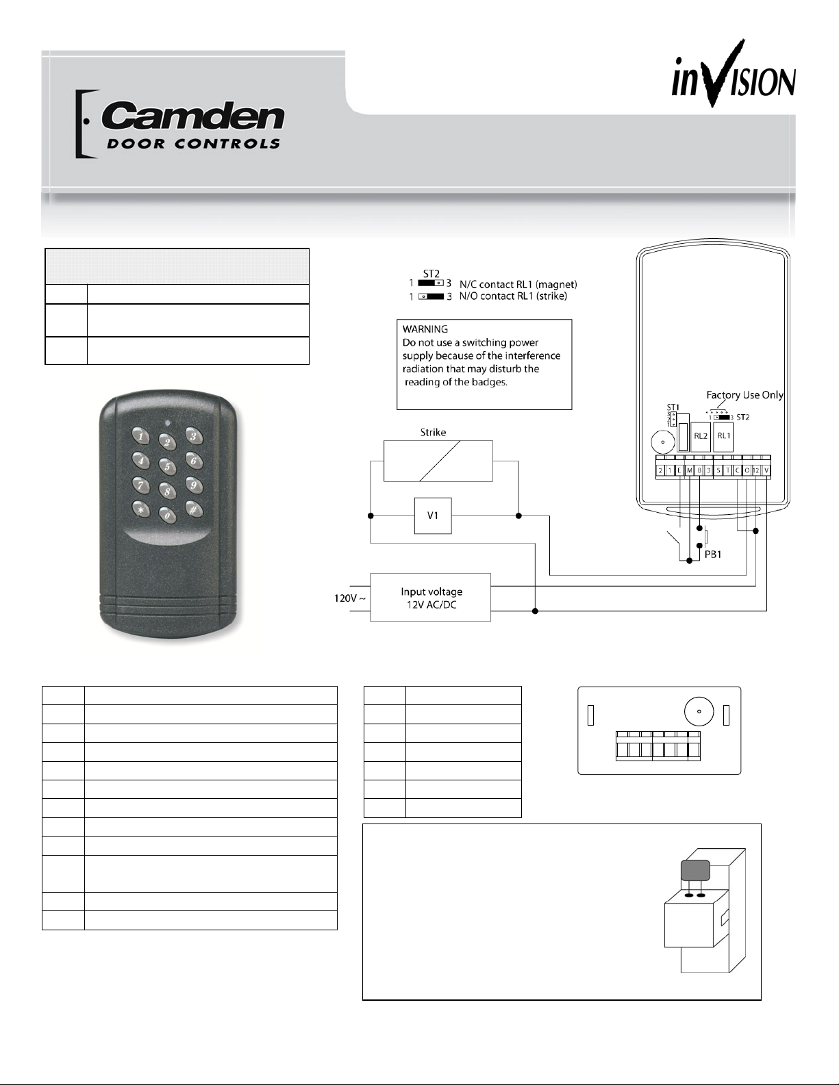
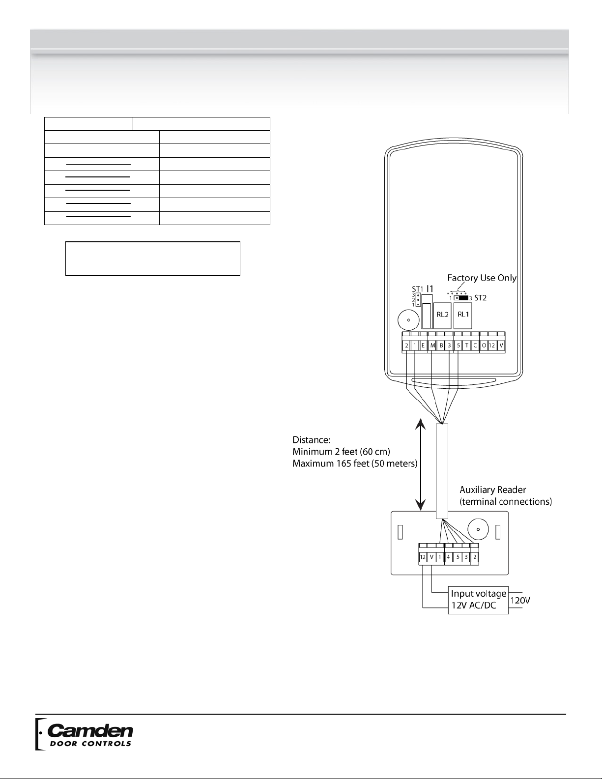
Input Voltage 12 V AC/DC
Output 2 relay outputs, N/O & N/C contact 3 A @ 125 V
Anti-Triggering Contact 500 mA 50 V AC/DC
Card 500 programmable cards or badges
PIN Code 500 programmable codes, 4-digit PIN code
Master Code 6-digit programmable code
Input 1 request-to-exit
Keyboard 12-digit keypad with built-in buzzer (audible signal)
Distance between the
second reader and the
CV-500PPK-V.2
Minimum 24 inches (60 cm)
Maximum 165 feet (50 meters)
(cable minimum requirement is 7 conductor 22 AWG)
Default Values
Master Code: 000000
Relay time release: 1 second
Key-in keypad: 10 seconds
Alarm: OFF
Audible Signals
1 beep (long) Validation of data in programming mode: master code, master card, user card or time delay.
Or authorized access card or Pin code.
2 beeps (long) Unauthorized access.
4 beeps (short) Incorrect mode, user number, time entered, data error.
6 beeps (long) Entering in programming mode.
Or exiting from the programming mode.
Visual Signals
LED Color Normal Mode Programming Mode
Green Door relay activated Code/Badge position empty
Green flashing Data computing validated
Red Alarm relay activated Code/Badge position busy
Red flashing Proximity badge validated
Orange flashing Stand-by Data computing error
Request-to-exit
The request-to-exit push button PB1 operates relay RL1.
The LED turns green when the relay is activated.
Warning:
Do not use a switching power supply because of radiation interference, which may disturb the reading of the badges.