CBE PC380-KT User manual

PC380-KT
USER’S MANUAL
NEW TECHNOLOGY
ELECTRONICS FOR CARAVANNING
EN
ed. 05/2020 cod. 000516 Rev.02


3
EN Main parts of the electrical system 4
C KT 5ONTROL PANEL “PC380- ”
A 4dvice and checks
Descriptions 5
Main visualizations 6
Users’s setting 8
DISTRIBUTION BOX “DS520-AN” 12
Functions 7
Protection fuses 12
Electrical system functions 15
Connections 13
INSTALLATION “PC380- ” KT 16

4
MAIN PARTS OF THE ELECTRICAL SYSTEM
> 520-AN12V DISTRIBUTION BOX “DS ” - main relays, battery parallel relays (12V - 70A), fridge relays, pump
relays, car battery recharging device, ampere meter, protection fuses.
> LEISURE BATTERY “B2” - it gives power to all users.
> ENGINE ALTERNATOR - it recharges in parallel both the chassis and the leisure battery.
> “ HASSIS50A” C (B1) AND LEISURE (B2) BATTERY PROTECTION FUSES.
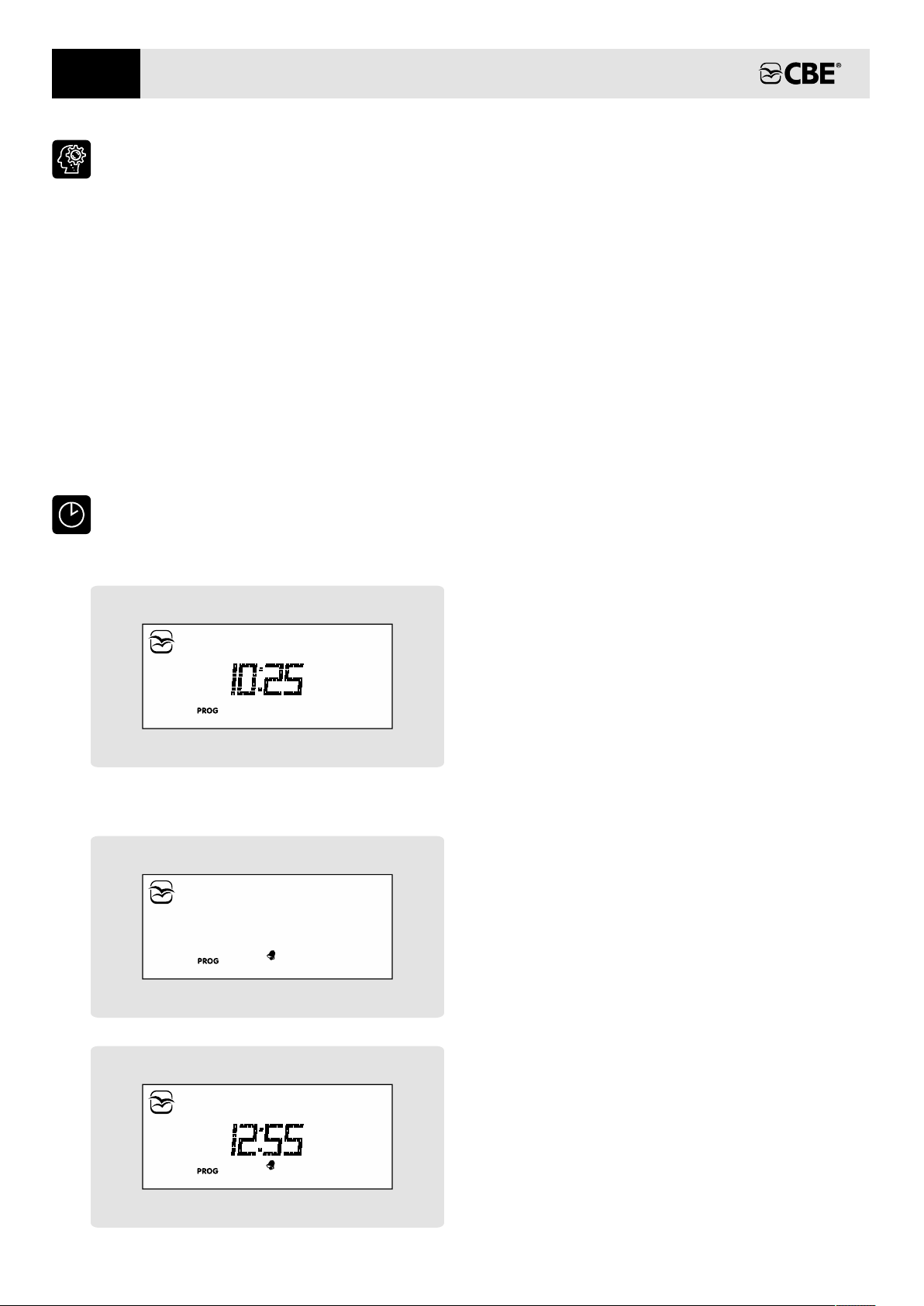
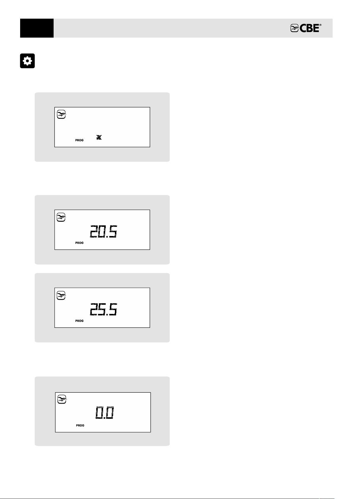
> “PC380-KT” CONTROL PANEL - mains’ control, battery test, tank test and clock function.
> BATTERY CHARGER - charge .supplies to batteries
> ELECTRONIC TANK PROBE - it measures the content of the water tankfresh and waste s.
> CHASSIS BATTERY “B1” - chassis power.
> 4 CIRCUIT BREAKER2 0V - it power and protects all users.switches
ADVICE AND CHECKS
BATTERIES
Check periodically the level of the liquid of the battery
(with acid); the GEL battery does not need any
maintenance but countinuous
recharging.
does require
The battery charger must be installed in a dry and
ventilated place.
I is
void
n case of battery charger’s misuse, the guarantee
and the manufacturer declines all responsibility
for damages to people and .property
C terminal heck the correct tightening of the
connection binding screw and ensure terminals are
clean.
Do not carry out any maintenance when the battery
charger is connected to the 2 0V 4 mains power
supply vents, the charger requires . Do not cover air
In case of a prolonged period, all batteries should be
disconnected or recharged regularly.
If the battery is completely discharged it needs
recharging for 10 hours. If discharged for more
than 8 weeks it may be damaged.
up to
BATTERY CHARGER
If the leisure battery is removed, isolate the positive
pole (in order to avoid short circuit during an
accidental car engine starting).
a
T a
qualified technician
he installation of this device must be carried out by
.
Read with care the instructions of use and
maintenance of the batteries.
T noushe acid kept in the batteries is poiso and
corrosive. Avoid any contact with skin and eyes.
appropriate ventilation.
B 4
mains circuit breaker
efore disconnecting the battery charger from 2 0V
power supply, turn the off.
Before taking off the cover, check that the 240V mains
power supply is disconnected.
In order to avoid damage to the circuit breaker, check
that the connections are tightened correctly.
TANK PROBES
I turn the off 4n order to power to the whole 2 0V
system, please that the 2 0V main ensure 4 circuit
breaker is in the (OFF) position.
C 4 power
supply
onnect and disconnect the external 2 0V
only when the main switch is off.
If the circuit breaker trips, ensure to find the problem
before turning the power back on.
IMPORTANT: maintenance on the electric equipment
must be carried out by a qualified technician. Before
carrying out maintenance, disconnect the battery and
the 240V mains power supply.
240V CIRCUIT BREAKER
FUSES
Never le water in the tanks for ave a prolonged period
of time, in order to avoid fouling, especially in the
waste water tank.
Replace the fuses after finding out the real cause of
the damage only.
W insphen the fuses are replaced ect the value of the
amperage established.
IMPORTANT Maintenance on the electric must be carried out by : equipment a qualified
technician , 4 mains
power supply
. Before carrying out maintenance disconnect the battery and the 2 0V
.
EN

5
CONTROL PANEL “PC380-KT”
DESCRIPTIONS
situation (see also the “TWILIGHT” function).
4) Button with integrated twilight sensor to set the
intensity of the LED backlighting in a night“ ”
5) On/off button (to turn on/off press for 2
seconds) at the start-up the display carries out
a functioning test and shows all symbols
(including unused symbols).
main
:
If the relevant LED is green the control panel is
on, if it is red an alarm is on (batteries, tanks,
etc.).
1)
«12V» b circuit
(lights and awning light).
utton to switch the light on and off
2) Button to switch the pump on and off.water
3) Awning e awning light button; th light switches
automatically off when you start up the engine
(it depends on the 12V button).
8) Button for control of c and leisure
batteries voltage (in Volt), load and recharge
current (in Ampere) for the leisure battery and
for the parameters’ setting (see SETTING).
hassis
clock willShould B2 be disconnected, the
keep working, without visualization, for
approx 1 week.
NOTE: The is supplied from the
leisure battery (B2).
digital clock power
7) Button for the control of fresh and waste water
tank (in %), for the information on the
programmable parameters’ setting (see
SETTING).
6) “PROG” button for system (see
SETTING).
setting
1 2 3 4
12 3 4
5 76 8
EN

6
MAIN VISUALIZATIONS
6) Internal temperature digital indicator.
7) Clock digital display.
1) . It indicates that the engine is on
8) It displays the setting menu.
2) It displays that the battery parallel is on when
engine is on.
5) External temperature digital indicator.
3) It displays that the chassis battery recharging
unit is on.
4) It indicates that the 2 0V battery charger is
on
4
.
16) It displays that the c battery has
run down.
hassis (B1)
9) It displays that the tones are off.
17) It displays that the leisure battery has run
down.
(B2)
15) It displays the minimum voltage device is on.
14) It displays that the waste water tank is full.
1 )2 “ ”B2 leisure battery status display.
10) It displays that alarm clock is set.
1 )1 Fresh water tank status display.
1 )3 It displays that the water tank is empty.fresh
21 3 4
6
5
7
89 10
12
11
13 14 15 16 17
EN

7
FUNCTIONS
CHASSIS BATTERY ALARM (B1)
Fuses
greater .
are automatically reactivated when voltage is
than 13 5V.
It is possible to reactivate all for one minute by
pressing the on/off button (ref. on control panel)
fuses
5 .
When the chassis battery voltage drops down to 12V,
the Chassis the
symbol ref. 16 starts blinking.
Battery Discharge alarm goes on and
MINIMUM VOLTAGE CONTROL (BATTERY
PROTECTION)
When the leisure battery voltage drops down to
10.5V, the eisure ischarge alarm
automatically , the symbol ref. 17 starts blinking
and you hear two short beeps. Alarms go off when the
voltage gets over 12.5V
L Battery D goes
on
.
LEISURE BATTERY ALARM (B2)
When leisure battery voltage drops down to 11.5V the
L Battery R goes on, eisure eserve alarm automatically
the symbol ref. 17 starts blinking and you hear a short
beep.
Alarm goes off when the voltage gets over 12.5V.
The electronic battery protection device cuts off the
12V when leisure battery reaches 10V and
disables: pump, lights, ,
fuses
awning light
and stove.
exit RH“ ”, TV
sockets
Symbol ref. 15 is the visual alarm signal.
The control panel automatically turns off with a
voltage lower than 9.5V.
This device doesn’t control the the 12V users
connected directly to the leisure battery B2 .
ment- Measure is carried out as difference
between charging and discharging currents: a
positive value indicates a charging current, a
negative value indicates a discharging current.
ment- Measure range is: -40A ÷ +40A.
- It measures the current of the leisure battery,
users’ consumption and recharge through
battery charger, engine alternator and solar
panels.
The ammet er is inside the DS520 AN module.-
AMMETER
To measure the charging of a sole source (battery
charger, alternator or solar panels), turn off all
items and other charging sources.
An electronic device switches off the awning light
when engine is turned on.
To measure the consumption of a sole user,
disconnect all charging sources and turn off all
unused items.
AWNING LIGHT AUTOMATIC TURN OFF
DIGITAL CLOCK
ALARM CLOCK
To set and activate/deactivate the alarm clock see
“SETTING”.
To reset alarm press any test button; there is no
delayed alarm!
To set clock see “SETTING”.
TEMPERATURE
- Both int. and ext. temperatures have a sensor, which
is placed inside or outside of the vehicle.
TWILIGHT FUNCTION
NOTE: before replacing the fuse find out the problem
that determined the intervention of the protection
(blown fuse) it may be necessary to have a
qualified technician assist
and fix it,
.
The lighting of the LED signals that the fuse is broken
and it is necessary to replace it with another fuse with
the same value. The alarm is activated only when the
control panel is on and the user related to the fuse is
switched on.
- The precision of the temperature value is ±1°C.
Under each fuse is positioned a red LED.
In a “night” situation, a sensor positioned near the
display causes the intensity of the LED backlight to
automatically be reduced to the level preset by the
user (to set see SETTING).
BROKEN FUSE ALARM
EN

8
USER’S SETTING
- by selecting “ ” you operate the menu to set CLOCK
sSelect, by pushing the arrow keys ref. 7 and 8, the
setting menu you want to operate and then
confirm by pushing the PROG button 6 ; “ ” (ref. )
the parameters clock and alarm clock
- by selecting “DISPLAY” you operate the menu to
set the display parameters.
sTo enter the set mode, press the PROG” button
(ref. ) for more than 2 seconds
“
6 from the main
clock screen.
- by selecting “SETTING” you operate the menu to
set the system parameters .
sTo exit without saving wait 20 seconds without
pressing any key.
sBy using the arrow keys ref. 7 and 8 you can
modify the setting of the parameters.
sTo abandon programming and save changes,
select “EXIT” and then choose to save or not save
changes.
sConfirm the setting by pushing “the PROG” button
(ref. )6 , you then go automatically to next
parameter.
CLOCK MENU
CLOCK
Clock setting:
- HOURS (blinking)
- MINUTES (blinking)
ALARM CLOCK
- ON (a )ctivation
- OFF (deactivation)
Activation of alarm clock:
- MINUTES (blinking)
Set alarm clock time (only if alarm clock has been
previously activated):
- HOURS (blinking)
clock
alm.clock
ON
alm.clock
EN

9
BUTTONS BACKLIGHT SETTING
Intensity setting of the buttons LED backlight in a
- (0÷100 %)
“night” situation (see also the “TWILIGHT” function) :
DISPLAY
%
DISPLAY BACKLIGHT SETTING
Display’s backlight setting when control panel is in
- (0÷100 %)
stand-by:
%
DISPLAY BACKLIGHT COLOUR
Display backlight colour selection
DISPLAY CONTRAST
D contrast setting 0 ):
isplay (0÷10 %
0 )(0÷10 %
COLOUR
CONTRAST
%
EN

10
SETTING
ACOUSTIC ALARMS
- ON (activation)
- OFF (deactivation)
Activation/Deactivation of acoustic alarms:
TEMPERATURES
Setting internal temperature, step 0.5°C
Setting external temperature, step 0.5°C
CALIBRATION AMMETER
Calibration of 0 in ammeter (A).« »
Setting steps: 0.1A.
tones
ON
INT. TEMP.
+
EXT. TEMP.
+
EN
0 AMP
+

11
Setting of the car battery “B1” voltmeter.
Max. value +/- 0.5V, step 0.1V.
b1 set
V
SMITTER
Activation/Deactivation visualization in bars of the
leisure battery and fresh water tank status in the
starting page.
- ON (activation)
- OFF (deactivation)
SmITTER
ON
EN
VOLTMETERS SETTING
Setting of the leisure battery “B2” voltmeter.
Max. value +/- 0.5V, step 0.1V.
b2 set
V

12
DISTRIBUITION BOX “DS520-AN”
PROTECTION FUSES
14) 20A fuse lights “B”for circuit .
16) AES fridge connection; It is a bridge, which
excludes the 3 way function fridge and is used to
connect the AES fridge directly to the B2.
12) 10A fuse the water pumpfor .
10) 3A fuse spark ignitions for for the fridge, oven &
stove, it is connected directly to the leisure
battery (B2).
11) Not actived.
17) Output + for the control of the auxiliary relays
(e.g. motorized step, AES fridge, electric water
discharge valve, electric antenna motor, etc.)
which works only when the engine is started.
13) 20A fuse lights “A”for circuit .
15) 3A fuse from ignition to protect the OUT D+
simulated exit.
2) 3A .Spare
3) 15A fuse the RH auxiliary for roof fans etc (if
fitted).
4) 20A TV socketsfuse for and TV antenna (if
fitted).
5) 15A fuse the RH auxiliary 2for range hood and
water pump switch (if fitted).
nd
6) 30A fuse 12V fridgefor element (when
connected through bridge 16 it turns off
automatically when engine is off).
1) 5A fuse to give power the AUX auxiliary exit
( )awning light , turns automatically off when
engine is on.
8) 20A fuse AUX for the (i.e. Gas detector, radio
memory etc), it is connected directly to the
leisure battery (B2). (constant supply)
9) 25A fuse motorized step , it is
connected directly to the leisure battery (B2).
for the (if fitted)
7) 10A fuse for Heater/Hot Water System (HWS).
1 2 1 2
8
9
1 10
2 11
3 125 147
4 136 15
-B2 +B2 + OUT 12V
1 2 3 4
1 2 3 4 1
9
8
16
28
20 21
16
19
24
25
31
30
29
+B1
32
17
12
26A 26B
27
22
1 2
23
1
4
3
2
18
RE-VI
RE-EL
POT
EN

13
SIGNALS (OPTION A )“ ”
2) + input signal “S” net coming from the CBE battery charger.
1) + input signal contact key engine starting.
SIGNALS (OPTION “B”)
1) - input “D+” negative signal (-)
2 ) + input signal contact key engine starting.
1) + input signal “S” net coming from the CBE battery charger.
2 /)
1
2
1
2
26B)
27)
NOT CONNECTED
23)
USERS
1) + exit heater/HWS, it depends on the main button
ON/OFF.
3) /
7-8-9) + exit lights "B”circuit ; it depends on button.12V
2) + exit water pump; it depends on the pump button.
4 circuit ; -5-6) + exit lights "A" it depends on button.12V
FUSIBILE
12
13
11
7
14
21)
147
25 8
3 6 9
USERS
19)
14
25
36
3) + exit AUX (awning light), awning lightit depends on the
button.
2) + exit spare, it depends on the main button ON/OFF.
6) + exit RH, it depends on the main button ON/OFF.
1) + exit RH, it depends on the main button ON/OFF.
4-5) + exit TV sockets, it depends on the main button ON/OFF.
FUSE
3
1
5
2
4
24)
FRESH (POT) WATER TANK
To connect to the water tank probe.fresh
22)
USERS
5-6-8-9) exit gas users (fridge, k , ecc ...) (direct “B2”)itchen
2-3) + exit 3 way function fridge / AES
4) + exit electric step (direct “B2”)
1) + exit AUX (direct “B2”)
FUSE
8
6
9
10
20)
147
25 8
3 6 9
NOT CONNECT
18)
EN
CONNECTIONS
1 2
26A)
1
9
8
16
CONTROL PANEL
To connect to the 16 poles connector of the control panel.
25)
WASTE WATER TANK PROBE WITH SCREWS (RE-VI)
To connect to the waste water tank probe with screws or to the electronic
waste water tank probe.
NB: Do not connect both types of tank probes!
ELECTRONIC WASTE WATER TANK PROBE (RE-EL)

14
EARTH
To connect to the mains' earth.
28)
EARTH
To connect to the negative pole of the battery or to the chassis of the
vehicle.
leisure
29)
LEISURE BATTERY
To connect to the pole of the batterypositive leisure .
30)
12V EXIT
To connect to the positive pole (battery charger, solar regulator).
31)
+ OUT 12V
+ B2
- B2
CHASSIS BATTERY
To connect to the positive pole of the chassis battery.
32)
+ B1
EN

15
EN
ELECTRICAL SYSTEM FUNCTIONS
a) alternator: Throught engine
b) : Throught 240V mains power
Operation without SMART ALTERNATOR:
When the battery charger is charging, an electronic
device allows a recharging ( A) of
the c battery (B1), the system gives priority to
the leisure battery (B2).
nominal current 2
hassis
through separate relays when engine is on.
The ignition electronically controls the relays:
parallel, fride, awning light etc.
An electronic device controlled by the “+ key” ON
switches on the D+ functions (batteries parallel, OUT
D+ simulated output, awning light etc.) when the car
battery voltage is > 13.5V and switches them off with
the “+ key” OFF or with voltage < 12.5V.
D+ FUNCTIONS
CHASSIS BATTERY (B1) RECHARGING
mains power throught battery charger.
The D+ functions can be activated only if the B2
leisure battery is connected.
LEISURE BATTERY (B2) RECHARGING
c) solar panel: through solar
regulator.
Throught charge Condition B: with “+ key” ON signal and “D+”
negative signal (-). The functions are
deactivated in absence of one of
those two signals.
Operation with SMART ALTERNATOR (present on
all DS distribution boxes manufactured since
September 2019)
520
:
Condition A: with “+ key” ON signal and car battery
voltage > 13,5V. The functions are
deactivated with “+ key” OFF or with
voltage < 12,5V.
For vehicles equipped with SMART ALTERNATOR
n electronic device switches on the D+ functions
(batteries parallel, OUT D+ simulated output, awning
light etc.) when the engine is running. The D+
functions are activated in presence of at least one of
following conditions:
,
a
The D+ functions can be activated only if the B2
leisure battery is connected.
N.B.: In presence of both conditions, the functions
are deactivated in absence of the “+ key” signal.
IMPORTANT in the case of installation of equipment that needs permanent exclusion of the battery parallel
relay (ref. 1), you must remove the R resistor (ref. 2). The resistor can be removed using a wire cutter,
being careful not to damage the PCB traces below.
:
72
This resistor is 520
Juny 2020.
present on all DS distribution boxes
manufactured since
1
2

16
INSTALLATION “PC380-KT”

17
NOTE

18
NOTE

19
NOTE

20
CBE S.r.l.
Via Vienna 4 z.i. Spini (settore D)
121 Trento
, -
38 - Italy
Tel. +39 0461 991598
Fax +39 0461 960009
www.cbe.it
ELECTRONICS FOR CARAVANNING
Table of contents
Other CBE Control Panel manuals