9
www.cdvi.com
www.cdvigroup.com
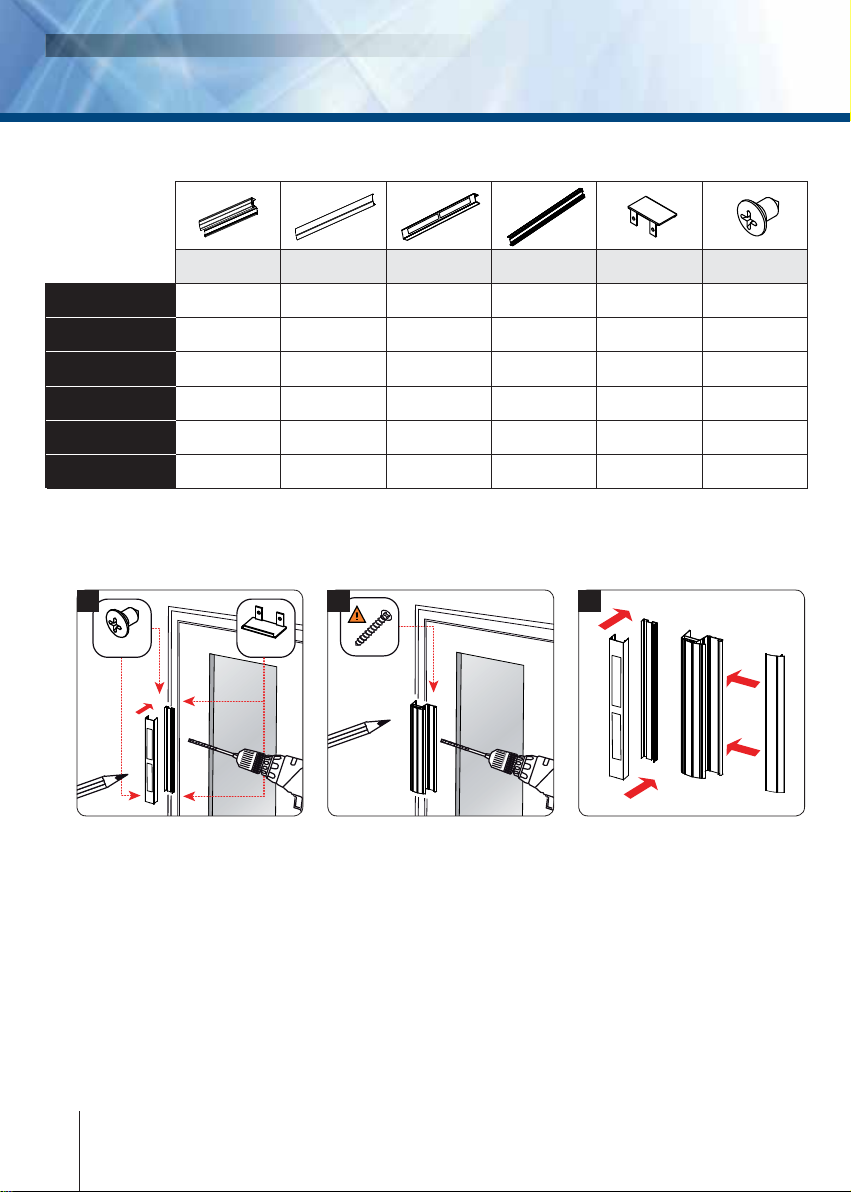
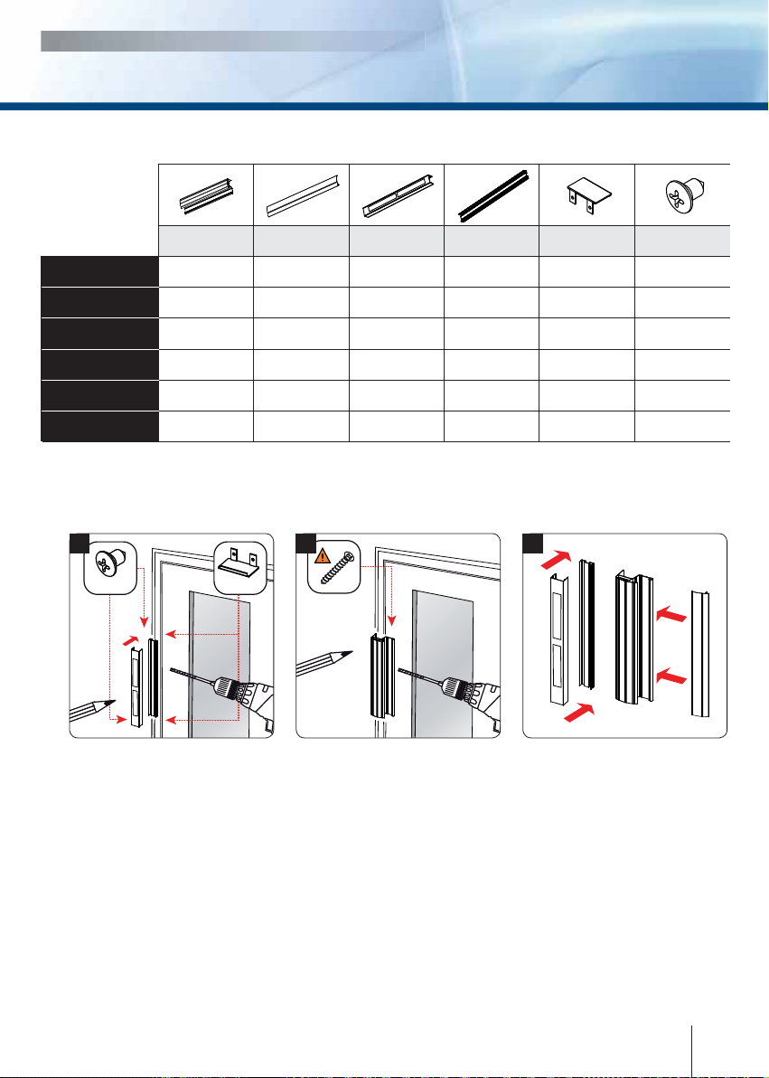
1 2 3
4] MONTAGE
Avant de commencer le montage, réunissez les outils nécessaires (Perceuse, visseuse,
mètre, tournevis, vis, chevilles, écrous…), en fonction de la surface d’installation.
Positionnez le support mural avec
ses ventouses sur le fixe ou semi
fixe. Prenez les marques dans les
trous oblongs horizontaux et verti-
caux et percez la surface du vantail
auniveaudesmarques.Prévoyezles
sorties des câbles grâce au bos-
sage central à l’arrière du support
mural et en vous aidant du schéma
de câblage des ventouses (page
suivante). Vissez le support mu-
ral et fixez les bouchons à chaque
extrémité du profil à l’aide des vis
auto-taraudeuses à tête bombée
M4 (fournies).
Positionnez la poignée bandeau
munie de ses contre plaques sur
le vantail ouvrant. Prenez les mar-
ques dans les trous oblongs hori-
zontaux et verticaux pour fixer la
poignée bandeau. Percer la surface
de la porte au niveau des marques
réalisées. Placez et vissez provisoi-
rement la poignée afin de laisser
un léger espace qui vous permettra
d’effectuer le réglage final de l’en-
semble. Fermez la porte, vérifiez
que les ventouses sont bien posi-
tionnées face à leur contre plaques
puis fixez définitivement la poi-
gnée bandeau.
Pour finaliser le montage, position-
nez
le capot sur le support mural
et emboitez-le dans son logement.
Il est aussi possible de visser le
capot par ses extrémités à l’aide
de vis auto taraudeuse (tête fraisée
M2) directement sur le support
mural. Pour le bandeau, même
procédure, installez le cache vis
dans sa charnière et emboitez-le
dans son logement.
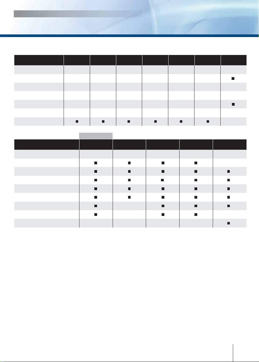
3] KIT DE MONTAGE
Vis M4x6 à
tête bombée
Bouchons
casquette
2
2
2
2
2
2
4
4
4
4
4
4
Profil support
mural
1
1
1
1
1
1
Profil poignée
avec bouchons
Profil
cache-vis Capot pour
support mural
BO800RN (2,5 m)
BO1200RN (2,5 m)
BO800RN (3 m)
BO1200RN (3 m)
PBO800RN (60 cm)
PBO400RN (40 cm)
1
1
1
1
1
1
1
1
1
1
1
1
1
1
1
1
1
1
BO800RN
Bandeaux architecturaux et poignées ventouses
INSTALLATION MANUAL