manuals.online logo
Brands
  1. Home
  2. •
  3. Brands
  4. •
  5. Checchi & Magli
  6. •
  7. Farm Equipment
  8. •
  9. Checchi & Magli 998963 User manual

Checchi & Magli 998963 User manual

1
Use and Maintenance Manual
Code: 998963/4
Edition: 08/2018
Language: English
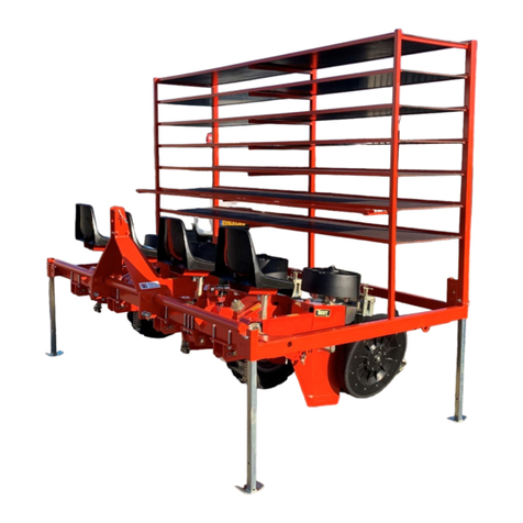
TRAILER WITH WATER TANK
2
ILLUSTRATION OF FRAME PARTS
1. Fixed frame
2. Lift
3. Unit carrier frame
4. Tray storage
5. Platforms
6. Water barrels
7. Oil inserts
8. Water system
9. Water level
10.Oil diverter
11.Vent pipe
1
2
4
3
5
6
8
7
9
11
10
3
INDEX
1. WARRANTY Pag. 6
2. INTRODUCTION Pag. 6
3. TECHNICAL DATA Pag. 6
4. WARNING AND DANGER SIGNS Pag. 8
5. LIFTING Pag. 9
6. MOUNTING THE TOWBAR Pag. 10
7. ATTACHING AND DETACHING THE UNIT CARRIER
FRAME Pag.10
8. TRACK ADJUSTMENT Pag. 12
9. LIFT SPEED ADJUSTMENT Pag. 12
10. HYDRAULIC CYLINDER ADJUSTMENT Pag. 13
11. TRANSPORT Pag. 14
12. REQUIREMENTS FOR SAFE USE AND ACCIDENT
PREVENTION Pag. 14
13. LOADING WATER Pag. 15
14. FUNCTIONS OF THE TRACTOR DRIVER Pag. 16
15. ATTACHING AND DETACHNING THE TOWING
FROM THE TRACTOR Pag. 16
16. MAINTENANCE Pag. 17
17. SEASONAL STOPS Pag. 17
18. DISPOSAL Pag. 18
19. SPARE PARTS Pag. 18
4
5
6
1. WARRANTY
Check on delivery that the machine and accessories are intact and
complete.
Any complaints should be submitted in written form within eight days of
receipt.
WARRANTY EXPIRY
The warranty is void if the instructions described in this manual are not
complied with.
2. INTRODUCTION
This manual describes the rules of use and maintenance and the spare
parts relative to the hydraulic towing frame.
This frame can function only if it is attached to a tractor equipped with a
universal coupling and with one or two operators on board at each
transplanting unit.
It is recommended to observe what is described in this manual, as it
will function correctly only with the correct use and maintenance.
Improper use of the instructions may cause inconveniences and affect its
correct functioning and duration.
The Manufacturer declines any and all liability due to negligence and
failure to comply with these instructions.
In case of dispute the Italian reference text remains valid.
For any dispute the competent Court is Bologna.
3. TECHNICAL DATA
·Frame weight with one barrel (without driving wheels,
transplantation unit and empty barrel) Kg.625 - Lb.1389
·Frame weight with one barrel(with driving wheels, transplantation
unit and full barrel) Kg.2035 - Lb.4522
·Frame weight with two barrels (without driving wheels,
transplantation unit and empty barrels) Kg.850 –Lb.1889
·Frame weight with two barrels (with driving wheels,
transplantation unit and full barrels) Kg.2780 –Lb.6178
·Maximum water barrel capacity Lt.1000 –Usa gal.264
·Hydraulic system work pressure Bar 150-200
·Pneumatic pressure of towing frame Bar 5.5
·Minimum track Cm.200- Inches 78-3/4
·Maximum track Cm.240- Inches 94-1/2
·Dimensions of towing frames (without driving wheels and
transplantation unit)
7
Frame towed with one barrel
Frame towed with two barrels
8
4. WARNING AND DANGER SIGNS
Warning signs:
1-Before starting work carefully read the instruction booklet.
2-Before any maintenance work, stop the machine and consult the use and
maintenance manual.
Danger signs:
3-Do not make any movements on the work field and on the road with
operators on board.
Indication signs:
4-Coupling point for lifting
5-Greasing points
1
2
3
4
5
9
5. LIFTING
5.1-Check that the lifting means, hooks, ropes, chains etc…. have the
necessary capacity.
5.2- Check that the unit carrier frame is detached (see detaching unit
carrier frame page 8).
5.3-Check that the water barrels are completely empty.
5.4-Fix hooks, ropes, chains etc…“A”in the positions indicated in Fig.1 on
page 7 (to lift the towing frame with one barrel) and Fig.2 on page 7 (to lift
the towing frame with two barrels), marked with the graphic symbol
“HOOK”.
5.5-Slowly start the lifting system and before lifting totally, check the
stability of the load and that there are no extraneous persons in the area.
5.6-Keep a safe distance and do not go, for any reason, in an area where
there is the risk of the machine falling.
WARNING! The lifting hook “B”of the water barrels in Fig.1 and Fig.2 can only be
used to lift one water barrel and only when it is completely empty.
Fig.2
Fig.1
2
A
A
A
A
B
A
C
10
6. MOUNTING THE TOWBAR
Proceed as follows to mount the tow bar:
6.1-Insert the tow bar Aonto the fixed frame as illustrated in the picture.
6.2-Fasten it onto the frame by using screws Band bolts C.
7. ATTACHING AND DETACHING THE UNIT CARRIER FRAME
Proceed as follows to attach the unit carrier frame:
7.1-The tractor must be switched off with the service brake on.
7.2-The tractor must be on solid and level ground.
7.3-Check that the tow bar is fixed properly onto the fixed frame (see
mounting the tow bar).
7.4-Move the tractor closer and attach it to the fixed frame with the tow bar.
7.5-Mount pivots “A”and ball joints “B”in the upper hole as shown in Fig.3
(Warning! Check that spacer “C”is positioned as in Fig.3).
7.6-Attach the oil inserts of the towing frame to the appropriate inserts
present on the tractor.
7.7-Connect the unit carrier frame to the lift of the towing frame by
mounting tie rod “D”inserting pivots “E”, block quick couplings “F”Fig.4
7.8-Lift supporting foot “G”.
Proceed as follows to detach the unit carrier frame:
7.1.1-The tractor must be switched off with the service brake on.
7.1.2-The tractor must be on solid and level ground.
7.1.3-Bring the tractor close and by using the tow bar, connect it onto the
fixed frame.
7.1.4-Lower supporting foot “G”.
7.1.5-Lower unit carrier frame.
7.1.6-Remove the pivot “E”, unblock the quick couplings “F”.
A
B
B
C
C
11
E
Fig.3
2
Fig.4
2
G
C
B
A
E
D
E
F
C
B
A
12
8. TRACK ADJUSTMENT
Proceed as follows to adjust the track:
8.1-The tractor must be switched off with the service brake on.
8.2-The tractor must be on solid and level ground.
8.3-Check that the water barrels are completely empty.
8.4-Detach the unit carrier frame (see detaching unit frame).
8.5-Hook ropes and chains onto the frame (see lifting the frame).
8.6-Lift the frame off the ground as less as possible to be able to detach
the tow bar from the tractor.
8.7-Lift the frame as needed to be able to attach the appropriate devices
(support stand etc.) to keep the frame lifted safely from the ground.
WARNING! Do not go under the lifted machine if it is not properly
blocked.
8.8-Loosen the nuts “C”Fig.2 page 7 and adjust the wheels fixed to the
axles in a transversal manner until you reach the desired track.
8.9-Tighten the nuts “C”.
9. ADJUSTING THE LIFT DESCENT SPEED
Based on the load applied to the lift, it is possible to increase or
decrease the descent and ascent of the lift, proceed as follows:
9.1-Loosen locknut “B”that blocks valve rotation “A”.
9.2-Turn valve “A”clockwise/anti-clockwise to increase/decrease the
ascent and descent speed of the lift.
A
B
13
10. HYDRAULIC CYLINDER ADJUSTMENT
The hydraulic cylinder can be adjusted in a manner to always ensure
correct transplantation, even in the presence of No Till, acting only on the
special diverter.
For machines without No Till, adjust the cylinder as described:
1- Make sure the unit carrier frame is lifted so the cylinder is in the position
shown in figure “7”;
2- Make sure vent pipe “A”is positioned towards the ground as shown in
the figure;
3- Unscrew pommel “B”and put lever “C”in the Normal Use position as
shown in figure 6;
4- Screw the pommel
The cylinder will work normally in this manner.
For machines with No Till, adjust the cylinder as described:
1- Make sure the unit carrier frame is lifted so the cylinder is in the position
shown in figure “7”;
2- Make sure vent pipe “A”is positioned towards the ground as shown in
the figure;
3- Unscrew pommel “B”and put lever “C”in the Normal Use position as
shown in figure 6;
4- Screw the pommel
In this manner the cylinder will keep the unit carrier frame locked
downwards, avoiding lifting due to No Till.
Warning! In the event the cylinder is positioned incorrectly, all the
remaining oil inside it will come out of the vent pipe whenthe unit carrier
frame is lifted.
2
1
A
C
B
A
14
Fig.6 Fig.7
11. TRANSPORT
Check that the vehicle to be used is suitable in terms of capacity,
dimension and anything else foreseen by the Highway Code.
Position the machine, avoiding non-standard protrusions and secure it
properly with ropes or other equipment to avoid uncontrolled movements.
12. REQUIREMENTS FOR SAFE USE AND ACCIDENT
PREVENTION
Carefully read all the instructions before using the machine,
especially to protect physical safety.
The Manufacturer declines any liability for any damage resulting from
improper use of the machine, or failure to comply with these instructions.
The user must inform employees and collaborators of the indications in
this manual (it is an obligation established by law).
Pay attention to danger signs illustrated in this manual and on the
machine.
Technical interventions, adjustments and maintenance must be carried out
only when the engine is off, with the machine on the ground, arms
lowered and tractor blocked (service brake on).
Hook the machine only onto a suitably powered tractor (see technical card
with reference to the model in use).
Respect the maximum weight on the axle and the total mobile weight.
During the attaching and detaching phases of the machine, pay strict
attention to avoid crushing.
It is strictly forbidden to drive or let people drive who do not have a licence,
are unskilled or unhealthy.
When the tractor is running, never leave the driving seat.
Before leaving the tractor, lower the rear unit carrier frame, turn off the
engine, put on the service brake and remove the key from the control
panel. Keep in mind that road holding, direction capacity and braking are
influenced by the presence of a driven or towed machine.
15
To circulate on the road, you must comply with the Highway Code in force
in the relative country.
During transportation on the road, put the command lever of the hydraulic
cylinder in the locked position with the unit carrier frame raised.
Operators must be seated with their feet on the footboards, only with the
tractor stationary and locked and with the machine placed on the
ground.
It is strictly forbidden to make any movements on the work field and
on the road with operators on board.
It is forbidden to get off the machine when in movement and not positioned
on the ground.
The movement apparatus (wheels –chains –distributors –etc…) are
protected by covers and where it is not reasonably possible, a sufficient
space is provided to not incur in crushing.
Totally avoid using flowing clothes which can get caught up in the
above mentioned apparatus during functioning, and however pay strict
attention during work as the apparatus is always moving.
Do not remove safety and protection devices which have been installed.
If they are removed for adjustments or maintenance, make sure they are
put back into place.
Frequently check the efficiency of the protection devices and replace them
when necessary, using only original spare parts, that can be supplied by
the Manufacturer or by its authorized dealers.
Do not let unskilled persons use the machine; in the case of accidents
you may be personally held responsible.
It is strictly forbidden to raise or lower the unit carrier frame with
operators on board.
Check that during lifting or lowering operations of the element carrier
frame that persons who are not involved in the operations are at a
safe distance.
13. LOADING WATER
Proceed as follows to fill the water barrels:
13.1- Make sure that the unit carrier frame is in a horizontal position
compared to the ground (see Fig.5 page 14).
The tractor must be switched off with the service brake on.
The tractor must be on solid and level ground.
No one must use and/or tamper with the hydraulic commands.
13.2- Approach the barrels by using only the platforms Fig.5 page 14.
13.3-Unscrew the barrel cover and fill to the maximum capacity.
16
14. FUNCTIONS OF THE TRACTOR DRIVER
Comply especially with the safety rules indicated in this manual.
Agree on voice commands for starting and stopping with the operator/s
before starting work.
Adjust the requested speed by using the gearbox ratios, maintaining the
lowest engine speed possible.
Make sure that the exhaust gasses are not in the direction of the operators
and that the silencer is in perfect working condition.
Complying with the above allows you to work with limited noise, facilitating
the understanding between the operator and the tractor driver.
It is preferable to lower the transplanter while moving forward slowly to
minimize the accidental entry of soil in the ploughshares.
Avoid reversing with the transplanter still positioned on the ground.
Check that all operators are off the machine before lifting the unit
carrier frame.
15. ATTACHING AND DETACHING THE TOWING FRAME FROM
THE TRACTOR
Proceed as follows to attach the towing frame:
Move the tractor close to the towing frame.
The tractor must be switched off with the service brake on.
The tractor must be on solid and level ground, without any risks.
Check that the water barrels are completely empty.
Secure the tow bar onto the tractor with the pivot.
Attach the oil inserts to the tractor.
Fig.5
UNIT
CARRIER
FRAME
PLATFORM
COVER
17
Proceed as follows to detach the towing frame:
The tractor must be switched off with the service brake on.
The tractor must be on solid and level ground, without any risks.
No one must use and/or tamper with the hydraulic commands.
Check that the water barrels are completely empty.
Lower the unit carrier frame until the transplantation unit is completely on
the ground.
Lower the support stand that is fixed onto the tow bar.
Detach the oil inserts.
Detach the towing frame from the tractor.
16. MAINTENANCE
The following technical intervention times are approximate for normal
conditions of use.
In the case of more severe service conditions, due to the environment or
seasonal factors, maintenance interventions must logically increase.
Intervene only by complying with the safety requirements listed in this
manual.
EVERY 8 WORKING HOURS:
Check the lifting of the unit carrier frame.
Check warning and danger signs.
EVERY 50 WORKING HOURS
Check tightening of screws
Grease cylinder pivots.
Grease arm pivots.
Grease tractor arms.
EACH 150 WORKING HOURS
Check tyre pressure.
RECOMMENDED LUBRICANTS
Grease or oil that is used for the tractor may be used, respecting the
warnings and precautions indicated on the relative containers.
17. SEASONAL STOPS
At the end of the season or in cases of a one or two month stop it is
recommended: to wash the equipment, above all from any fertilizers or
chemical products, and dry it.
Check and replace any damaged or worn parts.
Carry out accurate greasing and protect the equipment with a sheet,
placing it in a dry place.
Apply a light layer of lubricant in the parts which are not protected from
galvanization or paint.
Position the equipment as indicated in the “Attaching and detaching of the
towing frame”paragraph.
18
18. DISPOSAL
The frame is composed of ferrous material and rubber wheels.
At the end of the operating cycle, it must be scrapped at the respective
authorized disposer.
19. SPARE PARTS
Ordering spare parts must be preferably transmitted by a Dealer and
supplied with the following indications:
Model type and serial number indicated on the applied plate;
Code number and description taken from the spare parts catalogue;
Required quantity;
Shipping is carried out in accordance with customer requirements.in the
absence of which will be carried out with the means considered most
suitable;
The term right or left is understood by looking at the machine from the rear.
19
20

This manual suits for next models

1

Other Checchi & Magli Farm Equipment manuals
Checchi & Magli PLASTIC-STOP PLUS User manual

Checchi & Magli

Checchi & Magli PLASTIC-STOP PLUS User manual

Checchi & Magli UNITRIUM User manual

Checchi & Magli

Checchi & Magli UNITRIUM User manual

Checchi & Magli BABY TRIUM User manual

Checchi & Magli

Checchi & Magli BABY TRIUM User manual

Checchi & Magli WOLF COMPACT/3 User manual

Checchi & Magli

Checchi & Magli WOLF COMPACT/3 User manual

Checchi & Magli BABY COMPACT User manual

Checchi & Magli

Checchi & Magli BABY COMPACT User manual

Checchi & Magli VR76 User manual

Checchi & Magli

Checchi & Magli VR76 User manual

Checchi & Magli DUAL 12 GOLD User manual

Checchi & Magli

Checchi & Magli DUAL 12 GOLD User manual

Checchi & Magli TRIUM Operating instructions

Checchi & Magli

Checchi & Magli TRIUM Operating instructions

Checchi & Magli WOLF User manual

Checchi & Magli

Checchi & Magli WOLF User manual

Checchi & Magli DUAL 12 GOLD User manual

Checchi & Magli

Checchi & Magli DUAL 12 GOLD User manual

Checchi & Magli FOXDRIVE-R14 DT User manual

Checchi & Magli

Checchi & Magli FOXDRIVE-R14 DT User manual

Checchi & Magli UNITRIUM User manual

Checchi & Magli

Checchi & Magli UNITRIUM User manual

Checchi & Magli SP50 User manual

Checchi & Magli

Checchi & Magli SP50 User manual

Checchi & Magli SP 150 onion User manual

Checchi & Magli

Checchi & Magli SP 150 onion User manual

Checchi & Magli FOX DRIVE PLUS User manual

Checchi & Magli

Checchi & Magli FOX DRIVE PLUS User manual

Checchi & Magli BABY COMPACT User manual

Checchi & Magli

Checchi & Magli BABY COMPACT User manual

Checchi & Magli WOLF PRO User manual

Checchi & Magli

Checchi & Magli WOLF PRO User manual

Checchi & Magli TRIUM 1 User manual

Checchi & Magli

Checchi & Magli TRIUM 1 User manual

Checchi & Magli WOLF PRO User manual

Checchi & Magli

Checchi & Magli WOLF PRO User manual

Checchi & Magli TOP 24 User manual

Checchi & Magli

Checchi & Magli TOP 24 User manual

Checchi & Magli TEXDRIVE BEST User manual

Checchi & Magli

Checchi & Magli TEXDRIVE BEST User manual

Checchi & Magli UNIFOX User manual

Checchi & Magli

Checchi & Magli UNIFOX User manual

Checchi & Magli TOP 24 User manual

Checchi & Magli

Checchi & Magli TOP 24 User manual

Checchi & Magli TEXDRIVE User manual

Checchi & Magli

Checchi & Magli TEXDRIVE User manual

Popular Farm Equipment manuals by other brands

Kverneland Vicon Andex 724 operating manual

Kverneland

Kverneland Vicon Andex 724 operating manual

Monosem NG Plus 4 Assembly, Adjustment and Maintenance Instructions

Monosem

Monosem NG Plus 4 Assembly, Adjustment and Maintenance Instructions

Vivo BEE-V002C instruction manual

Vivo

Vivo BEE-V002C instruction manual

Ovlac XPERIENCE manual

Ovlac

Ovlac XPERIENCE manual

Field Tuff Tuff FTF-063PTSD owner's manual

Field Tuff

Field Tuff Tuff FTF-063PTSD owner's manual

GREAT PLAINS 8321DV FIELD ADJUSTMENT GUIDE

GREAT PLAINS

GREAT PLAINS 8321DV FIELD ADJUSTMENT GUIDE

Ovlac MINI-BF Instruction manual and spare parts list

Ovlac

Ovlac MINI-BF Instruction manual and spare parts list

micronAir MICROMISER 12 Operator's handbook

micronAir

micronAir MICROMISER 12 Operator's handbook

Brinsea Chick Safe eco Installation and operating instructions

Brinsea

Brinsea Chick Safe eco Installation and operating instructions

horsch Avatar SD 40 quick start guide

horsch

horsch Avatar SD 40 quick start guide

Chapman AH200 instructions

Chapman

Chapman AH200 instructions

Degelman ROCK DIGGER RD320 Operator's & parts manual

Degelman

Degelman ROCK DIGGER RD320 Operator's & parts manual

Vivo BEE-V004E instruction manual

Vivo

Vivo BEE-V004E instruction manual

Horizont Agrar ranger A70 operating instructions

Horizont Agrar

Horizont Agrar ranger A70 operating instructions

Gaspardo PA1 Use and maintenance

Gaspardo

Gaspardo PA1 Use and maintenance

Stara 14000 TRAILER Instructions and parts manual

Stara

Stara 14000 TRAILER Instructions and parts manual

Headsight Truesight Remote manual

Headsight

Headsight Truesight Remote manual

Modern 003-7445 Operator's manual

Modern

Modern 003-7445 Operator's manual

manuals.online logo
manuals.online logoBrands
  • About & Mission
  • Contact us
  • Privacy Policy
  • Terms and Conditions

Copyright 2025 Manuals.Online. All Rights Reserved.