CM LODESTAR LNH0116ETAT User manual

P/N: 10001681 (REV AF) August 2020
Before installing hoist, fill in the information below.
Model Number
Serial No.
Purchase Date
Voltage
Rated Load
RATED LOADS 1/4 TO 2 TONNES
250 KG TO 2000 KG
WARNING
Follow all instructions and warning for inspecting,
maintaining and operating this hoist.
The use of any hoist presents some risk of personal injury
or property damage. That risk is greatly increased if proper
instructions and warnings are not followed. Before using
this hoist, each operator should become thoroughly familiar
with all warnings, instructions and recommendations in this
manual. Retain this manual for future reference and use.
Forward this manual to operator. Failure to operate equipment
as directed in manual may cause injury.
ELECTRIC CHAIN HOIST
INSTALLATION, OPERATING
& MAINTENANCE MANUAL

2P/N: 10001681 (REV AF) August 2020
CM HOIST PARTS AND SERVICES ARE AVAILABLE IN THE UNITED STATES AND CANADA
PARTS FOR YOUR HOIST ARE AVAILABLE FROM YOUR LOCAL AUTHORIZED REPAIR STATION. FOR THE
NAME OF THE NEAREST PARTS OR SERVICE CENTER, VISIT OUR WEB SITE WWW.CMWORKS.COM OR
CALL OUR CUSTOMER SERVICE DEPARTMENT AT 800-888-0985.
AN ELECTRONIC COPY OF THIS MANUAL AND THE CM HOIST PARTS AND SERVICES LIST IS AVAILABLE AT:
http://www.cm-et.com/ElectricChainMotors/Lodestar
Follow all instructions and warning for inspecting,
maintaining and operating this hoist.
WARNING

3P/N: 10001681 (REV AF) August 2020
Usage of hoists that do not involve lifting of the load on the
lower hook or using hoists in the hoist down position without
special precaution may cause an accident resulting in injury
and/or property damage.
Improper operation of a hoist can create a potentially hazardous
situation which, if not avoided, could result in death or serious
injury. To avoid such a potentially hazardous situation,
the operator shall:
1. NOT lift people.
2. NOT allow people on unsecured load without fall protection.
3. NOT exceed rated capacity of hoist.
4. NOT remove or obscure any capacity or warning label.
5. Check the supporting structure. The connection between the
load hook and structure. The load itself and the connection
between the hoist support and the load for their ability to
withstand the loads imposed with an adequate design factor.
6. Tie off the load with auxiliary chains or cables before access
to the area beneath the load is permitted. As an alternative,
the system may be designed such that malfunction or failure
of one hoist’s load bearing components does not cause load
loss and/or overloading of any other hoists in the system.
Note that in such a system, hoist performance and function
must be monitored visually or with use of load cells.
7. Read hoist manual and special instructions before installing
and operating the hoist.
SUCCESSFUL THEATRICAL HOIST DOWN OPERATION
REQUIRES THE FOLLOWING ACTIONS:
At the loose end, maintain a minimum of 24 inches (61 cm)
of chain freely hanging over the side of hoist.
Keep load chain well lubricated using Lubriplate®10R Bar
and Chain oil.
Do make sure hoist is phased properly and chain travel limits
function properly.
If a chain container is used, inspect before each use for damaged,
loose hardware and water drainage provisions. Make certain
container attachment hardware has an adequate design factor of
a minimum of 5 to 1. Also, make sure chain container is of sufcient
capacity: chain in fully loaded container shall not exceed 75% of
container height.
Improper operation of a hoist can create a potentially hazardous
situation which, if not avoided, could result in minor or moderate
injury. To avoid such a potentially hazardous situation,
the operator shall:
1. Maintain a rm footing or be otherwise secured when
operating the hoist.
2. Check brake function by tensioning the hoist prior to each
lift operation.
3. Use hook latches. Latches are to retain slings, chains, etc.
under slack conditions only.
4. Make sure the hook latches are closed and not supporting
any parts of the load.
5. Make sure the load is free to move and will clear all obstructions.
6. Avoid swinging the load or hook.
7. Make sure hook travel is in the same direction as shown
on the controls.
8. Inspect the hoist regularly, replace damaged or worn parts,
and keep appropriate records of maintenance.
9. Use CM parts when repairing the unit.
10. Lubricate load chain per instructions in this manual.
11. NOT use the hoist load limiting or warning device
to measure load.
12. NOT use limit switches as routine operating stops.
They are emergency devices only.
13. NOT allow your attention to be diverted when operating hoist.
14. NOT allow the hoist to be subjected to sharp contact with
other hoists, structures, or objects through misuse.
15. NOT adjust or repair the hoist unless qualied to perform
such adjustments or repairs.
SAFETY PRECAUTIONS
Each Entertainment-Lodestar Electric Hoist is built in accordance with the specications contained herein and at the time of manufacture
complied with our interpretation of applicable sections of the *American Society of Mechanical Engineers Code B30.16 “Overhead Hoists”,
the National Electrical Code (ANSI/NFPA 70), the Occupational Safety and Health Act, British Health Safety Executives, TUV and CE
Directive. Since OSHA states the National Electrical Code applies to all electric hoists, installers are required to provide current overload
protection and grounding on the branch circuit section in keeping with the code. Check each installation for compliance with the application,
operation and maintenance sections of these articles.
The safety laws for elevators, lifting of people and for dumbwaiters specify construction details that are not incorporated in CM hoists.
For such applications, refer to the requirements of applicable state and local codes, and the American National Safety Code for elevators,
dumbwaiters, escalators and moving walks (ASME A17.1). Columbus McKinnon Corporation cannot be responsible for applications other
than those for which CM equipment is intended.
*Copies of this Standard can be obtained from ASME Order Department, 22 Law Drive, Box 2300, Faireld, NJ 07007-2300, U.S.A.
THIS SYMBOL POINTS OUT IMPORTANT SAFETY INSTRUCTIONS WHICH IF NOT FOLLOWED COULD
ENDANGER THE PERSONAL SAFETY AND/OR PROPERTY OF YOUR SELF AND OTHERS. READ AND
FOLLOW ALL INSTRUCTIONS IN THIS MANUAL AND ANY PROVIDED WITH THE EQUIPMENT BEFORE
ATTEMPTING TO OPERATE YOUR LODESTAR HOIST.

4P/N: 10001681 (REV AF) August 2020
TABLE OF CONTENTS
Safety Precautions ............................................................................. 3
Foreword ............................................................................................ 4
General Information
Online Resources .......................................................................... 2
Specications................................................................................ 5
Troubleshooting........................................................................... 18
Electrical Data ............................................................................. 20
Torque Specications .................................................................. 21
Accessories
Hook Suspensions ........................................................................ 5
Latchlok Hooks ............................................................................. 5
Installation & Assembly
Unpacking Information .................................................................. 6
Installing Suspension .................................................................... 6
Attaching Load Chain.................................................................... 7
Lower Hook Block Pin................................................................... 7
Chain Stop..................................................................................... 7
Cutting Chain................................................................................. 7
External Chain Plate ...................................................................... 8
Power Supply and Electrical Connections .................................... 8
Checking Limit Switch Operation.................................................. 9
Operating Instructions
General ........................................................................................ 10
Hoist Operating Instruction ......................................................... 10
Safety Procedures ....................................................................... 10
Stage Operation .......................................................................... 10
Inspection
Inspection.................................................................................... 11
Preventative Maintenance ........................................................... 11
Hook Inspection ......................................................................... 11
Replacement Criteria .............................................................. 13
Inspecting the Load Chain .......................................................... 13
Removal and Installation......................................................... 14
Ordering Instructions
General ........................................................................................ 15
Maintenance
Load-limiter ................................................................................. 15
Hoist Lubrication ......................................................................... 15
Gears ........................................................................................... 15
Brake Assembly........................................................................... 15
Limit Switch Adjustment.............................................................. 15
LIST OF TABLES
Table Title Page
1 Specications............................................................................ 5
2 Voltage Requirements ............................................................... 9
3 Extension Cords ........................................................................ 9
4 Inspection Schedule................................................................ 12
5 Hook Dimensions .................................................................... 13
6 Chain Dimensions ................................................................... 13
7 Limit Switch – Hook Travel ...................................................... 16
8 Limit Switch – Dimensions ...................................................... 16
9 Troubleshooting....................................................................... 18
10 Electrical Data ......................................................................... 20
11 Torque Specications .............................................................. 21
LIST OF ILLUSTRATIONS
Figure Title Page
1 Hook Suspensions .................................................................... 5
2 Latchlok Hook ........................................................................... 5
3 Double Reeved Suspension Assembly ..................................... 6
4 Suspension Components ......................................................... 6
5 Chain Stop................................................................................. 7
6 Cutting Chain by Nicking........................................................... 7
7 Cutting Chain with a Bolt Cutter ............................................... 7
8 External Chain Plate .................................................................. 8
9 Voltage Change Board .............................................................. 8
10 Location of Components........................................................... 8
11 Printed Contactor Board ........................................................... 8
12 Hook Inspection ...................................................................... 13
13 Chain Wear Areas.................................................................... 13
14 Chain Dimensions ................................................................... 13
15 Gaging Load Chain Wear ........................................................ 13
16 Chain Embossing .................................................................... 13
17 Limit Switches, Models B-F .................................................... 16
18 Rotatable Limit Switches, Models B-F.................................... 16
19 Limit Switches, Models J-RR .................................................. 16
20 Rotatable Limit Switches, Models J-RR................................... 17
FOREWORD
This manual contains important information to help you properly install, operate and maintain your hoist for maximum performance,
economy and safety.
Please study its contents thoroughly before putting your hoist into operation. By practicing correct operating procedures and by carrying
out the recommended preventive maintenance suggestions, you will experience long, dependable and safe service. After you have
completely familiarized yourself with the contents of this manual, we recommend that you carefully le it for future reference.
The information herein is directed to the proper installation, use, care, and maintenance of the hoist and does not comprise a handbook
on the broad subject of rigging.
Rigging can be dened as the process of lifting and moving heavy loads using hoists and other mechanical equipment. Skill acquired
through specialized experience and study is essential to safe rigging operations. For rigging information, we recommend consulting
a standard textbook on the subject.
NOTE: This user manual is for standard entertainment style hoists, referred to as D8 and D8+ units. Additional information for D8+ units is
contained in a supplemental manual. The installation, inspection, maintenance and assembly, and general safety guidelines of this manual
pertain to all models. D8+ units have additional features, specic brake and limit test procedures, and supplementary safety guidelines. See
the addendum manual for the integration and use of D8+ hoists.

5P/N: 10001681 (REV AF) August 2020
SPECIFICATIONS
The Lodestar Electric Chain Hoist is a highly versatile materials
handling device that can be used to lift loads that are within its rated
capacity. The mechanical features of these hoists include an alloy
liftwheel, load-limiter, hardened steel chain guides, hardened steel
load chain, hardened steel gear train, life-time lubrication, forged
steel hooks, and lightweight aluminum frame. The electrical features
included hoist-duty motor, rugged hoist brake, magnetic reversing
contactor and voltage conversion board (dual voltage units).
Follow all instructions and warnings for inspecting, maintaining
and operating this hoist.
The use of any hoist presents some risk of personal injury or
property damage. That risk is greatly increased if proper instructions
and warnings are not followed. Before using this hoist, each operator
should become thoroughly familiar with all warnings, instructions,
and recommendations in this manual.
TABLE 1. SPECIFICATIONS
ENTERTAINMENT-LODESTAR ELECTRIC CHAIN HOISTS
Single Speed 230/460-3-60 or 220/380-3-50 or 220/415-3-50
Model Maximum Capacity Lifting Speed
50 Hz units
Lifting Speed
60 Hz units
Nominal Power
at the Hook
Shortest Distance
Between Hooks Net Weight*
Tonnes kg ft/min m/min ft/min m/min HP KW inches mm lbs kg
B 1/4 250 13.3 4.06 16 4.88 1/2 0.373 16.9 429.3 59 27
C 1/4 250 26.7 8.13 32 9.75 1/2 0.373 16.9 429.3 59 27
F 1/2 500 13.3 4.06 16 4.88 1/2 0.373 16.9 429.3 60 28
J 1/2 500 26.7 8.13 32 9.75 1 0.746 18.1 459.7 111 50
JJ 1/2 500 53.3 16.26 64 19.51 2 1.49 18.1 459.7 119 54
L 1 1000 13.3 4.06 16 4.88 1 0.746 18.1 459.7 111 50
LL 1 1000 26.7 8.13 32 9.75 2 1.49 18.1 459.7 119 54
R 2 2000 6.7 2.03 8 2.44 1 0.746 25.8 655.3 124 56
RR 2 2000 13.3 4.06 16 4.88 2 1.49 25.8 655.3 135 61
RRS 2 2000 13.3 4.06 16 4.88 2 1.49 24.8 630 138 63
* Hoist with cords only (less chain and suspension). Net Weights are approximate and will vary depending on lift height and options selected. Please contact factory for actual hoist weight.
LODESTAR D8+
Lodestar D8+ chain hoists are hoists that can lift loads during the setup process with the hazard zone clear of people and are allowed to
keep the load suspended above people without the need of a secondary suspension. These hoists are designed in full compliance with the
requirements as specied in the German standard IGVW SQP2:10/2018.
Model
Load
Capacity FEM Class Starts/Hr Duty
Weigth With Rigid
Suspension and
10' (3m) Lift Chain
Falls
Chain Size
EN 818-7
Chain Minimum
Breaking Strength
Chain Weight /
Model Length of Lift
Tons (KG) lb kg in. (mm) lbf kN lb/ft kg/m
F 1/2 (500) 2m 240 40% 79 35.8 1 1/4 (6.3) 10200 45.4 0.59 0.87
JJ 1/2 (500) 2m 240 40% 142 64.4 1 5/16 (7.9) 18000 80.1 0.94 1.40
L 1 (1000) 2m 240 40% 135 61.2 1 5/16 (7.9) 18000 80.1 0.94 1.40
LL 1 (1000) 2m 240 40% 142 64.4 1 5/16 (7.9) 18000 80.1 0.94 1.40
R 2 (2000) 2m 240 40% 158 71.7 2 5/16 (7.9) 18000 80.1 1.88 2.80
RR 2 (2000) 2m 240 40% 166 75.3 2 5/16 (7.9) 18000 80.1 1.88 2.80
Retain this manual for future reference and use.
Forward this manual to the hoist operator. Failure to operate
the equipment as directed in the manual may cause injury.
Before putting hoist into service, ll in the information below.
Refer to the hoist identication plate.
Model Number ��������������������������������������������
Serial Number ��������������������������������������������
Purchase Date ��������������������������������������������
Voltage ���������������������������������������������������
Rated Load �����������������������������������������������
ACCESSORIES
HOOK SUSPENSIONS
Swivel and rigid type hook suspensions
(see Figure 1) are available for all Lodestar
Electric Hoists. However, swivel type hook
suspensions are normally recommended
for most applications.
LATCHLOK®HOOKS
CM’s Latchlok hooks (see Figure 2) are available
to replace the standard upper and lower hooks
used on the Lodestar Electric Hoists.
Figure 1. Hook Suspensions Figure 2. Upper or Lower Latchlok® Hook

6P/N: 10001681 (REV AF) August 2020
INSTALLATION
UNPACKING INFORMATION
When received, the hoist should be carefully inspected for damage
which may have occurred during shipment or handling. Check
the hoist frame for dents or cracks, the external cords for damaged
or cut insulation, the control station for cut or damaged enclosure,
and the load chain for nicks and gouges. If shipping damage has
occurred, refer to the packing list envelope on the carton for
claim procedure.
Before using the hoist, make sure the voltage change board is
connected for the intended power supply the hoist is to be operated.
NOTE: See Electrical Installation instructions.
INSTALLING THE SUSPENSION (If Applicable)
A. SINGLE REEVED UNITS:
Remove the hook suspension and (2) suspension screws from the
packaging. Place the suspension assembly into the recess on top
of the hoist so that the adapter body follows the contour of the hoist.
Insert the suspension screws through the holes in the adapter and
hand thread these into the self-locking nuts enclosed in the hoist.
The screws will turn freely into the nuts until the last 1/4" (6.35 mm)
of travel, during which the resistance of the nut locking collar will
be encountered. DO NOT apply any type of lubricant to the
threads of these screws.
USE OF IMPACT TOOLS (ELECTRIC OR PNEUMATIC) MAY
CAUSE PREMATURE FAILURE OF ATTACHING HARDWARE.
Securely tighten the screws to the recommended seating torque
using a 12 point socket 3/8" for Models B, C, and F and 1/2" for
Models J, L, LL, R and RR and 3/16" hex bit socket
for Model RRS."
For Model RRS: Remove the hook suspension, screw and locknut
from the packaging. Slide the suspension assembly into the channel
in the top of the hoist. Insert the locknut into the hex recess on
the side of the suspension riser, insert the screw through opposite
side and hand thread the screw into the self-locking nut. Tighten to
recommended torque.
B. DOUBLE REEVED UNITS:
Remove the hook suspension, (2) suspension screws, (1) dead end
pin, (1) washer, and (1) cotter pin from the packaging. It should be
noted that the suspension includes a dead end bolt and block for
supporting the dead end of the load chain as shown in Figure 3.
Place the suspension assembly into the recess on top of the hoist.
The dead end block should project through the bottom of the hoist
with the pin hole and slot aligned to the underside of the hoist as
shown in Figure 4.
If these are not aligned as shown, lift the head of the bolt from
the hex recess in the adapter and turn the bolt and block assembly
and reseat the bolt head to obtain the proper alignment. DO NOT
change the position of the dead end block on the bolt to attain
this alignment.
Check the position of the pin hole in the dead end block to make
sure it has not been disturbed from its factory setting. The distance
from the top of the pin hole to the bottom of the hoist should not
exceed 7/16" (11.11 mm) for the Models R and RR. If the distance
is not correct, adjust the position of the dead end block to obtain
the proper distance (see Figure 3).
Now, insert the suspension screws through the holes in the adapter
and hand thread these into the self-locking nuts enclosed in the
hoist frame. DO NOT apply any type of lubricant to the threads of
these screws. The screws will turn freely into the nut until the last
1/4" (6.35mm) of travel during which the resistance of the nut
locking collar will be encountered. Securely tighten the screws to the
recommended seating torque (see Table 11) using a 12 point socket
3/8" for Models B, C & F and 1/2" for Models J, L, LL, R and RR.
The dead end of the load chain is temporarily positioned (a few
links from the end) by a wire tie. DO NOT remove this tie before
attaching the chain to the dead end block.
Using other than CM supplied high strength suspension screws to
attach the suspension adapter to the hoist may cause the screws
to break and allow the hoist and load to fall.
TO AVOID INJURY:
Use only the CM supplied suspension screws to attach the
suspension to the hoist and hand torque these screws to the
recommended seating torque as specied in tables 11a, 11b,
11c, & 11d.
DO NOT apply any type of lubricant to the threads of these
screws. Lubricating the threads will reduce the effort to seat
the screws and as a result, tightening the screws to the above
recommended torque may break the screw, damage the
suspension adapter, strip the nuts and/or damage the hoist frame.
SUSPENSION BOLT SHOULD BE REPLACED ANY TIME THE
SUSPENSION IS REMOVED FROM THE HOIST.
UNDER SIDE
OF SUSPENSION
ADAPTER FLANGE DEAD END BOLT
DEAD END BLOCK
5.45in
(138.43mm)
Models R & RR
Figure 3. Double Reeved Suspension Assembly
Figure 4. Suspension Components
(Chain Plate not shown for clarity.)
1. Dead end block
2. Suspension assembly
3. Suspension self-locking nut
4. Dead end bolt
5. Dead end link
6. Chain guide
7. Lift-wheel
8. Gear housing
9. Loose end screw
10. Loose end link
11. Loose end

7P/N: 10001681 (REV AF) August 2020
ATTACHING LOAD CHAIN
SINGLE REEVED
1. Suspend the hoist from an adequate support.
2. If replacing existing chain, remove chain block kit from loose
end of chain by removing the two (2) screws from opposing
sides of the block. Remove lower hook assembly by removing
the pin holding the chain into the assembly.
3. Using the connecting link, attach new chain to end of starter
chain (existing chain if replacing) and feed through the chain
plate, chain guides, and over the liftwheel. Feed enough chain
through to be able to attach the chain block kit to the loose
end of the chain by assembling the screws and nuts into the
appropriate slots and tightening securely.
4. Attach the lower hook assembly to the appropriate end of the
chain, by inserting the end link of the chain into the block, and
securing the link with the pin.
DOUBLE REEVED
1. Suspend the hoist from an adequate support.
2. Insert the last link of the load chain into the dead end block
and secure it with the dead end pin, washer, and cotter
pin furnished with the upper suspension.
3. Ensuring there are no twists in the load chain, feed the other
end of the load chain through the lower hook block opening,
around the sheave wheel and back up to the bottom of
the hoist.
4. Using the connecting link, attach new chain to end of starter
chain (existing chain if replacing) and feed through the chain
plate, chain guides, and over the liftwheel. Feed enough chain
through to be able to attach the chain stop kit to the loose
end of the chain by assembling the screws and nuts into the
appropriate slots and tightening securely.
CHECKING FOR TWIST IN LOAD CHAIN MODELS R, RR
The best way to check for this condition is to run the lower hook,
without a load, up to within about 2 feet (.61 Meters) of hoist. If the
dead end of the chain has been properly installed, a twist can occur
only if the lower hook block has been capsized between the strands
of chain. Reverse capsize to remove twist.
LOWER HOOK BLOCK PIN
When removing or installing the lower hook pin, care must be taken
so as to prevent damaging the pin and/or hook block. These pins
are tapered groove pins and as a result, they can only be removed
in one direction. To remove the pin, a V-Block, drift and hammer
(or slow acting press) are required. The drift should be the same
diameter as the pin (5/16” diameter (7.94mm) for Models B, C &
F and 3/8” (9.52mm) diameter for Models J, JJ, L, LL, R, & RR,
and (7/16" diameter (11.11mm) for Model RRS and it should be
placed on the small end of the pin. The small end of the pin is the
end opposite the end on which the 3 grooves are visible. Place the
hook block in the V-Block and drive the pin out using the drift and a
hammer or slow acting press.
To re-install the pin, the parts must be arranged the same as they
were when the pin was removed. To do this, use the small end of
the pin as a gage. First check the holes in the hook block body and
determine which hole is the largest. Place the hook body in the
V-Block with the larger hole on top. Next, check each end of the
hole in the lower hook chain block and determine which end is the
largest. Place the chain in the slot of the chain block and insert the
chain block, with the large hole on top, into the hook block body.
Align the holes in the hook block body with the hole in the chain
block and insert the small end of the pin in the hole. Push the pin in
by hand until it stops and then use a hammer or slow acting press to
drive the pin into position so that the end of the pin is ush with the
outside surface of the hook block body.
Use of improper lower hook chain block pin as well as improper
installation of the pin can cause the pin to break and allow the
load to fall.
TO AVOID INJURY AND PROPERTY DAMAGE:
Use only CM supplied, special high strength lower hook chain
block pin to attach the chain to the lower hook block and install
the pin as directed above.
CHAIN STOP KIT
Figure 5. Chain Stop
Place polyurethane stop block over loose end of chain and slide
past desired spot that the chain stop is to be located. Place one
half of chain stop on chain. Then place other half on top of the rst
half of chain stop. (Note: Be sure that the half circle cut out side of
one stop block half is aligned with hex cut out side.) Place one (1)
nut into hex cutout insert one (1) screw with one (1) lock washer
through hole opposite nut and loosely tighten. Repeat for second
connection. Tighten both screw connections to ensure that they
do not come loose.
CUTTING CHAIN
CM®Load chain is hardened and it is difcult to cut. The following
methods are recommended when cutting a length of new chain from
stock or cutting off worn chain.
1. Use a grinder and nick the link on both sides (Figure 6), then
secure the link in a vise and break off with a hammer.
2. Use a 177.8 mm (7 inches) minimum diameter by 3.175 mm
(1/8 inch) thick abrasive wheel (or type recommended by wheel
supplier) that will clear adjacent links.
3. Use a bolt cutter (Figure 7) similar to the H.K. Porter No.
0590MTC with special cutter jaws for cutting hardened chain
(25.4mm-1 inch) long cutting edge.
Figure 6. Cutting Chain by Nicking
Figure 7. Cutting Chain with a Bolt Cutter

8P/N: 10001681 (REV AF) August 2020
Cutting Chain Can Produce Flying Particles.
TO AVOID INJURY:
• Wear Eye Protection.
• Provide A shield Over Chain to Prevent Flying Particles.
EXTERNAL CHAIN PLATE
LOOSE END SIDE
ATTACHING SCREWS
ARROW
(LARGE FRAME)
MODEL J-RR
LOAD SIDE
EXTERNAL CHAIN PLATE
MODEL B-F
(SMALL FRAME)
Figure 8. Chain Plate
Models External Chain Plate Kit
B-F 10001440
J, JJ, L, LL 10001441
R, RR 10001997
POWER SUPPLY AND
ELECTRICAL CONNECTIONS
The hoist should be connected to a branch circuit which complies
with the requirements of the National Electrical Code and applicable
local codes.
It is recommended, especially for a single phase hoist with a (1)
horsepower motor (.75 Kilowatts), that a line of adequate capacity be
run directly from the power supply to the hoist to prevent problems
with low voltage and circuit overloads.
For grounding of the hoist, the power cord includes a grounding
conductor (green yellow, G-Y). Before connecting the hoist to the
power supply, check that the power to be used agrees with the
position of voltage change plug on the voltage change board. The
nominal hoist voltage rating corresponding to the voltage range
given on hoist identication plate is:
Dual Voltage Units
Low
Range Nominal
Volts
High
Range Nominal
Volts
220-240 230 380-415 400
440-480 460
THREE PHASE HOIST
Unless ordered on a special basis, all single speed/dual voltage
(230/460-3-60, 220/380-3-50 and 220/415-3-50) hoists are factory
arranged to operate on 460-3-60 (or 380-3- 50 or 415-3-50).
VOLTAGE CHANGE BOARD
A voltage change board is provided to easily and quickly change
from 460 to 230 (or 380 to 220 or 415 to 220) volt operation. The
voltage change board shown in Figure 9 is located in the hoist as
shown in Figure 10. The voltage change board is color coded to
indicate high and low voltage connections. Connecting the 9 and
12 pin plugs into the "Red" voltage change board receptacles will
connect the hoist for high voltage (380-3-50, 415-3-50 or 460-3-60).
To change the hoist voltage to low voltage (208-3- 60, 220-3-50
or 230-3-60) simply remove the 9 and 12 pin plugs from the "Red"
receptacles and insert same into the "White" receptacles located on
the voltage change board. Be sure to make a notation of the new
hoist voltage on the tag attached to the power cord.
Figure 9. Voltage Change Board
1
2
Figure 10. Location of Components
Both the voltage conversion board and PCB assembly are located
under back frame cover (1) for Models A-H and under motor housing
cover (2) for Models J-RRT.
PRINTED CONTACTOR BOARD
Some dual-voltage Lodestar hoists are equipped with a printed
circuit board assembly shown below in Figure 11. The board has
two-12 pin receptacles that correspond to either high or low voltage
operation. To change the hoist operating voltage from high voltage
(380-3-50, 415-3-50, or 460-3-60) to low voltage (208-3-60, 220-3-
50, or 230-3-60) simply remove the 12-pin plug from the receptacle
labeled "460V Motor" and insert the plug in the receptacle labeled
"230V Motor." Be sure to make a notation of the new hoist voltage
on the tag attached to the power cord.

9P/N: 10001681 (REV AF) August 2020
Figure 11. Printed Contactor Board
PROPER PHASING
Since the motor in a three phase hoist can rotate in either direction
depending on the manner in which it is connected to the power
supply. The direction of hook movement must be checked prior
to each usage.
NOTE: Serious damage can result if the hook is run to the upper
or lower limit of travel with the hook operating in a direction
opposite to that indicated by the control station. Therefore,
proceed as follows:
1. Make temporary connections at the power supply.
2. Operate £(UP) control momentarily. If hook raises, connections
are correct and can be made permanent.
3. If hook lowers, it is necessary to change direction by
inter-changing the Grey lead and the Black lead of hoist power
supply. Under no circumstances should the internal wiring of the
control device or hoist be changed to reverse hook direction.
The wiring is inspected and tested before leaving the factory.
Do not force the Lodestar Load-limiter to compensate for improperly
adjusted limit switches or reverse voltage phasing.
Allowing the hook block to run into the bottom of the hoist when
raising a load or allowing the chain to become taut between the
loose end screw and the frame when lowering a load may break
the chain and allow the load to drop.
TO AVOID INJURY:
Do not allow the hook block to contact the bottom of the hoist or
the loose end chain to become taut.
CHECKING FOR ADEQUATE VOLTAGE AT HOIST
The hoist must be supplied with adequate electrical power in
order to operate properly. For proper operation, the voltage,
(measured at the hoist end of the standard power cord with the
hoist operating in the £, up direction with full load) must be as
indicated in the table below.
Table 2. Voltage Requirements
NOMINAL
VOLTAGE
SOURCE VOLTAGE
RANGE
MINIMUM RUNNING
VOLTAGE
115-1-60 110-120 99
230-1-60 220-240 198
230-3-60 208-240 188
460-3-60 440-480 396
220-3-50 200-240 171
380-3-50 350-410 365
415-3-50 380-440 342
Table 3. Maximum Circuit Protector Rating
Model - |Maximum Circuit Protector Rating
F20 AMP
L20 AMP
LL 20 AMP
JJ 20 AMP
R20 AMP
RR 20 AMP
SIGNS OF INADEQUATE ELECTRICAL POWER
(LOW VOLTAGE) ARE:
• Noisy hoist operations due to brake and/or contactor chattering.
• Dimming of lights or slowing of motors connected to the
same circuit.
• Heating of the hoist motor and other internal components
as well as heating of the wires and connectors in the circuit
feeding the hoists.
• Failure of the hoist to lift the load due to motor stalling.
• Blowing of fuses or tripping of circuit breakers.
To avoid these low voltage problems, the hoist must be connected
to an electrical power supply system that complies with the National
Electrical Code and applicable local codes. This system must also
provide (slow blow fuses or inverse-time type circuit breakers) and
provisions for grounding the hoist.
Failure to properly ground the hoist presents the danger of
electric shock.
TO AVOID INJURY:
Permanently ground the hoist as instructed in this manual.
Low voltage may also be caused by using an undersized cord and/
or connectors to supply power to the hoist. Table 3 should be used
to determine the size wires in the extension cord in order to minimize
the voltage drop between the power source and the hoist.
Table 4. Extension Cords
LENGTH OF
EXTENSION CORD
THREE PHASE HOISTS SINGLE PHASE HOIST
MINIMUM WIRE SIZE MINIMUM WIRE SIZE
UP TO 50 FEET
(15.2 m)
#16 AWG
(1.5 mm2)
#14 AWG
(2.5 mm2)
80 FEET
(24.4 m)
#16 AWG
(1.5 mm2)
#12 AWG
(4 mm2)
120 FEET
(36.7 m)
#14 AWG
(2.5 mm2)
#10 AWG
(6 mm2)
200 FEET
(61.0 m)
#14 AWG
(2.5 mm2)
Contact
Factory
For runs beyond 200 Ft (61 m) contact factory.
Failure to provide a proper power supply system for the hoist may
cause hoist damage and offers the potential for a re.
TO AVOID INJURY:
Provide each hoist with a 20 amp, minimum, overcurrent
protected power supply system per the National Electrical
Code and applicable local codes as instructed in this manual.
Remember, operation with low voltage can void the CM repair/
replacement policy. When in doubt about any of the electrical
requirements, consult a qualied electrician.
TO AVOID INJURY:
Always disconnect the power cord from the power supply system
and lockout/tagout disconnecting means before servicing the
hoist. Working in or near exposed energized electrical equipment
presents the danger of electric shock.
CHECKING LIMIT SWITCH OPERATION
IF HOIST IS EQUIPPED
With hoists that are equipped with an adjustable screw limit switch,
the limit switch will automatically stop the hook at any predetermined
point when either hoisting or lowering.

10 P/N: 10001681 (REV AF) August 2020
Failure to properly ground the hoist presents the danger of
electric shock.
TO AVOID INJURY:
Permanently ground the hoist as instructed in this manual.
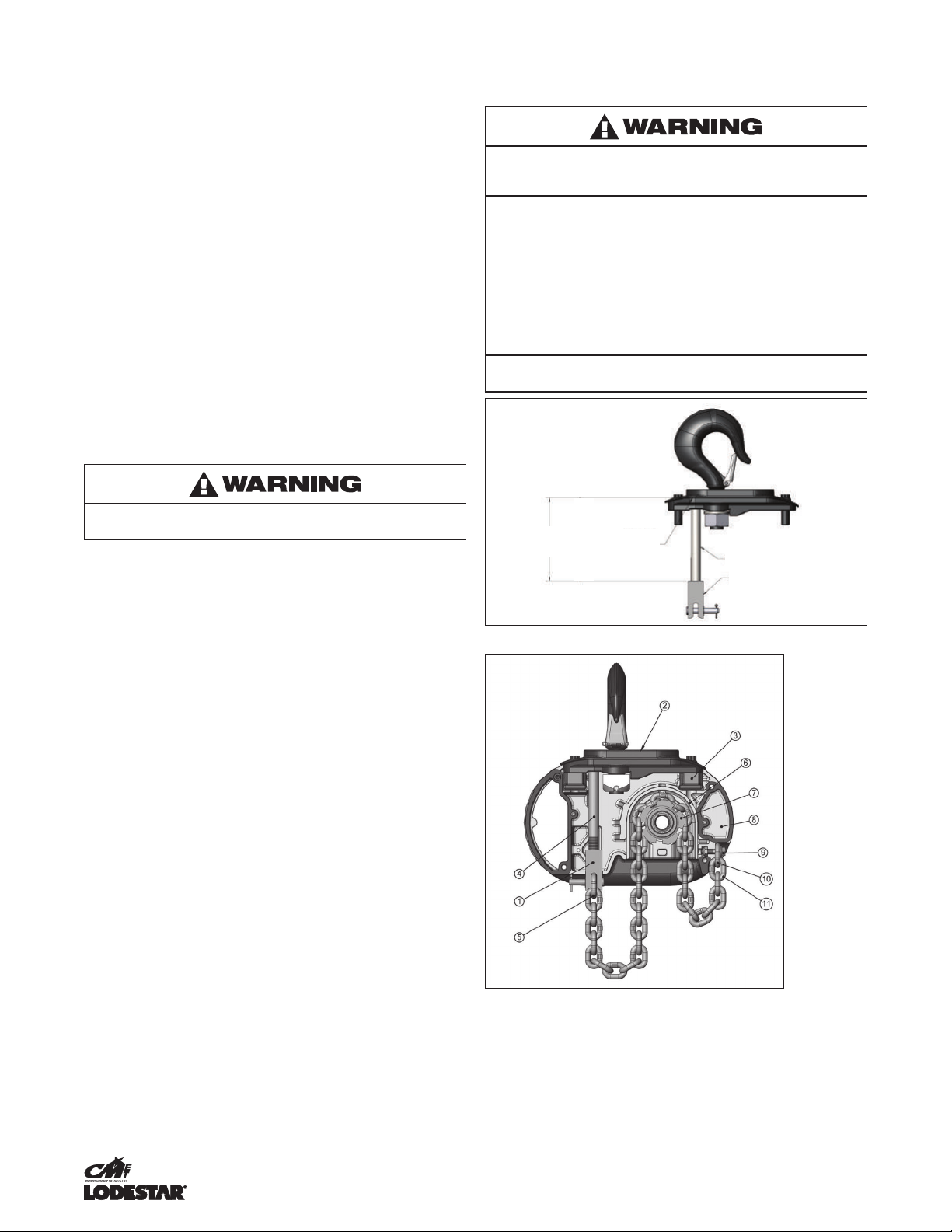
Operate hoist over the entire length of its rated lift, checking upper
and lower limit switches for correct operation as follows:
1. Press (UP) control and raise the lower hook until top of hook
block is about 12 inches (305 mm) below the hoist.
2. Cautiously continue raising the hook until the upper limit
switch stops the upward motion. The upper limit switch is
set at the factory to stop the hook block 8 links from the
bottom of all hoists.
3. If adjustment is necessary, see page 15.
4. Press(DOWN) control and cautiously lower hook until lower limit
switch stops the downward motion. On hoist operated in the
motor down orientation, maintain a minimum of 24" (610mm) of
chain freely hanging over the side of the hoist.
5. If adjustment is necessary, see page 15.
NOTE: If the hoist is equipped with a chain container/bag,
reset the upper and lower limit switches as indicated on
page 15.
Under no condition should the hook block or load be
permitted to come in contact with the chain container/bag.
If contact is made, the function of the chain container can
be interfered with and its fasteners imperiled.
NOTE: When chain bag is filled to capacity the bag must be
no more than 75% filled.
OPERATING INSTRUCTIONS
GENERAL
1. The Load-limiter is designed to slip on an excessive overload.
An overload is indicated when the hoist will not raise the load.
Also, some clutching noise may be heard if the hoist is loaded
beyond rated capacity. Should this occur, immediately release
the £(UP) control to stop the operation of the hoist. At this
point, the load should be reduced to the rated hoist capacity
or the hoist should be replaced with one of the proper capacity.
When the excessive load is removed, normal hoist operation is
automatically restored.
CAUTION: The Load-limiter is susceptible to overheating
and wear when slipped for extended periods. Under no
circumstance should the clutch be allowed to slip for more
than a few seconds.
Due to the above, a hoist equipped with a Load-limiter is not
recommended for use in any application where there is a possibility
of adding to an already suspended load to the point of overload.
This includes dumbwaiter installations, containers that are loaded
in mid-air, etc.
HOIST
1. Before picking up a load, check to see that the hoist is
directly overhead.
2. WHEN APPLYING A LOAD, IT SHOULD BE DIRECTLY UNDER
HOIST OR TROLLEY. AVOID OFF CENTER LOADING OF
ANY KIND.
3. Take up a slack load chain carefully and start load easily to
avoid shock and jerking of hoist load chain. If there is any
evidence of overloading, immediately lower the load and
remove the excess load.
4. DO NOT allow the load to swing or twist while hoisting.
5. DO NOT allow the load to bear against the hook latch.
SAFE OPERATING INSTRUCTIONS
AND PROCEDURES
For safety precautions and a list of Do’s and Do Not’s for safe
operation of hoists, refer to page 3.
1. Permit only competent personnel to operate unit.
2. When preparing to lift a load, be sure that the attachments
to the hook are rmly seated in hook saddle. Avoid off center
loading of any kind, especially loading on the point of hook.
3. Do not allow the load to bear against the hook latch. The latch
is to help maintain the hook in position while the chain is slack
before taking up slack chain.
4. Do not wrap the load chain around the load and hook onto itself
as a choker chain. Doing this will result in:
a. The loss of the swivel effect of the hook which could
result in twisted chain and a jammed lift wheel.
b. The upper limit switch, if so equipped, is bypassed
and the load could hit the hoist.
c. The chain could be damaged at the hook.
5. Before lifting load, check for twists in the load chain.
On double reeved units A twist can occur if the lower
hook block has been capsized between the strands
of chain. Reverse the capsize to remove twist.
6. On single reeved chain hoist used in conjunction with
head blocks and ground support systems, check for twists
between the hoist and head block. Twisted load can result
in a jammed liftwheel.
7. Do not use this or any other overhead materials handling
equipment for lifting persons.
8. Do not load hoist beyond the rated capacity shown on hoist
identication plate or on the hoist motor housing cover or hoist
back frame cover. Overload can cause immediate failure of
some load-carrying part or create a defect causing subsequent
failure at less than rated capacity. When in doubt, use the next
larger capacity CM Lodestar Hoist.
9. Warn personnel of your intention to lift a load in the area.
Tie off the load with auxiliary chains or cables before access
to the area beneath the load is permitted.
10. Do not operate hoist at unusual extremes of ambient
temperatures above 150º F (60º C) or below 0º F (-17º C).
STAGE OPERATION
Hoists can be removed from the road case by manual lifting,
or rigged while still in the case and power out.
Manual Lifting – It is recommended that two people be used to the
lift the hoist from the road case. The hoist can be lifted by grasping
the handles (if tted), the end covers, or the load chain. Never pull on
the electrical cable(s) even if equipped with an external strain relief.
When placed on the oor the hoist should be positioned on its side
with the chain pulled away to allow the chain to enter the hoist
without jamming if the hoist is to be operated.
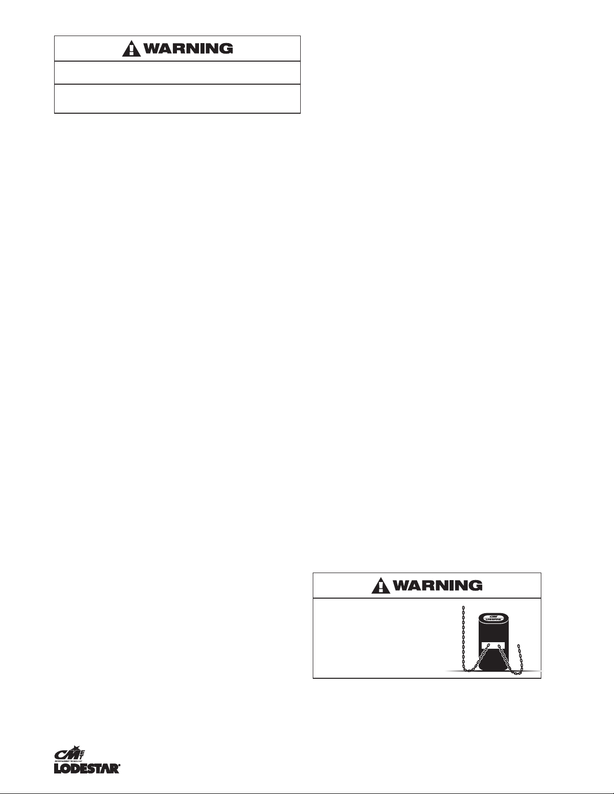
Never operate a Lodestar hoist
while standing on its end as in the
gure to the right.
The hoist may tip over and damage
the casing, but more importantly it
will cause the Lodestar to “drag”
against its brake putting extra strain
on the electric motor.
When running chain “in” the hoist should be laid on its side on the
ground / stage with the chain stretched out along the ground. The
“dead” end side of the hoist should be on the oor. With the hoist

11 P/N: 10001681 (REV AF) August 2020
in this position, gravity will hold the chain and allow it to run freely
through the hoist and help unravel any twists and prevent chain jam.
When running chain “out”, the same principal should be adopted but
this time with the “dead” end side of the hoist facing up. Again, this
will prevent twists causing chain jam.
When using Lodestar hoists with 2 chain falls (for example
on Model R or RR) you should check for twists in the chain.
The best way to check for this condition is to run the lower hook up
(without load) to within about 24 inches (600mm) of the hoist when
any twists will become apparent, if the chain has been properly
installed a twist can only occur if the lower block has been capsized
between the strands of chain – reverse capsize to remove twists.
• Before moving a truss use a verbal warning such as “truss
moving”. Always “bump” the hoists before lifting or lowering.
This will do 2 things:
– It will act as a warning to people around that the rig is about
to move should they not have heard your warning.
– Any problem with rigging or reeving will show up in this
“bumping through” – always leave enough chain to “bump”
without running out of chain.
• Always have one person in charge of moving the rig, but as
many “spotters” as necessary to watch any hoists the main
person cannot see.
• When replacing the hoist in the road case, the chain should
be run to the lower limit then operated in the up direction
for about 6 (152 mm) to 8 (203 mm) inches. This should be
done because:
– The ceiling height may be lower in this venue than the
next. If you run all the chain out, this assures enough chain
for the rigger to hit the point in the next venue regardless of
the height.
– Running off the lower limit prevents any damage to the
micro switch due to vibration as the hoist travels to the
next venue.
Allowing the load to bear against the hook latch and/or hook tip
can result in loss of load.
TO AVOID INJURY:
Do not allow the load and/or attachments to bear against the hook
latch and/or hook tip. Apply load to hook bowl or saddle only.
11. Take up a slack load chain carefully and start load easily to
avoid shock and jerking of hoist load chain. If there is any
evidence of overloading, immediately lower the load and
remove the excess load.
12. When lifting, raise the load only enough to clear the oor
or support and check to be sure that the attachments to
the hook and load are rmly seated. Continue lift only after
you are assured the load is free of all obstructions.
13. Do not allow the load to swing or twist while hoisting.
14. Never operate the hoist when ammable materials or vapors
are present. Electrical devices produce arcs or sparks that can
cause a re or explosion.
15. STAY ALERT! Watch what you are doing and use common
sense. Do not use the hoist when you are tired, distracted
or under the inuence of drugs, alcohol or medication causing
diminished control
INSPECTION
To maintain continuous and satisfactory operation, a regular
inspection procedure must be initiated to replace worn or damaged
parts before they become unsafe. Inspection intervals must be
determined by the individual application and are based on the type
of service to which the hoist will be subjected.
The type of service to which the hoist is subjected can be classied
as "Severe, "Normal", "Stand-by", "Rental", or "Out of Service".
Stand-by Service: Hoist operates 25 or fewer days a year,
but at least once.
Rental Service: Hoist is operated on an irregular schedule
determined by rental use.
Out of Service: Hoist does not operate for a period of a
year or longer.
Normal Service: Hoist operates 200 or fewer days a year,
but more than 25.
Severe Service: Hoist operates in excess of 200 days a year.
Two classes of inspection - frequent and periodic - must
be performed.
Frequent Inspections: These inspections are visual examinations
by the operator or other designated personnel. Records of such
inspections are not required. The frequent inspections are to be
performed monthly for normal service, weekly to monthly for heavy
service, and daily to weekly for severe service, and they should
include those items listed in Table 4.
Periodic Inspections: These inspections are visual inspections of
external conditions by an appointed person. Records of periodic
inspections are to be kept for continuing evaluation of the condition
of the hoist. Periodic inspections are to be performed yearly for
normal service, semi-annually for heavy service and quarterly for
severe service, and they are to include those items listed in Table 4.
CAUTION: Any deficiencies found during inspections are to be
corrected before the hoist is returned to service. Also, the ex-
ternal conditions may show the need for disassembly to permit
a more detailed inspection, which, in turn, may require the use
of nondestructive type testing.
PREVENTIVE MAINTENANCE
In addition to the above inspection procedure, a preventive
maintenance program should be established to prolong the useful
life of the hoist and maintain its reliability and continued safe use.
The program should include the periodic and frequent inspections
with particular attention being paid to the lubrication of the
various components using the recommended lubricants (see
online resources).
HOOK INSPECTION
Hooks damaged from chemicals, deformations or cracks, or any
visibly apparent bend or twist from the plane of the unbent hook,
excessive opening or seat wear must be replaced. Also, hooks
that are opened and allow the latch to not engage the tip must be
replaced. Any hook that is twisted or has excessive throat opening
indicates abuse or overloading of the unit. Inspect other load
sustaining parts, hook block screws, load pins and hook block
bodies for damage.
On latch type hooks, check to make sure that the latch is not
damaged or bent and that it operates properly with sufcient spring
pressure to keep the latch tightly against the tip of the hook and
allow the latch to spring back to the tip when released. If the latch
does not operate properly, it should be replaced. See Figure 12 to
determine when the hook must be replaced.
SUSPENSION BOLTS SHOULD BE REPLACED ANY TIME THE
SUSPENSION IS REMOVED FROM THE HOIST.

12 P/N: 10001681 (REV AF) August 2020
Table 4. INSPECTION TABLE
Service Classifications
Item
Severe Normal Stand By Rental Out of
Service
Frequent Inspections
Weekly to Monthly
Monthly
Every 3 Months
Prior to Next Use
or Rental
Prior to Reintroduction into Service
Hoist braking system for proper operation
Hooks and attachment hardware for correct assembly, damage, cracks,
twists, excessive throat openings, latch engagement, and latch operation
Load chain for adequate lubrication, signs of wear, damaged links, corrosion,
or foreign matter
Load chain for proper reeving and twists
Limit switches for function, if equipped
Periodic Inspections
Every 3 Months
Yearly
Yearly
Yearly
All items listed in Inspection Table for frequent inspections.
Evidence of loose screws, bolts or nuts.
Evidence of worn, corroded, cracked or distorted hook block body,
suspension screws, gears, bearings, chain dead end and chain pin.
Evidence of damage or excessive wear of the lift wheel and hook block
sheave chain pockets.
Link by link inspection of the chain for evidence of excessive interlink wear
and damage.
Evidence of chain guide wear or damage where the chain enters the hoist.
Evidence of excessive wear and/or damage of brake parts.
Proper brake adjustment.
If the hoist is equipped with a reversing contactor, inspect contactors for
functionality and free operation of the interlock.
Electrical cords, grommets, connectors, cables, and control station enclosure
(if applicable) for damage or wear.
Check bearings for excessive wear or damage.
Suspension components for damage, cracks, wear and correct operation.
Inspect all lower hook retaining nuts and pins for damage and secure fit.
Evidence of lubricant leakage.

13 P/N: 10001681 (REV AF) August 2020
HOOK REPLACEMENT CRITERIA
Based on ASME B30.10, hooks shall be removed from service
if damage such as the following is visible and shall only be returned
to service when approved by a qualied person:
1. Missing or illegible rated load identication or illegible
hook manufacturers' identication or secondary
manufacturer's identication.
2. Excessive pitting or corrosion. Cracks, nicks, or gouges.
3. Wear--any wear exceeding 10% of the original section
dimension of the hook or its load pin.
4. Deformation--any visibly apparent bend or twist from the plane
of the unbent hook.
5. Throat opening-any distortion causing an increase in the throat
opening of 5%, not to exceed 1/4" (6mm).
6. Inability to lock- any self-locking hook that does no lock.
7. Inoperative latch, any damaged latch or malfunctioning latch
that does not close the hook's throat.
8. Thread wear, damage, or corrosion.
9. Evidence of excessive heat exposure or unauthorized welding.
10. Evidence of unauthorized alterations such as drilling,
machining, grinding, or other modications.
HOOK REMOVE
CRITERIA
Based on 830-10 Hooks shall be removed from service
if damage such as the following is visible and shall only
be
returned to service when approved by a qualified
person:
!
a. Missing or illegible rated load identification or illegible
hook manufacturers' identification or
secondary
manufacturer's
identification.
!
b. Excessive pitting or corrosion.
c. Cracks, nicks, or gouges.
d.
Wear--any wear exceeding 10% of the original
section
dimension of the hook or its load pin.
!
e. Deformation--any visibly apparent bend or twist from
the
plane of the unbent
hook.
!
f. Throat opening-any distortion causing an increase in
the
throat opening of 5% not to exceed W' (6mm).
!
g. Inability to
lock-
any self-locking hook that
does
no
lock.
!
h. Inoperative latch any damaged latch or
malfunctioning
latch that does not close the hook's
throat.
!
i. Thread
wear,
damage, or
corrosion.
!
j. Evidence of excessive heat exposure
or
unauthorized welding.
!
k. Evidence of unauthorized alterations such as
drilling,
machining, grinding, or other
modifications.
Section A-A Section
B-B
!
!
!
Figure 14. Hook
Inspection
!
"#$%&'! ()*+,!-./%!0##1 ! ()*+,!0##1!
343!")5 ! 363!"78! 343!")5 ! 363!"78!
69:!;!< ! =>=?3! >?=3! =>@A3! >BC3!
DEF>GHHI! DGE>=HHI! DEB>BHHI! D=A>AHHI!
J9!(!;!(( ! =>E=3! =>FA3! =>@A3! >BC3!
DEE>EHHI! DGB>CHHI! DEB>BHHI! D=A>AHHI!
K9!KK!;!
KKL!
=>CF3! =>@E3! =>?G3! >?@3!
DEA>=HHI! DEM>GHH
I
! D@A>AHHI! DGE>?HHI!
!
!
!
!
!
!
Figure 12. Hook Inspection
Table 5. Hook Dimensions
Models Latch Type Hook Latchlok®Hook
"A" Max "B" Min "A" Max "B" Min
B, C & F 1.19"
(30.2mm)
.91"
(23.1mm)
1.48"
(37.7mm)
.75"
(18.8mm)
J, JJ, L, & LL 1.31"
(33.3mm)
1.08"
(27.5mm)
1.48"
(37.7mm)
.75"
(18.8mm)
R, RR & RRS 1.50"
(38.1mm)
1.43"
(36.2mm)
1.92"
(48.8mm)
.94"
(23.9mm)
INSPECTING THE LOAD CHAIN:
The chain must be inspected at regular intervals, with a minimum of
once annually. As the frequency of use increases, the time intervals
between inspections must be reduced. During inspection, the chain
link must be examined along their entire length, including the hidden
parts. If the lifting equipment is frequently used with a constant lifting
distance or in other words the switch from upward to downward
often takes place in the same area, a particularly thorough inspection
and lubrication is required in that area. Worn chain can also be an
indication of worn hoist components. For this reason, the hoist's
chain guides, hook blocks and liftwheel (sprocket) should be
examined for wear and replaced as necessary when replacing chain.
1. Check to see if chain is dirty or poorly lubricated.
2. Clean the chain with a non-caustic/non-acid type solvent and
make a link by link inspection for wear or cracks in the links,
twisted or deformed links. Chain with any one of these defects
must be replaced.
3. Slack the portion of the chain that normally passes over the
lift-wheel (sprocket) or idler sprocket on multi-reeved hoist.
Examine the chain links for wear (see Figure 13). If the wire
diameter anywhere on the link measures less than 90% of the
nominal wire diameter, the chain must be replaced.
UPSTANDING LINK
FLAT LAY
LINK
FLAT
LAY
MARKS
UPSTANDING
LINK MARKS
INTERLINK
MARKS
CHAIN
GUIDE
MARKS
NOSE
LOAD
MARKS
Figure 13. Chain Wear Areas
4. Based upon ASME B30.16, should also be checked for
elongation. Select an unworn, unstretched length of the chain
(at the slack end for example). Suspend the chain vertically
under tension and using a knife blade caliper type gauge,
measure the outside length of any convenient number of
links, 11 is recommended as shown in Figure 15. Measure the
same number of links in the used sections and calculate the
percentage in increased length. The chain should be replaced
if the length of the used portion is more than 1.5% longer
than the unused portion of the chain. Also, if the pitch of any
individual link has elongated by more than 5%, the chain
should be replaced.
Figure 14. Chain Dimensions
Table 6. Chain Dimensions
Models Pitch (P) Diameter (D)
B, C & F .745" (18.9mm) .250" (6.3mm)
J, JJ, L, LL, R, & RR .858" (21.8mm) .312" (7.9mm)
RRS 1.18" (30.0mm) .394 (10.0mm)
Figure 15. Gaging Load Chain Wear
Figure 16. Chain Embossing

14 P/N: 10001681 (REV AF) August 2020
IMPORTANT: Do not use replaced chain for other purposes such
as lifting or pulling. Load chain may break suddenly without visual
deformation. For this reason, cut replaced chain into short lengths
to prevent use after disposal.
REMOVAL AND INSTALLATION OF LOAD CHAIN
Improper installation (reeving) of the load chain can result
in a dropped load.
TO AVOID INJURY/DAMAGE:
• Verify use of proper size and type of hoist load chain
for specic hoist.
• Install load chain properly as indicated below.
USE ONLY CM EN (formerly DIN) OR STAR () GRADE LOAD
CHAIN AND CM REPLACEMENT PARTS. USE OF OTHER CHAIN
AND PARTS MAY BE DANGEROUS AND VOIDS FACTORY
WARRANTY.
Hoist load chain can be installed by any one of several methods.
The rst method is recommended when replacing severely worn
load chain and requires disassembling the hoist. Method 2 does
not require hoist disassembly and is the recommended method
for initial installation of load chain. Method 3 requires only partial
disassembly.
METHOD #1
a. Disconnect hoist from power supply.
b. Remove back frame cover and disengage the limit switch
guide plate from the traveling nuts, see page 16 or 17.
c. Detach loose end of load chain from hoist frame, see Figure
3. Also, on single reeved models, detach the lower hook block
from the load chain. On double reeved models R & RR unfasten
the dead end side of load chain.
d. Continue to disassemble the hoist and inspect the liftwheel,
chain guides, motor housing and gear housing which if worn
or damaged may cause premature failure of the new chain.
e. If the liftwheel pockets, in particular the ends, are worn or
scored, replace liftwheel. If chain guides and housing are worn,
cracked or damaged these parts should also be replaced.
f. Reassemble hoist with the new load chain inserted over the
liftwheel. Position chain with the weld on upstanding links away
from liftwheel and leave only one foot of chain hanging free on
loose end side. On double reeved models, make certain that
the new load chain is free of twists.
g. Attach the loose end link to chain and connect it to the hoist
frame with the loose end screw, washer and lockwasher, see
Figure 3. BE CERTAIN THERE IS NO TWIST.
h. For single reeved models, attach the hook block to load chain
and proceed to step K.
i. For double reeved models, run the hoist (UP) until only 914.4
mm (36” Inches) of chain remains on dead end side. This will
minimize the chance of introducing a twist between hook block
and hoist. Allow the chain to hang free to remove twists.
j. Using a wire as a starter, insert the chain, at link rst, into
lower hook block (upstanding links will have weld toward
sheave) and pull through. Insert last link into slot in dead end
block making certain that no twist exists in the reeving at any
point. Assemble dead end pin, washer and cotter pin as shown
in Figure 3.
k. Adjust limit switches as describe in Table 3, page 16. If the new
chain is longer than the old, check to be sure limit switch will
allow for new length of lift. In the event maximum adjustment
does not allow entire length of lift, check with CM® for
modication if necessary.
Do not allow hook block to hit hoist or allow load chain to
become taut between loose end screw and frame or else seri-
ous damage will result. If hook block should inadvertently hit
the hoist-the hoist frames, load chain and hook block should
be inspected for damage before further use.
METHOD #2
Treat the old load chain in hoist as a “starter chain” and proceed with
steps from Method #1, a, b, c and h thru k. If a starter chain is used,
the loose end link (two links required for double reeved models) can
serve as a temporary coupling link to connect together the starter
chain in the hoist and the new load chain to be installed. Then, under
power, reeve the new load chain through the liftwheel area, replacing
the starter chain in unit. Run enough chain through to attach loose
end link to hoist frame.
CAUTION: For double reeved models, be sure to disconnect
one of the loose end links from the load chain before attaching
it to the hoist.
METHOD #3
a. First proceed with Steps 1a, b & c from Method #1.
b. Then, carefully run the load chain out of the hoist.
c. Disconnect hoist from power supply.
d. Remove the electric brake assembly.
e. Rotate the brake hub by hand, at the same time feeding the
load chain into and through liftwheel area with hoist upside
down or using a wire to pull the load chain up onto the liftwheel
as explained in Method #1 step 1f.
f. Refer to Method #1 steps g thru j above to complete
the installation.

15 P/N: 10001681 (REV AF) August 2020
Using “Commercial” or other manufacturer’s parts to repair the
CM Lodestar Hoists may cause load loss.
TO AVOID INJURY:
Use only CM supplied replacement parts. Parts may look alike but
CM parts are made of specic materials or processed to achieve
specic properties
ORDERING INSTRUCTIONS
The following information must accompany all correspondence
orders for replacement parts:
1. Hoist Model Number from identication plate.
2. Serial number of the hoist stamped below identication plate.
3. Voltage, phase, hertz from the identication plate.
4. Length of lift.
5. Part number of part from parts list.
6. Number of parts required.
7. Part name from parts list.
NOTE: When ordering replacement parts, it is recommended
that consideration be given to the need for also ordering such
items as gaskets, fasteners, insulators, etc. These items may
be damaged or lost during disassembly or just unfit for future
use because of deterioration from age or service.
MAINTENANCE
LOAD-LIMITER
The Load-limiter should operate for the normal life of the hoist
without service. The device has been calibrated at the factory for
a specic model of hoist. For proper overload protection, be sure
before installing a Load-limiter that it is correct for the unit. This is
mechanical load protection only and contains no electrical sensing.
Models Load-limiter Part
Number
Load-limiter ID #
(marked on Protecor)
B C00000240 240
C, F C00000241 241
J, L, R C00000242 242
JJ, LL, RR, & RRS C00000243 243
For appropriate D8+ Load-Limiter see parts blow-out.
HOIST LUBRICATION
The lubricants used in and recommended for the Lodestar Hoist
may contain hazardous materials that mandate specic handling
and disposal procedures.
TO AVOID INJURY:
Handle and dispose of lubricants only as directed in applicable
material safety data sheets and in accordance with applicable local,
state and federal regulations.
GEARS
NOTE: To assure extra long life and top performance, be sure to
lubricate the various parts of the Lodestar Hoist using the lubri-
cants specified in lubrication section. If desired, these lubricants
may be purchased from CM. Refer to spare parts section for
information on ordering the lubricants.
The gearbox is packed at assembly with grease and should not
need to be renewed unless the gears have been removed from the
housing and degreased.
If the gears are removed from the housing, wipe the excess grease
off with a soft cloth and degrease the gears and housings. Upon
reassembly, add grease to gears and housing. Fully coat gear
teeth and pack gear box, Models B, C & F require 7 . oz. of
grease. Models J, JJ, L, LL, R, and RR require 15 . oz. of grease.
For Model RRS hoist: A total of 22 uid ounces of grease.
• The limit switch gears are of molded nylon and require
no lubrication.
• Apply a light lm of machine oil to the limit switch shaft threads
at least once a year.
BEARINGS
• All bearings and bushings, except the lower hook thrust bearing,
are pre-lubricated and require no lubrication. The lower hook thrust
bearing should be lubricated at least once a month.
CHAIN GUIDES, LIFTWHEEL
AND LOWER SHEAVE WHEEL
• When the hoist is disassembled for inspection and/or repair, the
chain guides, lower sheave wheel (on double chain units) and
liftwheel must be lubricated with Lubriplate Bar and Chain Oil 10-R
(Fiske Bros. Rening Co. or equivalent) prior to reassembly. The
lubricant must be applied in sufcient quantity to obtain natural
runoff and full coverage of these parts.
LOAD CHAIN
A small amount of lubricant will greatly increase the life of load chain.
Do not allow the chain to run dry.
Keep it clean and lubricate at regular intervals with Lubriplate Bar
and Chain Oil 10-4 (Fiske Bros. Rening Co.) or equal lubricant.
Normally, weekly lubrication and cleaning is satisfactory, but under
hot and dirty conditions, it may be necessary to clean the chain at
least once a day and lubricate it several times between cleanings.
When lubricating the chain, apply sufcient lubricant to obtain
natural run-off and full coverage, especially in the interlink area.
Used motor oils contain known carcinogenic materials.
TO AVOID INJURY:
Never use used motor oils as a chain lubricant. Only use Lubriplate
Bar and Chain Oil 10-R as a lubricant for the load chain.
DC BRAKE ASSEMBLY
The correct air gap between eld and armature is .008-.018 in
(0.2-0.45 mm) for models B, C, & F and .008-,020 in (0.2-0.5 mm)
for models J, JJ, L, LL, R, RR, & RRS. The DC brake is not
adjustable. As the friction material wears, the brake gap increases.
If the maximum air gap is reached, a new friction disc/rotor should
be installed.
LIMIT SWITCH ADJUSTMENT
If limit switch operation has been checked as described on page 9
and is not operating correctly or is not automatically stopping the
hook at a desired position, proceed as follows:
1. Disconnect hoist from power supply.
2. Remove back frame cover, see Figure 10.
3. The identication of upper and lower limit switches are
indicated on the ber insulator.

16 P/N: 10001681 (REV AF) August 2020
4. Loosen the 2 screws or spring back the rotatable guide to
disengage the travel nut.
Table 7. Limit Switch - Hook Travel
Model
Hook Travel w/
44 T.P.I. Shaft
(Standard)
Hook Travel w/
56 T.P.I. Shaft
(Standard)
Hook Travel w/
64 T.P.I. Shaft
(Standard)
Max Length of Lift Max Length of Lift Max Length of Lift
mftmftmft
C 63 206 80 262 91 299
B, F 5 15 41 133 46 152
J, L 39 127 49 162 56 185
JJ, LL 76 250 97 318 111 363
R 20 64 25 81 28 93
RR 38 124 48 158 55 181
RRS 38 125 48 159 55 182
Table 8. Limit Switch - Dimensions
Model
Hook Travel, per
Notch
A (minimum
distance between
top of hook block
and bottom of hoist)
B (minimum length
of loose end chain
non-inverted)
mm in mm in
C 52.8 2.08 38.1 1.50 6 links
B, F 26.9 1.06 38.1 1.50 6 links
J, L 30.5 1.20 38.1 1.50 8 links
JJ, LL 116.8 4.60 63.5 2.50 8 links
R 15.2 0.60 63.5 2.50 8 links
RR 29.7 1.17 63.5 2.50 8 links
RRS 30.0 1.18 63.5 2.50 30 links
Figure 17. Limit Switches, Models B-F
1. Limit switch sub-assy
2. Limit switch shaft
3. Traveling nuts
4. Guide plate
5. Screws
Figure 18. Rotatable Limit Switches, Models B-F
SETTING UPPER LIMIT SWITCH
After completing steps 1 thru 4
5. Refer to Table 8 -The "A" Dimensions given are the minimum
distance that should be set between the top hook block and
the bottom of the hoist.
CAUTION: THE “A” DIMENSIONS SHOWN IN TABLE 8
ARE THE MINIMUM ALLOWED FOR SAFE OPERATION
AND SHOULD NOT BE REDUCED.
6. Reconnect hoist to power supply.
7. Run hook to the desired upper position, cautiously operating
the hoist without a load.
8. Disconnect hoist from power supply.
9. Moving one travel nut toward the other increases hook travel
and away from the other decreases the travel. Now, turn the nut
nearest the switch indicated as the “UPPER LIMIT SWITCH”
until it just breaks the limit switch contacts, cautious not to
allow the movement of the other travel nut if previously set.
An audible click will be heard as the switch opens. Continue
to rotate the nut toward the switch an additional one full tooth.
Figure 19. Limit Switches, Models J-RRS
1. Limit switch sub-assy
2. Limit switch shaft
3. Traveling nuts
4. Guide plate
5. Screws

17 P/N: 10001681 (REV AF) August 2020
Figure 20. Rotatable Limit Switches, Models J-RRS
10. Securely reposition the guide plate in the slot
11. Reconnect hoist to power supply and check the stopping point
of hook by rst lowering the hook about 2 feet (61 cm), then
raise the hook by jogging cautiously until the upper limit switch
stops upward motion. The stopping point of hook should be the
desired upper position. If not, repeat the above instructions.
12. Double check setting by lowering the hook about 2 feet (61 cm)
and then run the hook into the upper limit with (UP) control
held depressed.
13. Fine adjustment of the upper limit setting may be obtained
by inverting the stationary guide plate in Step 10. The offset
on the plate gives adjustments equivalent to 1/2 notch, see
Table 8 for the “Hook Travel Per Notch of Limit Switch Nut.”
When inverting the plate, it may be necessary to use the notch
adjacent to the one used in the preliminary setting.
SETTING LOWER LIMIT SWITCH
After completing steps 1 thru 4
5. Refer to Table 8 -The “B”dimensions given are the minimum
length of loose end chain left on the loose side of the lift
wheel when the hook is positioned at the lowest allowable
hook position.
CAUTION: THE “B” DIMENSIONS SHOWN IN TABLE 8
ARE THE MINIMUM ALLOWED FOR SAFE OPERATIONS
AND SHOULD NOT BE REDUCED.
6. Reconnect hoist to power supply.
7. Run hook to the desired lower position, cautiously operating the
hoist without a load.
8. Disconnect hoist from power supply.
9. Moving one travel nut toward the other increases hook travel
and away from the other decreases hook travel. Now, turn
the nut nearest the switch indicated as the “LOWER LIMIT
SWITCH” until it just breaks the limit switch contacts, cautious
not to allow the movement of the other travel nut if previously
set. An audible click will be heard as the switch opens.
Continue to rotate the nut toward the switch an additional
one full tooth.
10. Securely reposition the guide plate in the slot.
11. Reconnect hoist to power supply and check the stopping point
of hook by rst raising the hook about 2 feet (61cm ) then lower
the hook by jogging cautiously until the lower limit switch stops
downward motion. The stopping point of the hook should be
the desired lower position, if not repeat the above instructions.
12. Double check setting by raising the hook about 2 feet (61 cm)
and then run the hook into the lower limit with (DOWN) control
held depressed.
13. Fine adjustment of the lower limit setting may be obtained by
inverting the stationary guide plate in Step 10. (Not available
with the rotatable guide plate). The offset on the gives
adjustments equivalent to 1/2 notch, see Table 8 for the “Hook
Travel Per Notch of Limit Switch Nut”. When inverting the plate,
it may be necessary to use the notch adjacent to the one used
in the preliminary setting.
CONVERTING LIMIT SWITCH GUIDES
1. Disconnect the hoist from the power supply system.
2. Refer to the exploded views and remove the back frame cover
from the hoist.
3. Remove and discard the limit switch guide plate - retaining
the 2 screws.
4. Refer to Figure 17 and 19 and assemble the limit switch guide
plate to the limit switch bracket. Secure using the
2 screws.
TESTING OF MECHANICAL
OVERLOAD PROTECTION
Before using, all altered, repaired or used hoists that have
not been operated for the previous 12 months shall be tested
by the user for proper operation. First test the unit without
a load and then with a light load of 22.7 kg. (50 lb.) times the
number of load supporting parts of load chain to be sure that
the hoist operates properly and that the brake holds the load
when the control is released. Next test with a load of *125%
of rated capacity. In addition, hoists in which load sustaining
parts have been replaced should be tested with *125% of
rated capacity by or under the direction of an appointed
person and written report prepared for record purposes.
After this test, check that the Load-limiter functions.
*If Load-limiter prevents lifting of a load of 125% of rated
capacity, reduce load to rated capacity and continue test.
NOTE: For additional information on inspection and testing,
refer to Code B30.16 “Overhead Hoists” obtainable from
ASME Order Department, 22 Law Drive, Box 2300,
Fairfield, NJ 07007-2300, U.S.A

18 P/N: 10001681 (REV AF) August 2020
TABLE 9. TROUBLESHOOTING CHART
SYMPTOM PROBABLE CAUSE CORRECTIVE ACTION
1.) Hook does not respond to the
control station or control device
A.) No voltage at hoist-main line or branch
circuit switch open; branch line fuse
blown or circuit breaker tripped.
A.) Close switch, replace fuse or reset breaker.
B.) Phase failure (single phasing, three
phase unit only)-open circuit, grounded
or faulty connection in one line of supply
system, hoist wiring, reversing contactor,
motor leads or windings.
B.) Check for electrical continuity and repair or
replace defective part.
C.) Upper or lower limit switch has opened
the control circuit.
C.) Press the “other” control and the hook should
respond. Adjust limit switches as described
on page 15.
D.) 1. Open control circuit-open
2. Shorted winding in transformer
3. Reversing contactor coil
4. Loose connection
5. Broken wire in circuit
6. Mechanical binding in contactor
7. Control station contacts not closing
or opening.
D.) Check electrical continuity and repair or replace
defective part.
E.) Wrong voltage or frequency. E.) Use the voltage and frequency indicated on
hoist identication plate. For three phase dual
voltage unit, make sure the connections at the
voltage change board or PCB are the proper
voltage as described on page 8.
F.) Low Voltage. F.) Correct low voltage condition as described
on page 9.
G.) Brake not releasing-open or shorted coil
winding; armature binding.
G.) Check electrical continuity and connections.
Check that correct coil has been installed. The
coil for three phase dual voltage unit operates
at 230 volts when the hoist is connected for
either 230 volt or 460 volt operation. Check
brake adjustment as described on page 15.
H.) Excessive load. Mechanical load
protector slipping.
H.) Reduce loading to the capacity limit of hoist
as indicated on the identication plate.
2.) Hook moves in wrong direction. A.) Phase reversal (three phase unit only). A.) Refer to installation instruction on page 8.
3.) Hook lowers but will not raise. A.) Excessive load. Mechanical load
protector slipping.
A.) See item 1H.
B.) Open hoisting circuit-open or shorted
winding in reversing contactor coil loose
connection or broken wire in circuit;
control station contacts not making;
upper limit switch contacts open.
B.) Check electrical continuity and repair or replace
defective part. Check operation of limit switch
as described on page 9.
C.) Phase failure (three phase unit only). C.) See item 1B.
4.) Hook raises but will not lower A.) Open lowering circuit-open or shorted
winding in reversing contactor coil, loose
connection or broken wire in circuit;
control station contacts not making;
lower limit switch contacts open.
A.) Check electrical continuity and repair or replace
defective part. Check operation of limit switch
as described on page 9.
5.) Hook lowers when hoisting control
is operated.
A.) Phase failure (three phase unit only). A.) See item 1B.
B.) Phase reversal (three phase unit only). B.) Refer to installation instruction on page 8.

19 P/N: 10001681 (REV AF) August 2020
TABLE 9. TROUBLESHOOTING CHART
SYMPTOM PROBABLE CAUSE CORRECTIVE ACTION
6.) Hook does not stop promptly. A.) Brake slipping. A.) Check brake adjustment as described
on page 15.
B.) Excessive load. B.) See item 1H.
7.) Hoist operates sluggishly. A.) Excessive load. A.) See item 1H.
B.) Low voltage. B.) Correct low voltage condition as described
on page 9.
C.) Phase failure or unbalanced current in
the phases (three phase unit only).
C.) See item 1B.
D.) Brake dragging. D.) Check brake air gap as described
on page 15.
8.) Motor overheats. A.) Low voltage. A.) Correct low voltage condition as described
on page 9.
B.) Excessive load. B.) See item 1H.
C.) Extreme external heating. C.) Above an ambient temperature of 40°C.
(104°F.), the frequency of hoist operation
must be limited to avoid overheating of motor.
Special provisions should be made to ventilate
the space or shield the hoist from radiation.
D.) Frequent starting or reversing. D.) Avoid excessive inching, jogging or plugging.
This type of operation drastically shortens the
motor and contactor life and causes excessive
brake wear.
E.) Phase failure or unbalanced current
in the phase (three phase unit only).
E.) See item 1B.
F.) Brake dragging. F.) Check brake air gap as described
on page 15.
9.) Hook fails to stop at either or both
ends of travel.
A.) Limit switches not opening circuits. A.) Check switch connections, electrical continuity
and mechanical operation. Check the switch
adjustment as described on page 15.
B.) Limit Switch Shaft not rotating. B.) Check for damaged Limit Switch gears.
C.) Traveling nuts not moving along shaft;
guide plate loose; shaft or nut threads
damaged.
C.) Tighten guide plate screws. Replace
damaged part.
10.) Hook stopping point varies. A.) Limit switch not holding adjustment. A.) See item 9.
B.) Brake not holding. B.) Check the brake air gap as described
on page 15.
C.) Binding of Limit Switch Shaft. C.) Check Limit Switch Bearing for proper seating.

20 P/N: 10001681 (REV AF) August 2020
ELECTRICAL DATA
TO DETECT OPEN AND SHORT CIRCUITS IN
ELECTRICAL COMPONENTS
Open circuits in the coils of electrical components may be detected
by isolating the coil and checking for continuity with an ohmmeter
or with the unit in series with a light or bell circuit.
Shorted turns are indicated by a current draw substantially above
normal (connect ammeter in series with suspected element and
impose normal voltage) or D.C. resistance substantially below
normal. The current method is recommend for coils with very
low D.C. resistance.
Motor current draw in the stator should be measured with the rotor
in place and running. Brake, relay and contactor coil current should
be measured with the core iron in operating position.
Table 10a. Transformer Data
Transformer Voltage Leads *D.C. Resistance
(Ohms)
115 to 24 X2 to X1
H2 to H1
1.1
14.4
115 to 48 X2 to X1
H2 to H1
3.5
14.4
230/460 to 24
220/380 to 24
220/415 to 24
X2 to X1
H2 to H1
H4 to H3
1.1
106
130
230/460 to 48
220/380 to 48
220/415 to 48
X2 to X1
H2 to H1
H4 to H3
3.5
106
130
230/460 to 115
220/380 to 115
220/415 to 115
X2 to X1
H2 to H1
H4 to H3
21
106
130
575 to 24 X2 to X1
H2 to H1
1.1
373
575 to 48 X2 to X1
H2 to H1
3.5
373
575 to 115 X2 to X1
H2 to H1
21
373
Lodestar Equipped with PCB
230/460 to 24
220/380 to 24
220/415 to 24
Pin 1 to 5
Pin 5 to 7
Pin 9 to 13
245
635
3.2
230/460 to 115
220/380 to 115
220/415 to 115
Pin 1 to 5
Pin 5 to 7
Pin 9 to 13
205
658
51
Table 10b. Contactor Data
Models Contactor Coil
Voltage
Nominal Current
(Amps)
*D.C. Resistance
(Ohms)
B thru RRS
115 0.04 29.75
48 0.09 56.3
24 0.19 14.9
*Resistance Values listed are nominal and they may vary slightly from component to
component.
**On dual voltage units (230/460-3-60, 220/380-3-50 and 220/415-3-50), brake coils operate
on 230 (220) volts.
Table 10c. Electric Brake Data
Models DC Brake Coil
Voltage
Nominal Current
(Amps)
*D.C. Resistance
(Ohms)
B, C and F
103 0.243 424.4
205 0.122 1681
255 0.098 2601
J, L and R 103 0.311 331.5
J, JJ, L, LL, R, RR,
& RRS
205 0.161 1273
255 0.118 2167
Table 10d. Motor Data
Models/
Cap.
Volts-
Phase-
Hertz
H.P.
(kW)
Full Load
Current
(Amps)
Motor
Leads
*D.C.
Resistance
(Ohms)
B -1/4 Ton
(250 kg)
C -1/4 Ton
(250 kg)
F - 1/2 Ton
(500 kg)
115/230-1-60
1/2
(.37)
7.2/3.6
1 to 2
1.9
3 to 4
5 to 8 3.6
110/220-1-50 6.4/3.2
1 to 2
2.7
3 to 4
5 to 8 3.5
230/460-3-60 1.8/.9
1 to 4
7.82 to 5
220/380-3-50 2.1/1.0
3 to 6
8 to 9
15.6
220/415-3-50 2.1/1.0
8 to 7
9 to 7
J - 1/2 Ton
(500 kg)
L - 1 Ton
(1000 kg)
R - 2 Ton
(2000 kg)
115/1-60
1
(.74)
9.8 1 to 2
1.1
9.8 3 to 4
110/1-50
11.6 3 to 4 1.1
11.6 5 to 8 1.3
J - 1/2 Ton
(500 kg)
L - 1 Ton
(1000 kg)
R - 2 Ton
(2000 kg)
230/460-3-60
1
(.74)
3.0/1.5
1 to 4
4.72 to 5
220/380-3-50 3.6/1.8
3 to 6
8 to 9
9.4
220/415-3-50 3.6/1.8
8 to 7
9 to 7
JJ - 1/2
Ton
(500kg)
LL - 1 Ton
(1000kg)
RR - 2 Ton
(2000kg)
RRS - 2
Ton
(2000kg)
230/460-3-60
2
(1.5)
5.8/2.9
1 to 4
2.22 to 5
220/380-3-50 6.4/3.3
3 to 6
8 to 9
9.4
220/380-3-50 6.4/3.3
8 to 7
9 to 7
This manual suits for next models
3
Table of contents
Other CM Chain Hoist manuals

CM
CM 5623A User manual

CM
CM Hurricane Mini 360 User manual

CM
CM Bandit BAN07505 User manual

CM
CM 653 Series User manual

CM
CM Lodestar XL User manual

CM
CM Lodestar D8 PLUS Installation and operating instructions

CM
CM 635 Series User manual

CM
CM Hurricane 360 Operating manual

CM
CM 646 Series User manual

CM
CM 622A Series User manual
Popular Chain Hoist manuals by other brands

R&M
R&M LOADMATE LM Series Installation and maintenance manual

Robur
Robur 8143 Operation manual and instructions

POWERTEX
POWERTEX PLH-S1 Instructions for use

Ingersoll-Rand
Ingersoll-Rand QUANTUM QMT Series Parts, operation and maintenance manual

KITO
KITO Chain Sling 100 owner's manual

goldwinch
goldwinch GTD 300 Assembly & Operating Instruction