CM Shopstar User manual

P/N 192047138 Rev AA November 2017
Before installing hoist, fill in the information below.
Model Number
Serial No.
Purchase Date
Follow all instructions and warnings for inspecting,
maintaining and operating this hoist.
The use of any hoist presents some risk of personal injury
or property damage. That risk is greatly increased if proper
instructions and warnings are not followed. Before using
this hoist, each operator should become thoroughly familiar
with all warnings, instructions and recommendations in this
manual. Retain this manual for future reference and use.
Forward this manual to the hoist operator. Failure to operate
equipment as directed in manual may cause injury.
Columbus McKinnon Corporation
205 Crosspoint Parkway
Getzville, NY 14068
ELECTRIC CHAIN HOIST
OPERATING, MAINTENANCE
& PARTS MANUAL
SHOPSTAR
SLC SERIES
SHOPHOIST
SLM SERIES

2
P/N 192047138 Rev AA November 2017
CM HOIST PARTS AND SERVICES ARE AVAILABLE IN THE UNITED STATES AND IN CANADA
As a CM Hoist and Trolley user you are assured of reliable repair and parts services through a network of Master Parts Depots and Service
Centers that are strategically located in the United States and Canada. These facilities have been selected on the basis of their demonstrated
ability to handle all parts and repair requirements promptly and efciently. To quickly obtain the name of the Master Parts Depot or Service
Center located nearest you, call (800) 888-0985. Fax: (716) 689-5644.
LAS PIEZAS Y REPARACIONES DE LOS POLIPASTOS DE CM
ESTÁN ASEGURADAS EN ESTADOS UNIDOS Y CANADÁ
Como usuario de un polipasto y carro de CM le aseguramos cualquier reparación o la disponibilidad de cualquier pieza de repuesto a
través de una red de almacenes de piezas de repuesto y centros de servicio situados estratégicamente en Estados Unidos y Canadá. Estas
instalaciones se han seleccionado en base a su capacidad demostrada en la reparación de equipos y suminstro de piezas de repuesto de
forma rápida y ecaz. Para obtener la dirección del almacén de piezas de repuesto o del centro de servicio más cercano, llame al teléfono
(800) 888-0985. Fax: (716) 689-5644 (sólo en Estados Unidos y Canadá).
LE SERVICE DE RÉPARATION ET DE PIÈCES POUR PALANS CM
EST DISPONIBLE AUX ÉTATS-UNIS ET AU CANADA
Soyez assurés qu'en temps d'utilisateur de palan et treuil CM, d'un service de réparation et de pièces able par l'entremise d'un réseau de
Centres de service et de Dépôts de pièces maîtresses qui sont stratégiquement situés aux États-Unis et au Canada. Ces établissements ont
été sélectionnés sur une base de leur habileté démontrée à s'occuper promptement et efcacement des besoins de réparation de pièces.
Appelez le (800) 888-0985, Fax: (716) 689-5644 pour obtenir rapidement le nom du dépôt de pièces maîtresses ou du centre de service situé
le plus près.

3
P/N 192047138 Rev AA November 2017
Improper operation of a hoist can create a potentially
hazardous situation which, if not avoided, could result in
death or serious injury. To avoid such a potentially hazardous
situation, THE OPERATOR SHALL:
a. NOT operate a damaged, malfunctioning or unusually
performing hoist.
b. NOT operate the hoist until you have thoroughly read and
understood this Operating, Maintenance and Parts Manual.
c. NOT operate a hoist which has been modied.
d. NOT lift more than rated load for the hoist.
e. NOT use hoist with twisted, kinked, damaged, or worn load
chain.
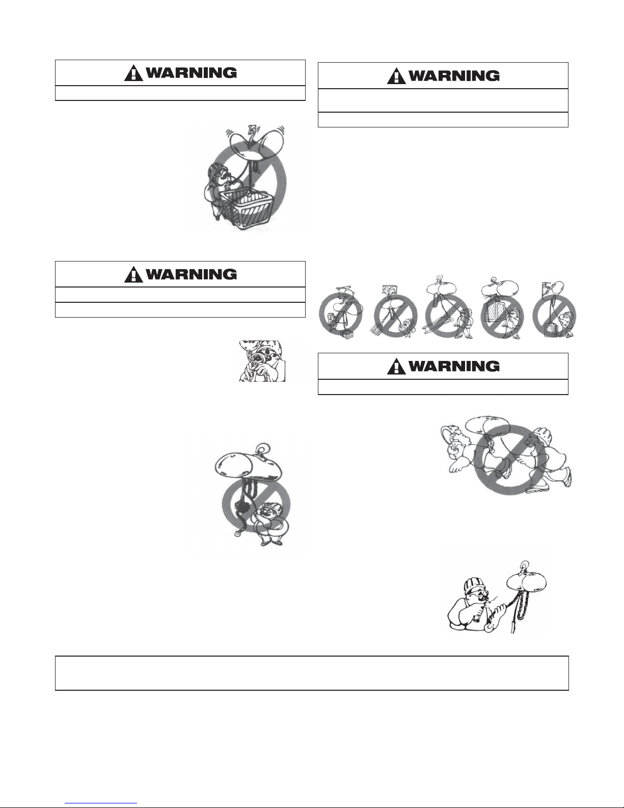
f. NOT use the hoist to lift, support, or transport people.
g. NOT lift loads over people.
h. NOT operate a hoist unless all persons are and remain clear
of the supported load.
i. NOT operate unless load is centered under hoist.
j. NOT attempt to lengthen the load chain or repair damaged
load chain.
k. Protect the hoist’s load chain from weld splatter or other
damaging contaminants.
l. NOT operate hoist when it is restricted from forming a
straight line from hook to hook in the direction of loading.
m. NOT use load chain as a sling, or wrap chain around load.
n. NOT apply the load to the tip of the hook or to the hook
latch.
o. NOT apply the load unless load chain is properly seated in
the chain wheel(s) or sprocket(s).
p. NOT apply load if bearing prevents equal loading on all load
supporting chains.
q. NOT operate beyond the limits of the load chain travel.
r. NOT leave load supported by the hoist unattended unless
specic precautions have been taken.
s. NOT allow the load chain or hook to be used as an electrical
or welding ground.
t. NOT allow the load chain or hook to be touched by a live
welding electrode.
u. NOT remove or obscure the warnings on the hoist.
v. NOT operate a hoist on which the safety placards or decals
are missing or illegible.
w. NOT operate a hoist unless it has been securely attached to
a suitable support.
x. NOT operate a hoist unless load slings or other approved
single attachments are properly sized and seated in the
hook saddle.
y. Take up slack carefully - make sure load is balanced and
load holding action is secure before continuing.
z. Shut down a hoist that malfunctions or performs unusually
and report such malfunction.
aa. Make sure hoist limit switches function properly.
ab. Warn personnel of an approaching load.
Improper operation of a hoist can create a potentially
hazardous situation which, if not avoided, could result
in minor or moderate injury. To avoid such a potentially
hazardous situation, THE OPERATOR SHALL:
a. Maintain rm footing or be otherwise secured
when operating the hoist.
b. Check brake function by tensioning the hoist prior
to each lift operation.
c. Use hook latches. Latches are to retain slings, chains, etc.
under slack conditions only.
d. Make sure the hook latches are closed and not supporting
any parts of the load.
e. Make sure the load is free to move and will clear
all obstructions.
f. Avoid swinging the load or hook.
g. Make sure hook travel is in the same direction as shown
on the controls.
h. Inspect the hoist regularly, replace damaged or worn parts,
and keep appropriate records of maintenance.
i. Use factory parts when repairing the unit.
j. Lubricate load chain per hoist manufacturer’s
recommendations.
k. NOT use the hoist’s overload limiting clutch to measure
load.
l. NOT use limit switches as routine operating stops.
They are emergency devices only.
m. NOT allow your attention to be diverted from operating
the hoist.
n. NOT allow the hoist to be subjected to sharp contact with
other hoists, structures, or objects through misuse.
o. NOT adjust or repair the hoist unless qualied to perform
such adjustments or repairs.
SAFETY PRECAUTIONS
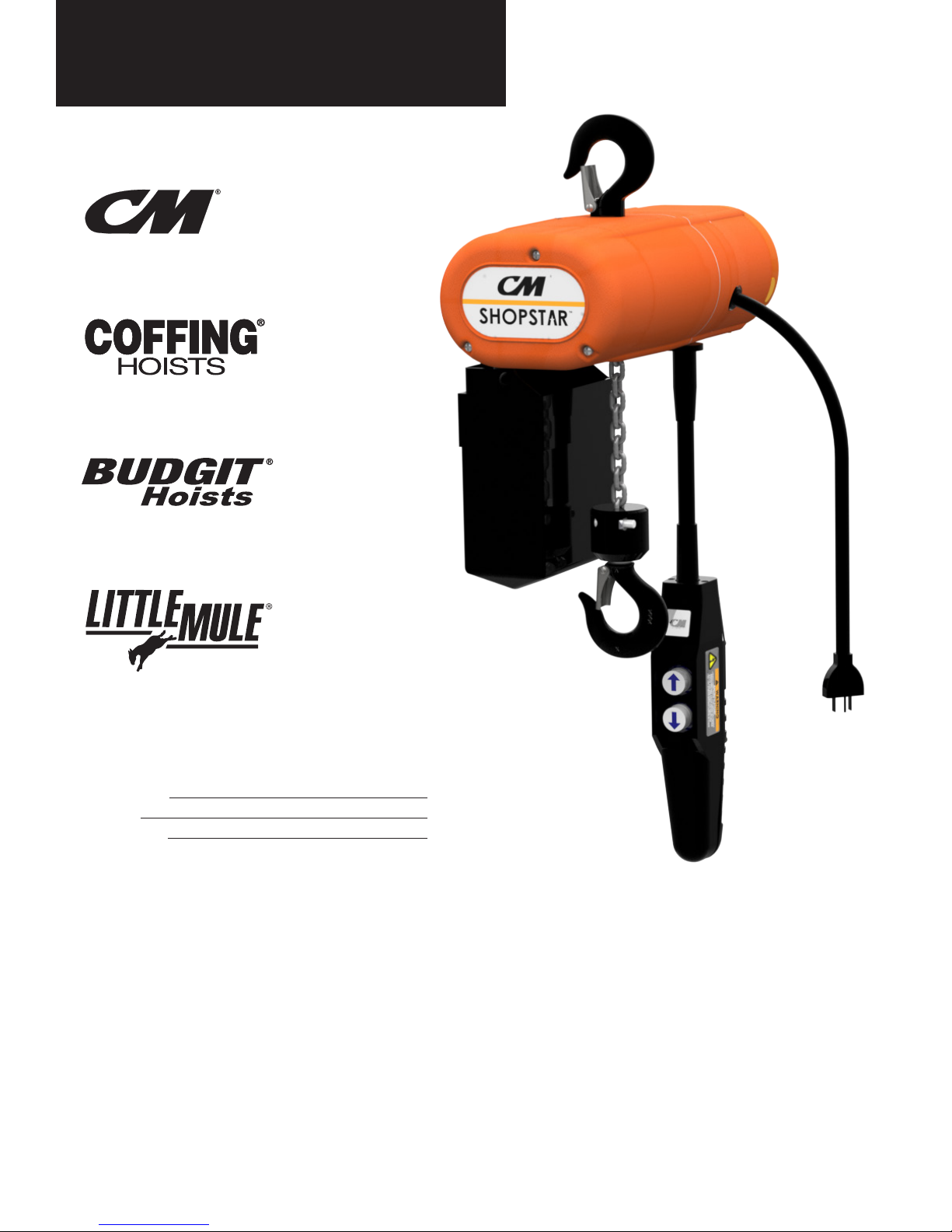
Each Shopstar Electric Hoist is built in accordance with the
specications contained herein and at the time of manufacture
complied with our interpretation of applicable sections of the National
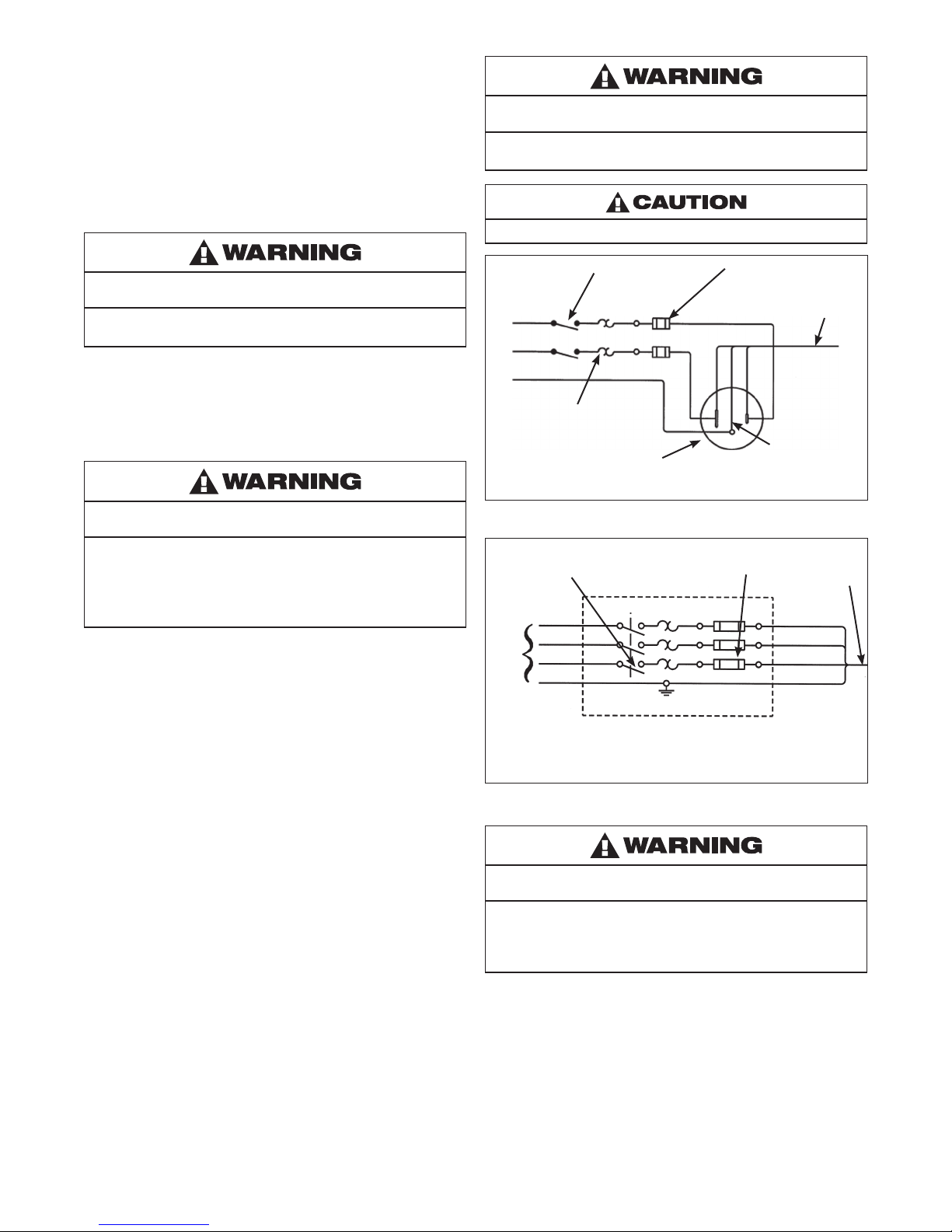
Electrical Code (ANSI/NFPA 70). Installers are required to provide
current overload protection and grounding in keeping with the code.
Check each installation for compliance with the applicable sections of
the code as well as the National, State and Local Codes that may apply
to the installation. In addition, safety code requirements associated
with the operation of a hoist in the inverted (theatrical) position (chain
port up), as with any mechanical equipment, vary depending upon
locality. Therefore, before installing the hoist, the user should consult
his insurance company and/or local authority to see if a deviation is
required to permit the use of the hoist in this particular application.
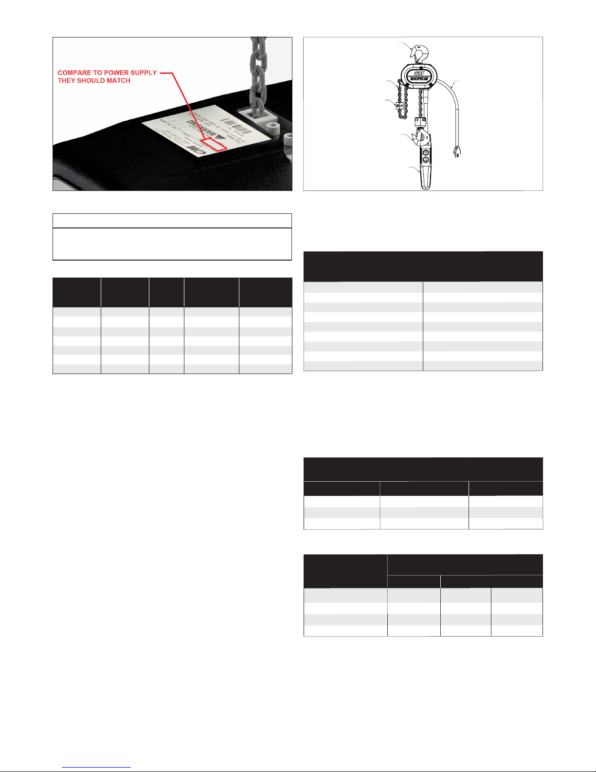
The safety laws for elevators, lifting of people and for dumbwaiters
specify construction details that are not incorporated into
the hoists. For such applications, refer to the requirements of
applicable state and local codes, and the American National Safety
Code for elevators, dumbwaiters, escalators and moving walks
(ASME A17.1). We cannot be responsible for applications other
than those for which the equipment is intended.
*Copies of this standard can be obtained from ASME Order Department,
22 Law Drive, PO Box 2300, Faireld, NJ 07007- 2300, U.S.A.,
www.asme.org, 800-843-2763.
THIS SYMBOL POINTS OUT IMPORTANT SAFETY
INSTRUCTIONS WHICH IF NOT FOLLOWED COULD
ENDANGER THE PERSONAL SAFETY AND/OR PROPERTY
OF YOURSELF AND OTHERS. READ AND FOLLOW ALL
INSTRUCTIONS IN THIS MANUAL AND ANY PROVIDED
WITH THE EQUIPMENT BEFORE ATTEMPTING TO
OPERATE YOUR SHOPSTAR HOIST.

4
P/N 192047138 Rev AA November 2017
DO NOT PULL AT AN ANGLE. BE SURE HOIST AND LOAD ARE
IN A STRAIGHT LINE.
DO NOT USE LOAD CHAIN AS A SLING.
USE HOIST PROPERLY
Be sure hoist is solidly held in the uppermost part of the support
hook arc.
Be sure hoist and load are in a straight line.
Do not pull at an angle.
Be sure load is hooked securely. Do not tip load the hook. Do not
load hook latch. Hook latch is to prevent detachment of load under
slack chain conditions only.
Do not use load chain as a sling. Such usage damages the chain
and lower hook.
Do not operate with hoist head resting against any object. Lift the
load gently. Do not jerk it.
DO NOT LIFT PEOPLE OR LOADS OVER PEOPLE
LIFT PROPERLY
Do not lift co-workers with a
hoist.
Make sure everyone is clear of
the load when you lift.
Do not remove or obscure
operational warning notices.
MAINTAIN PROPERLY
CLEANING
Hoists should be kept clean and free of dust, dirt, moisture, etc.,
which will in any way affect the operation or safety of the equipment.
LUBRICATION
Chain should be properly lubricated.
AFTER REPAIRS
Carefully operate the hoist
before returning it to full service.
HOIST SAFETY IS UP TO YOU...
DO NOT LIFT MORE THAN RATED LOAD.
CHOOSE THE RIGHT HOIST FOR THE JOB...
Choose a hoist with the capacity for
the job. Know the capacities of your
hoists and the weight of your loads.
Then match them.
The application, the size and type
of load, the attachments to be used
and the period of use must also be
taken into consideration in selecting
the right hoist for the job.
Remember, the hoist was
designed to ease our burden and
carelessness not only endangers the
operator, but in many cases, a valuable load.
DO NOT OPERATE DAMAGED OR MALFUNCTIONING HOIST.
DO NOT OPERATE WITH TWISTED, KINKED, OR DAMAGED CHAIN.
INSPECT
All hoists should be visually inspected
before use, in addition to regular, periodic
maintenance inspections.
Inspect hoists for operations warning notices
and legibility.
Deciencies should be noted and brought to the attention of
supervisors. Be sure defective hoists are tagged and taken out
of service until repairs are made.
Under no circumstances should you operate a malfunctioning hoist.
Check for gouged, twisted,
distorted links and foreign material.
Do not operate hoists with twisted,
kinked, or damaged chain links.
Load chain should be properly
lubricated.
Hooks that are bent, worn, or whose
openings are enlarged beyond
normal throat opening should not
be used. If latch does not engage
throat opening of hook, hoist should
be taken out of service.
Chains should be checked for
deposits of foreign material which
may be carried into the hoist
mechanism.
Check brake for evidence of slippage under load.
VIOLATIONS OF ANY OF THE WARNINGS LISTED MAY RESULT IN SERIOUS PERSONAL INJURY TO THE OPERATOR
OR NEARBY PERSONNEL BY NATURE OF RELEASED LOAD OR BROKEN HOIST COMPONENTS.

5
P/N 192047138 Rev AA November 2017
FOREWORD
This manual contains important information to help you properly install, operate and maintain your hoist for maximum performance, economy
and safety.
Please study its contents thoroughly before putting your hoist into operation. By practicing correct operating procedures and by carrying out
the recommended preventive maintenance suggestions, you will experience long, dependable and safe service. After you have completely
familiarized yourself with the contents of this manual, we recommend that you carefully le it for future reference.
The information herein is directed to the proper use, care and maintenance of the hoist and does not comprise a handbook on the broad
subject of rigging.
Rigging can be dened as the process of lifting and moving heavy loads using hoists and other mechanical equipment. Skill acquired through
specialized experience and study is essential to safe rigging operations. For rigging information, we recommend consulting a standard
textbook on the subject.
TABLE OF CONTENTS
Master Parts Depots And Service Centers ........................................ 2
Safety Precautions ............................................................................. 3
Foreword ........................................................................................... 5
SPECIFICATIONS
Electric Chain Hoists .......................................................................... 6
Repair/Replacement Policy................................................................ 6
Accessories........................................................................................ 7
INSTALLATION
Unpacking .......................................................................................... 8
Mounting the Hoist............................................................................. 8
Power Supply System........................................................................ 8
Three Phase Hoists ............................................................................ 9
Checking for Adequate Voltage at Hoist ............................................ 9
OPERATION
General............................................................................................. 10
MAINTENANCE
Inspection......................................................................................... 11
Preventive Maintenance................................................................... 11
Inspection Table ............................................................................... 12
Hook Inspection ............................................................................... 13
Hook Replacement Criteria .............................................................. 13
Inspecting The Load Chain .............................................................. 13
Lubrication........................................................................................ 14
Electric Brake ................................................................................... 15
TROUBLESHOOTING
General............................................................................................. 16
ELECTRICAL DATA
Open or Short Circuit in Electrical Components .............................. 17
WIRING
General............................................................................................. 19
DISASSEMBLY-ASSEMBLY
General............................................................................................. 23
Load Chain Removal/Installation...................................................... 23
Cutting Chain ................................................................................... 24
Testing .............................................................................................. 24
Repair Parts List............................................................................... 25
ORDERING INSTRUCTIONS
General............................................................................................. 25
RECOMMENDED SPARE PARTS
General............................................................................................. 25
LIST OF TABLES
TABLE DESCRIPTION PAGE
1 Specications .................................................................... 6
2 Nominal Voltage................................................................. 9
3 Start-up Voltage................................................................. 9
4a-b Adequate Power Supply.................................................... 9
5 Electrical Data for Components....................................... 18
6 Torque Settings................................................................ 23
LIST OF ILLUSTRATIONS
FIG. DESCRIPTION PAGE
1 Chain Container................................................................. 7
2 Latchlok Hook.................................................................... 7
3 632 Trolley.......................................................................... 7
4 UT Trolley........................................................................... 7
5 CM Rocket Universal Pendant Control.............................. 7
6 Single Phase Systems ....................................................... 8
7 Three Phase Systems........................................................ 8
8 Nameplate ......................................................................... 9
9 Hoist Components............................................................. 9
10 Hook Inspection............................................................... 13
11 Chain Inspection.............................................................. 14
12 Chain Wear Areas ............................................................ 14
13 Chain Identication.......................................................... 14
14 Brake Field Assembly ...................................................... 15
15 Drive Shaft Assembly....................................................... 15
16 Brake Assembly............................................................... 15
17 110-1-50, 115-1-60 Hoists
without Contactor (Orange Control Station).................... 19
18 110-1-50, 115-1-60 Hoists
with Contactor (Black Control Station) ............................ 19
19 220-1-50, 230-1-60 Hoists
with Contactor (Black Control Station) ............................ 20
20 220-3-50, 230-3-60 Hoists
with Contactor (Black Control Station) ............................ 20
21 380-3-50, 415-3-50, 460-3-60 Hoists
with Contactor (Black Control Station) ............................ 21
22 230-3-60, 400-3-50 PCB
(Printed Circuit Board) Unit.............................................. 21
23 575-3-60 Hoists with Contactor
(Black Control Station)..................................................... 22
24 Main Frame...................................................................... 23
25 Stator Installation............................................................. 23
26 Chaining Hoist ................................................................. 23
27 Chaining Diagram ............................................................ 24
28 Chain Stop....................................................................... 24
29 Cutting Chain by Nicking................................................. 24
30 Cutting Chain with a Bold Cutter..................................... 24

6
P/N 192047138 Rev AA November 2017
SPECIFICATIONS
Standard features of the Electric Chain Hoist include:
• Alloy steel, oblique lay liftwheel that provides constant chain
speed and reduces chain wear.
• Hoistaloy® load chain for long and dependable service.
• Grease lubricated, hardened spur gears provide smooth and
quiet operation.
• Thermally protected, hoist duty motor.
• Forged steel upper and lower hooks with latch.
• ProtectorTM that prevents lifting dangerous overloads.
• D.C. disc type motor brake plus regenerative braking.
• 10 foot (3 M) lift. Longer lifts can be supplied on a per order basis.
• 6 foot (1.8 M) power cord with three prong plug for grounding on
115-1-50/60 units. 6 foot (1.8 M) power cord with provisions for
grounding is standard on 220-1-50 and three phase units.
• Rugged NEMA 4 (weatherproof) control station is suspended
on a TYPE SO cord six feet (2.8 M) below the bottom of the
hoist. Longer cords can be provided on a per order basis.
• Lightweight die cast aluminum frames and covers.
• Ball or needle bearings at all rotating points.
• Compact, yet rugged, design provides minimum headroom
and long, trouble-free service
• 220-1-50, 380 to 460-3-50/60, 220 to 240-3-50/60 and 575-3-60
units available. Lift speeds are based on 60 hertz power supply.
For 50 hertz power supply lift speeds will be 5/6 of those indicated.
• Speeds and capacities based on Table 1, below.
• UL and cUL listed.
• Lifetime Warranty.
Follow all instructions and warnings for inspecting, maintaining
and operating this hoist.
The use of any hoist presents some risk of personal injury or
property damage. That risk is greatly increased if proper instructions
and warnings are not followed. Before using this hoist, each operator
should become thoroughly familiar with all warnings, instructions,
and recommendations in this manual.
Retain this manual for future reference and use.
Forward this manual to the hoist operator. Failure to operate the
equipment as directed in the manual may cause injury. Before
putting hoist into service, ll in the information below. Refer to the
hoist identication plate.
Model Number
Serial No.
Purchase Date
Voltage
Rated Load
Table 1 - Specifications
Lift 6
fpm 8 fpm 12
fpm
13.3
fpm
16
fpm
20
fpm
24
fpm
40
fpm
250 lb x x x
300 lb x x x x
500 lb x x x x x
550 lb x
600 lb x x
1000 lb x x x
REPAIR/REPLACEMENT POLICY
All Electric Chain Hoists are inspected and performance
tested prior to shipment. If any properly maintained hoist
develops a performance problem, due to a material or
workmanship defect, as veried by the factory, repair or
replacement of the unit will be made to the original purchaser
without charge. This repair/replacement policy applies only to
Shopstar Hoists installed, maintained and operated as outlined
in this manual, and specically excludes hoists subject to normal
wear, abuse, improper installation, improper or inadequate
maintenance, hostile environmental effects and unauthorized
repairs/modications.
We reserve the right to change materials or design if, in our opinion,
such changes will improve our product. Abuse, repair by an
unauthorized person, or use of non-factory replacement parts
voids the guarantee and could lead to dangerous operation.
All Shopstar Electric Chain Hoists are backed with a lifetime
warranty. Refer to the back cover for details and limitations.
Alterations or modication of hoist and use of non-factory repair
parts can lead to dangerous operation and injury.
TO AVOID INJURY:
• Do not alter or modify equipment.
• Do use only factory replacement parts.

7
P/N 192047138 Rev AA November 2017
Figure 1 - Chain Container
Figure 2 - Latchlok Hook
Figure 3 - 632 Trolley
Figure 4 - UT Trolley
Figure 5 - CM® Rocket™ Universal Pendant Control
ACCESSORIES
HOOK SUSPENSIONS
Swivel and rigid type hook suspensions are available for all Shopstar
Electric Hoists. However, swivel type hook suspensions are normally
recommended for most applications.
CHAIN CONTAINER
This accessory item (Figure 1) is used to hold the slack chain
and it is supplied with mounting hardware and instructions.
Chain containers are recommended for those applications where
slack chain will interfere with the load or drag on the oor as may
more often be the case with the double-reeved units (500, 600,
1,000lb - 226, 272, and 453kg). Chain containers are shipped
separately and can be furnished for units already in service.
LATCHLOK®HOOKS
CM’s Latchlok hooks are available (Figure 2) to replace the standard
upper and lower hooks used on the Shopstar Electric Hoists.
CM SERIES 632 TROLLEY
This lightweight, yet, rugged, manual push type trolley (Figure 3)
is designed to t a wide range of monorail beams and negotiate
tight curves. Provides mobility of your hoist.
CM UNIVERSAL (UT) TROLLEY
The CM Universal Trolley (UT) is designed to t virtually all
Columbus McKinnon powered chain hoists up to 3 ton capacities.
The rugged UT is available as a convertible plain unit, a geared unit
ideal for precise hoist positioning, and a motorized unit that’s perfect
for applications requiring high cycling and long distance hoist travel.
CM® ROCKET™ UNIVERSAL PENDANT CONTROL
The CM Rocket Pendant Control is engineered for maximum
operator comfort, while delivering the precision control your
application demands.

8
P/N 192047138 Rev AA November 2017
INSTALLATION
UNPACKING
After opening the carton, carefully inspect the hoist frame, cords,
hooks, chain and control station for damage that may have occurred
during shipment. If there is damage, refer to the packing slip
envelope.
Make sure that the power supply to which the hoist is to be
connected is the same as that shown on the identication plate
located on bottom of hoist.
Operating a unit with obvious external damage may cause load to
drop and that may result in personal injury and/or property damage.
TO AVOID INJURY:
Carefully check unit for external damage prior to installation.
MOUNTING THE HOIST
Hang the hoist from its intended support. The structure used to
support the hoist must have sufcient strength to withstand several
times the load imposed. If in doubt consult a registered engineer
and local building codes.
Suspending the hoist from an inadequate support may allow the
hoist and load to fall and cause injury and/or property damage.
TO AVOID INJURY:
Make sure the attachment point has sufcient strength to hold
several times the hoist and its rated load. Using the upper hook,
hang the hoist from the support. Be sure hoist is solidly held
in the uppermost part of the hook arc and the latch is tightly
against the hook tip.
POWER SUPPLY SYSTEM
(Refer to Figure 6 or 7). To insure proper operation, to avoid damage
to hoist and electrical system and to reduce the risk of electric shock
or re, the branch circuit supplying power to the hoist must:
1. Have ample capacity to prevent excessive voltage drop during
starting and operation (refer to Figure 8). When determining
the size of branch circuit components and conductors,
special consideration should be given to the starting
current-amps (approximately three times that shown on the
hoist identication plate) and the length of the conductors.
As a minimum, the system should be rated for 15 amps and
it should have #16 AWG, or larger, wiring.
2. Be in accordance with the National Electrical Code (ANSI/
NFPA-70) and applicable National, State and Local Codes.
3. Effectively ground the hoist in accordance with National
Electrical Code and other applicable codes. Proper grounding
provides a path of least resistance for electric current to reduce
the risk of electric shock. The power cord of the hoist includes
a green-yellow wire for grounding the hoist to the external
power supply system. Be sure that the receptacle opening that
receives the longest prong is properly grounded. If grounding
is to be through the trolley trackwheels, each section of the
runway must be grounded to the building ground system
using metal to metal connections.
4. Include slow blow type fuses or inverse trip time circuit
breakers to permit the hoist to start and accelerate load.
5. Include a disconnecting means capable of being locked in the
“open” position.
Failure to properly ground the hoist presents the danger of
electric shock.
TO AVOID INJURY:
Permanently ground the hoist as instructed in this manual.
To reduce the risk of electric shock or injury, use indoors only.
Figure 6 - Single Phase Systems
Black
Blue Brown
Green-Yellow
White
Ground
Manual
Disconnect
Switch
Slow Blow Fuses or
Inverse Time Circuit
Breakers
Hoist Power
Cord
Thermal
Overload
Relay
Receptacle Rated for 15 amp Minimum (220-1-50 units do
not include Power Cord Plug). Wire Blue and Brown Wires to
Fuses or Circuit Breakers and Green-Yellow Wire to Ground.
Figure 7 - Three Phase Systems
Black
Grey
Brown
Green-Yellow
Slow Blow Fuses or
Inverse Time Circuit
Breakers Hoist Power
Cord
Incoming Power
Must be per National Electrical Code and These Devices are
to be Supplied by the User.
L1
L2
L3
Ground
Manual
Disconnect
Switch
Failure to provide a proper power supply system for the hoist may
cause hoist damage and offers the potential for a re.
TO AVOID INJURY:
Provide the hoist with a 15 amp, minimum, overcurrent protected
power supply per the National Electrical Code (ANSI/NFPA 70) and
applicable local codes as instructed in this manual.

9
P/N 192047138 Rev AA November 2017
Figure 8 - Nameplate
Note
In this manual, nominal voltages are used when referring to power
supply systems. However, with no modication, the Shopstar
Hoist will operate on a range of voltages as indicated below:
Table 2 - Nominal Voltage
NOMINAL
VOLTAGE
VOLTAGE
RANGE HERTZ TRADITIONAL
CONTACTOR
PRINTED
CIRCUIT BOARD
230 208-240 60 AVAILABLE AVAILABLE
460 440-480 60 AVAILABLE NOT AVAILABLE
220 200-240 50 AVAILABLE AVAILABLE
380 365-395 50 AVAILABLE AVAILABLE
415 400-415 50 AVAILABLE AVAILABLE
430 415-430 50 AVAILABLE NOT AVAILABLE
575 550-600 60 AVAILABLE NOT AVAILABLE
THREE PHASE HOISTS
Since the motor in a three phase hoist can rotate in either direction,
depending on the manner in which it is connected to the power
supply, the direction of hook movement must be checked during
the original installation and each time hoist is moved to a new
location as follows:
1. Move the manual disconnect switch handle to the
“OFF” position.
2. Connect the BROWN, GREY AND BLACK wires of hoist
power cord to load side of disconnect switch. Connect
the GREEN-YELLOW wire of hoist power cord to power
supply ground.
3. Move the manual disconnect switch handle to the
“ON” position.
4. Depress the (up) control. If the hook moves in the up direction,
the hoist is ready for operation. If the hook lowers, move
the disconnect switch handle to the “OFF” position and
interchange the BLACK and BROWN leads at the disconnect
switch. Move the disconnect switch handle to the “ON”
position and the hoist is now ready for operation.
CHECKING FOR ADEQUATE VOLTAGE AT HOIST
The hoist must be supplied with adequate electrical power for proper
operation and to reduce problems that may result from insufcient
power (low voltage). These include:
• Noisy hoist operation due to brake and/or contactor chatter.
• Heating of the hoist motor and other internal components as well
as heating of wires and connectors in the circuit feeding the hoist.
• Failure of the hoist to lift the load due to motor stalling.
• Blowing fuses or tripping circuit breakers.
• Dimming of lights or slowing of motors connected to the
same circuit.
UPPER HOOK
LOOSE END OF CHAIN
CHAIN STOP
LOWER HOOK
POWER
CORD
CONTROL STATION
Figure 9 - Hoist Components
For proper operation and to avoid these low voltage problems,
voltage (measured at end of the power cord while lifting rated load)
should be as the following chart indicates.
Table 3 - Start-up Voltage
NOMINAL MINIMUM * MIN. VOLTAGE
POWER OPERATING AT INSTANT
SUPPLY VOLTAGE OF START
115-1-50/60 108
220-1-50 198
208-3-60 187
220-3-50 198
230-3-60 207
380-3-50 365
415-3-50 399
460-3-60 414
575-3-60 518
*The drop in voltage upon energizing the hoist should not be below the value listed.
Low voltage can also be caused by using an undersize extension
cord to supply power to the hoist. The following charts should be
used to determine the size wires in the extension cord in order to
minimize the voltage drop between the power source and the hoist.
115-1-50/60 units with contactor, 220-1-50 units and three phase
units (hoists with black control station)
Table 4a - Adequate Power Supply
MAXIMUM LENGTH OF EXTENSION CORD
Wire Size Single Phase Hoist Three Phase Hoist
#16 A.W.G. 135 ft (40m) 245 ft (73m)
#14 A.W.G. 220 ft (66m) 395 ft (120m)
#12 A.W.G. 354 ft (107m) 630 ft (192m)
115-1-50/60 units without contactor (hoists with orange control station)
Table 4b - Adequate Power Supply
LENGTH OF CONTROL
CORD ft(m)
MAXIMUM LENGTH OF EXTENSION CORD
BASED ON SIZE OF WIRE
#16 AWG #14 AWG #12 AWG
1.0 to 10.0 (0.3 to 3.0) 105ft (32m) 170ft (51m) 270ft (82m)
11.1 to 20.0 (3.1 to 6.0) 75ft (22m) 120ft (36m) 190ft (58m)
21.1 to 30.0 (6.1 to 9.0) 45ft (14m) 70ft (21m) 110ft (33m)
31.1 to 40.0 (9.1 to 12.0) 15ft (4.5m) 20ft (6m) 35ft (11m)
After the hoist is suspended from its support and you have made
sure the power supply complies with the above, the hoist is ready
for operation.
On the Double units, cut and discard the ties used to hold the two
strands of chain together. With no load on the lower hook, depress
the UP button in the control station and raise the lower hook
until it is about 2 feet below the bottom of the hoist. Check both
strands of chains for twists. Twists occur if the lower hook block
has been capsized between the strands of chain during packing,
shipment and/or handling. Reverse the capsize to remove twists.

10
P/N 192047138 Rev AA November 2017
OPERATING INSTRUCTIONS
The hoist is equipped with a Protector™ that is designed to
allow the rst gear to slip on an excessive overload. An overload
is indicated when the hoist speed slows down, it raises the load in
a jerky manner or it will not lift the load at all. Also, some clutching
noise may be heard if the hoist is loaded beyond rated capacity.
Should this occur, immediately release the UP button to stop the
operation of the hoist. At this point, the load should be reduced to
the rated capacity or the hoist should be replaced with one of the
proper capacity. When the excessive load is removed, normal hoist
operation is automatically restored.
The Protector™ is susceptible to overheating and wear when slipped
for extended periods. Under no circumstance should the Protector
be allowed to slip for more than a few seconds.
Due to the above, the hoist is not recommended for use in any
application where there is a possibility of adding to an already
suspended load to the point of overload. This includes dumbwaiter
installations, containers that are loaded in mid-air, etc. Also, if the
hoist is used at unusual extremes of ambient temperatures, above
150º F (65ºC). or below 15ºF (-9ºC)., changes in lubricant properties
may permit the hoist to raise larger loads than under normal
operating conditions and present possibility of damage or injury.
On units without contactor (hoists with orange control station)
it is necessary to stop the hoist before changing direction.
Therefore, when lowering a load, the push button in the control
station must be released momentarily before the UP button is
depressed to raise the load. If this is not done, the hoist will
continue to operate in the down direction while the UP push
button is depressed, and it will continue to lower the load until
the control push button is released. As a result, the direction
must not be reversed quickly (plug reversed).
There are no electrical switches to stop the operation of the hoist
at the upper and lower limits of lift. As a result, it is necessary to
release the push button in the control station to stop the hoist
components from damage. However, continued, prolonged or
repeated slipping of the Protector will damage the Protector and
cause overheating of the internal hoist components.
Allowing the hook block to run into the hoist when raising a load or
allowing the chain stop to run into the hoist when lowering a load
may break the chain and allow the load to drop.
TO AVOID INJURY:
Do not allow the hook block or the chain stop to contact the hoist frame.
Hoist operation is controlled by depressing the control station push
buttons. Depressing the UP push button will move the load hook
toward the hoist head; depressing the DOWN push button will move
the load hook away from the hoist head.
The UP and DOWN buttons are momentary type and the hoist will
operate in the selected direction as long as the button is held in the
depressed position. Release the push button and the hoist will stop.
It is preferred that the load always be tied off with auxiliary chains or
cables before access to the area beneath the load is permitted. As
an alternative, the system may be designed such that malfunction or
failure of one hoist’s load bearing components does not cause load
loss and/or overloading of any other hoists in the system. Note that
in such a system, hoist performance and function must be monitored
visually or with the use of load cells. Check the supporting structure
to which the load hook is to be attached. Make sure the attachment
point as well as the structure have sufcient strength to withstand
several times the load imposed. If in doubt, consult a registered
engineer and local building codes.

11
P/N 192047138 Rev AA November 2017
Attaching the load hook to an inadequate support may allow the
hoist and load to fall and cause injury and/or property damage.
TO AVOID INJURY:
Make sure the structure and the load hook attachment point have
sufcient strength to hold several times the hoist and rated load.
1. When preparing to lift a load, be sure that the attachments to
the load hook are rmly seated in hook saddle. Avoid off center
loading of any kind, especially loading on the point of the hook.
2. When lifting, raise the load only enough to clear the oor or
support and check to be sure that the attachments to the
hook and load are rmly seated. Continue lift only after you are
assured the load is free of all obstructions.
3. Do not load the hoist beyond the rated capacity shown on the
brake end cover. Overloading can cause immediate failure of
some load-carrying part or create a defect causing subsequent
failure at less than rated capacity. When in doubt, use the next
larger capacity of hoist.
4. Do not use this or any other overhead materials
handling equipment for lifting persons or allow people
on unsecured load.
5. Stand clear of all loads and avoid moving a load over heads
of other personnel. Warn personnel of your intention to move
a load in their area. Do not leave unsecured load over people.
6. Do not leave the load suspended in the air unattended.
7. Permit only qualied personnel to operate unit.
8. Do not wrap the load chain around the supporting structure and
hook onto itself as a choker chain. Doing this will result in:
1. The loss of the swivel effect of the load hook which could
mean twisted chain and a jammed liftwheel.
2. The chain could be damaged at the load hook.
9. On the Double-reeved hoists, check for twists in the load chain.
A twist can occur if the lower block has been capsized between
the strands of chain. Reverse the capsize to remove twist.
10. Do not allow a load to bear against the hook latch. The latch
is to help maintain the hook in position while the chain is slack
before taking up the slack chain.
11. Take up a slack load chain carefully and start load easily to
avoid shock and jerking of hoist chain. If there is any evidence
of overloading, immediately lower the load and remove the
excess load.
12. Do not allow the load to swing or twist while hoisting.
13. Never operate the hoist when ammable materials or vapors
are present. Electrical devices produce arcs or sparks that can
cause a re or explosion.
14. STAY ALERT! Watch what you are doing and use common
sense. Do not use the hoist when you are tired, distracted or
under the inuence of drugs, alcohol or medication causing
diminished control.
TO AVOID INJURY:
DO NOT Lift more than rated load.
DO NOT Operate with twisted, kinked or damaged chain.
DO NOT Operate damaged or malfunctioning hoist
DO NOT Lift people, loads over people, allow people on
unsecured load or leave unsecured load over people.
DO NOT Operate hoist when load hook is not centered overhoist.
DO NOT Permit load hook block to contact hoist frame or
chain container.
DO Replace damaged or malfunctioning hook latch.
DO Keep load chain well oiled.
DO Read ASME B30.16 Safety Code for Hoist and appropriate
operating instructions.
MAINTENANCE
INSPECTION
To maintain continuous and satisfactory operation, a regular
inspection procedure must be initiated to replace worn or damaged
parts before they become unsafe. Inspection intervals must be
determined by the individual application and are based on the type
of service to which the hoist will be subjected. The type of service to
which the hoist is subjected can be classied as “Severe”, “Normal”,
or “Stand by Service” per ANSI E1.6-2.
Severe Service: Hoist operates in excess of 200 days a year.
Normal Service: Hoist operates 200 or fewer days a year but
more than 25.
Stand by Service: Hoist operates 25 or fewer days per year
but at least once per year.
Two classes of inspection - frequent and periodic – must
be performed.
Frequent Inspections: Visual examination shall be performed by
a competent person following the items listed in the inspection table
Records of such inspections are recommended.
Periodic Inspections: Inspection shall be performed by a qualied
person following the items listed in inspection table. Records of
this inspection shall be recorded and retained for a minimum of 36
months after the hoist is taken out of service.
Lifting and lowering functions shall be tested under no-load
conditions. (Testing through complete rated lift length is
not required). Brake(s) operation shall be tested under
no-load conditions.
Any deciencies found during inspections are to be corrected
before the hoist is returned to service. Also, the external
conditions may show the need for disassembly to permit a
more detailed inspection, which, in turn, may require the use of
nondestructive type testing.
PREVENTIVE MAINTENANCE
In addition to the above inspection procedure, a preventive
maintenance program should be established to prolong the useful
life of the hoist and maintain its reliability and continued safe use.
The program should include the periodic and frequent inspections
with particular attention being paid to the lubrication of the various
components using the recommended lubricants (see page 15).
Note
To perform some of the periodic inspections, it is necessary to
partially disassemble the hoist. Refer to Disassembly - Assembly
starting on page 23.
Any deciencies noted must be corrected before the hoist is
returned to service. Also, the external conditions may show the
need for more detailed inspection which, in turn, may require the
use of nondestructive-type testing.
Any parts that are deemed unserviceable are to be replaced with
new parts before the unit is returned to service. It is very important
that the unserviceable parts be destroyed to prevent possible future
use as a repair item and properly disposed of.
Allowing a load to bear against the hook latch and/or hook tip can
result in loss of load.
TO AVOID INJURY:
Do not allow a load to bear against the hook latch and/or hook tip.
Apply load to hook bowl or saddle only

12
P/N 192047138 Rev AA November 2017
Frequent Inspections
Inspection Table
Service Classifications
ITEM
Severe Normal Stand By Rental Out of
Service
Weekly to Monthly
Monthly
Every 3 Months
Prior to Next Use
or Rental
Prior to Reintroduction into Service
Hoist braking system for proper operation.
Hooks and attachment hardware for correct assembly,
damage, cracks, twists, excessive throat openings, latch
engagement, and latch operation.
Load chain for adequate lubrication, signs of wear, damaged
links, corrosion, or foreign matter.
Load chain for proper reeving and twists.
Limit switches for function, if equipped
Periodic Inspections
Every 3 Months
Yearly
Yearly
Yearly
All items listed in Inspection Table for frequent inspections.
Evidence of loose screws, bolts or nuts.
Evidence of worn, corroded, cracked or distorted hook block
body, suspension screws, gears, bearings, chain dead end
and chain pin.
Evidence of damage or excessive wear of the lift wheel and
hook block sheave chain pockets.
Link by link inspection of the chain for evidence of excessive
interlink wear and damage.
Evidence of chain guide wear or damage where the chain
enters the hoist.
Evidence of excessive wear and/or damage of brake parts.
Proper brake adjustment.
If the hoist is equipped with a reversing contactor, inspect
contactors for functionality and free operation of the interlock.
Electrical cords, grommets, connectors, cables, and control
station enclosure (if applicable) for damage or wear.
Check bearings for excessive wear or damage.
Suspension components for damage, cracks, wear and
correct operation.
Evidence of lubricant leakage.

13
P/N 192047138 Rev AA November 2017
HOOK INSPECTION
Hooks damaged from chemicals, deformations or cracks, or any
visibly apparent bend or twist from the plane of the unbent hook,
excessive opening or seat wear must be replaced. Also, hooks
that are opened and allow the latch to not engage the tip must be
replaced. Any hook that is twisted or has excessive throat opening
indicates abuse or overloading of the unit. Inspect other load
sustaining parts, hook block screws, load pins and hook block
bodies for damage.
On latch type hooks, check to make sure that the latch is not
damaged or bent and that it operates properly with sufcient spring
pressure to keep the latch tightly against the tip of the hook and
allow the latch to spring back to the tip when released. If the latch
does not operate properly, it should be replaced. See Figure 8 to
determine when the hook must be replaced.
Suspension bolts should be replaced any time the suspension
is removed from the hoist.
HOOK REPLACEMENT CRITERIA
Based on ASME B30.10, hooks shall be removed from service if
damage such as the following is visible and shall only be returned
to service when approved by a qualied person:
1. Missing or illegible rated load identication or illegible
hook manufacturers’ identication or secondary
manufacturer’s identication.
2. Excessive pitting or corrosion. Cracks, nicks, or gouges.
3. Wear--any wear exceeding 10% of the original section
dimension of the hook or its load pin.
4. Deformation--any visibly apparent bend or twist from the
plane of the unbent hook.
5. Throat opening-any distortion causing an increase in the
throat opening of 5% not to exceed 1/4” (6mm).
6. Inability to lock- any self-locking hook that does no lock.
7. Inoperative latch, any damaged latch or malfunctioning
latch that does not close the hook’s throat.
8. Thread wear, damage, or corrosion.
9. Evidence of excessive heat exposure or unauthorized welding.
10. Evidence of unauthorized alterations such as drilling,
machining, grinding, or other modications.
INSPECTING THE LOAD CHAIN
The chain must be inspected at regular intervals, with a minimum
of once annually. As the frequency of use increases, the time
Intervals between inspections must be reduced. During inspection,
the chain link must be examined along their entire length, including
the hidden parts. If the lifting equipment is frequently used with a
constant lifting distance or in other words the switch from upward to
downward often takes place in the same area, a particularly thorough
inspection and lubrication is required in that area. Worn chain can
also be an indication of worn hoist components. For this reason, the
hoist’s chain guides, hook blocks and liftwheel (sprocket) should be
examined for wear and replaced as necessary when replacing chain.
1. Check to see if chain is dirty or poorly lubricated.
2. Clean the chain with a non-caustic/non-acid type solvent
and make a link by link inspection for wear or cracks in the
links, twisted or deformed links. Chain with any one of these
defects must be replaced.
3. Slack the portion of the chain that normally passes over
the lift-wheel (sprocket) or idler sprocket on multi-reeved
hoist. Examine the chain links for wear. If the wire diameter
anywhere on the link measures less than 90% of the nominal
wire diameter, the chain must be replaced.
4. Based upon ASME B30.16, should also be checked for
elongation. Select an unworn, un-stretched length of the
chain (at the slack end for example). Suspend the chain
vertically under tension and using a knife blade caliper
type gauge, measure the outside length of any convenient
number of links, 11 is recommended. Measure the same
number of links in the used sections and calculate the
percentage in increased length. The chain should be
replaced if the length of the used portion is more than
1.5% longer than the unused portion of the chain. Also,
if the pitch of any individual link has elongated by more
than 5%, the chain should be replaced.
Figure 10 - Hook Inspection
Latch Type Hook Latchlok® Hook
“A” Max “B” Min “A” Max “B” Min
1.12” (28.5mm) .71” (18.0mm) 1.48” (37.7mm) .75” (18.8mm)

14
P/N 192047138 Rev AA November 2017
Figure 11: Chain Inspection
Figure 12: Chain Wear Areas
Figure 13: Chain Identification
Use only Star (H) grade load chain and factory replacement
parts. Use of other chain and parts may be dangerous and
voids factory warranty.
Use only Star (*) grade load chain and original replacement
parts. Use of other chain and parts may be dangerous and
voids factory warranty.
IMPORTANT: Do not use replaced chain for other purposes such
as lifting or pulling. Load chain may break suddenly without visual
deformation. For this reason, cut replaced chain into short lengths
to prevent use after disposal.
Use of commercial or other manufactures’ chain and parts to repair
hoists may cause load loss.
TO AVOID INJURY:
Use only factory supplied replacement load chain and parts.
Chain and parts may look alike, but our chain and parts are made
of specic materials or processed to achieve specic properties.
Use only a “Knife-edge” caliper to eliminate possibility of false
reading by not measuring full pitch length.
Note that worn chain can be an indication of worn hoist
components. For this reason, the hoist’s chain guide, hook
block and liftwheel should be examined for wear and replaced
as necessary when replacing worn chain.
Also, these chains are specially heat treated and hardened and
should never be repaired.
IMPORTANT: Do not use replaced chain for other purposes such
as lifting or pulling. Load chain may break suddenly without visual
deformation. For this reason, cut replaced chain into short lengths
to prevent use after disposal.
CHAIN LUBRICATION
A small amount of lubricant will greatly increase the life of load
chain. Do not allow the chain to run dry.
Keep it clean and lubricate at regular intervals with Lubriplate®
Bar and Chain Oil 10-R (Fiske Bros. Rening Co.) or equal lubricant.
Normally, weekly lubrication and cleaning is satisfactory, but under
hot and dirty conditions, it may be necessary to clean the chain at
least once a day and lubricate it several times between cleaning.
When lubricating the chain, apply sufcient lubricant to obtain
natural run-off and full coverage, especially in the interlink area.
Used motor oils contain known carcinogenic materials.
TO AVOID HEALTH INJURIES
Never use used motor oils as a chain lubricant. Only use
Lubriplate® Bar and Chain Oil 10-R as a lubricant for the load
chain.
LUBRICATION
To assure extra long life and top performance, be sure to lubricate
the various parts of the Shopstar Hoist using the lubricants specied
below. If desired, these lubricants may be purchased from the
factory. Contact customer service for more information.
The lubricants used in and recommended for the Shopstar Hoist
may contain hazardous materials that mandate specic handling
and disposal procedures.
TO AVOID CONTACT AND CONTAMINATION:
Handle and dispose of lubricants only as directed in applicable
material safety data sheets and in accordance with applicable
local, state and federal regulations.
Part Number for Packaged Lubricants used
on the Shopstar Electric Chain Hoists
Lubricant Usage Type of Lubricant Part Numbers and Packaged
Quantity of Lubricants
Hoist Gears Grease (Special) 28605
Lower Hook Thrust
Bearing *Oil Heavy Machine Oil obtain
locally
*These oils are not furnished by CM in Packaged Quantities. When ordering lubricants, specify
the type of lubricant, part number and packages quantity required.
GEARS
The Protector (620-111) should operate for the normal life of the
hoist without service. The device has been lubricated and calibrated
by the factory and should not be adjusted.

15
P/N 192047138 Rev AA November 2017
The Protector™ is to be used with “Century Lubricants HB-11,
#3” grease. Do not use any other grease or the Protector will not
operate properly and parts could be damaged.
The gears and Protector are packed at assembly with grease and
should not need to be renewed unless the gears have been removed
from the housing and degreased.
Never degrease the Protector™ or attempt to disassemble this
device. Degreasing the Protector may damage parts and using a
device that has been degreased may cause erratic, inconsistent
operation. If the Protector has been degreased, it must be
replaced by a factory calibrated device.
A sse m b ly -
Bra ke Driv e r
Inc lud e s C o il
Bra ke Sp rin g
Bra ke Arm a t ure
Brake Base Plate
Br a k e D i sc
Bra ke Fie ld
First Pinio n
Sh a f t
Bra k e A sse m b ly
Gap
Figure 14: Brake Field Assembly
Figure 15: Drive Shaft Assembly
If the gears are removed from the housing, wipe the excess grease
off the outside surfaces of the Protector with a soft cloth and
degrease the remaining gears and housings. Upon reassembly,
add 2 oz. of the above grease to gears and housing. Also, coat the
spline on the end of the rst pinion and shaft with a Molydisulphide
lubricant such as Moly-Duolube 67 (Hercules Packing Co.)
BEARINGS
Rotor bearings are pre-lubricated and require no lubrication. Needle
bearings) are packed at assembly with grease and should not need
to be relubricated. However, if the housings, liftwheel or sheave
wheel have been degreased, these bearings should be greased
using “Century Lubricants HB-11, #3” grease.
SEALS
When reassembling the unit, wipe the inside surface of the seals
with “Century Lubricants HB-11, #3” grease.
HOOK BLOCK
If the hook blocks are disassembled for inspection purposes, wipe
the grease from the hook knob and the hook knob cavities in the
hook blocks. At reassembly, coat the underside of the hook knob
and the knob bearing surfaces of cavities in the hook blocks with
Molykote BR-2-S (Dow Corning Corp.) grease or equivalent.
CHAIN GUIDE, LIFTWHEEL AND SHEAVE WHEEL
When the hoist is disassembled for inspection and/or repair, the
chain guide, stripper, sheave wheel (on double chain unit) and
liftwheel must be lubricated with Lubriplate® Bar and Chain Oil
10-R (Fiske Bros. Rening Co.) prior to reassembly. The lubricant
must be applied in sufcient quantity to obtain natural runoff and full
coverage of these parts.
LOAD CHAIN
Refer to page 13 for lubrication of the load chain.
EXTERIOR FINISH
The exterior surface of the hoist has a durable, scratch resistant
baked powder coating. Normally, the exterior surfaces can be
cleaned by wiping with a cloth. However, if the nish is damaged,
compatible touch-up paint can be purchased from the factory. Refer
to page 19 for information on ordering the paint.
ELECTRIC BRAKE
The brake is non-adjustable with a nominal .004 inch (0.102 mm) air
gap and the brake disc must be replaced when the air gap reaches
.012 inch (0.305 mm). The brake spacer should be no more than
.012 inch (0.305 mm) thicker than the combined thickness of the
brake disc and armature plate. Refer to Figure 16.
Figure 16: Brake Assembly
Failure to follow proper lockout/tagout procedures may present the
danger of electrical shock.
TO AVOID INJURY:
Disconnect power and lockout/tagout disconnecting means before
removing cover or servicing this equipment.
To inspect the brake gap, disconnect the hoist from power and
remove brake end cover.
1. Refer to Figure 16 and disassemble the brake. Depress and
hold the eld assembly while removing the four brake screws.
The eld assembly is under spring pressure and will spring-out
if not held. Examine the base plate, brake disc) and armature
for excessive wear, scoring or warpage. Make sure the brake
disc is not glazed, the coil rmly xed in the eld) and the
brake spring is not damaged. Worn, scored, warped, glazed or
damaged parts should be replaced before preceding.
2. Refer to Figure 16 and assemble the brake. Depress and hold
the eld assembly while installing the four brake screws through
the brake parts and mount the brake on the gear housing.
Tighten the four brake screws to 25 in.lb.
PROTECTOR™
The Protector should operate for the normal life of the hoist without
service. The device has been lubricated and calibrated and it should
not be adjusted. If the Protector is not operating properly (see
testing on page 13), it must be replaced with a properly calibrated
unit from the factory.
PREVENTATIVE MAINTENANCE
A preventative maintenance program should be established to
prolong the useful life of the hoist and maintain its reliability and
continued safe use. The program should include the periodic and
frequent inspections with particular attention being paid to the
lubrication schedule on page 12.

16
P/N 192047138 Rev AA November 2017
TROUBLESHOOTING CHART
Always disconnect unit from the power supply system before removing hoist covers or the back cover of control station.
Symptom Possible Cause(s) Corrective Action
1. Hook does not respond to the control
station
A.) No voltage at hoist-main line or branch circuit switch open;
branch line fuse blown or circuit breaker tripped.
A.) Check for blown fuse or tripped circuit breaker
or open disconnect switch in main line or branch
circuit. Replace fuse, reset circuit breaker or
close switch.
B.) Open control circuit due to loose connections or broken wires in
circuit; motor thermal protector open; control station contacts
not closing; open or Shorted winding in transformer; transformer
thermal cut-out open; mechanical binding in contactor; open
or shorted winding in contactor coil or blown Printed Circuit
Board fuse.
B.) Check electrical continuity thru motor thermal
protector. If it is open, allow motor to cool. If this
does not correct the trouble, use wiring diagram to
check electrical continuity of wiring, transformer,
contactor and control station contacts. Repair
wiring or replace defective part. Check Printed
Circuit Board fuse & replace if needed.
C.) Wrong voltage or frequency. C.) Make sure that the power supply to hoist is the
same as that shown on identification plate on
button of hoist.
D.)Low Voltage. D.)Check power supply system to make sure it
complies with the requirements listed under
“power supply system” starting on page 3.
E.) Brake not releasing due to open or shorted coil, defective diodes
or brake disc binding.
E.)Check coil continuity, diodes and connections.
Make sure brake disc slides freely on brake driver
and brake spring is not broken. Replace coil (brake
field), repair connections, remove burrs from
brake driver so that brake disc slides freely and/or
replace brake spring.
F.) Excessive load. F.) Reduce load to capacity limit as indicated on
identification and capacity labels on hoist.
G.) Phase failure (single phasing-three phase units only) - open circuit,
grounded or faulty connection in one line of power supply system,
hoist wiring, contactor, motor leads or windings.
G.) Check for electrical continuity and repair or
replace defective part.
2.) Hook moves in the wrong direction. A.) Wiring connections reversed in control station or hoist. A.)Use wiring diagram and check wiring connections.
B.) Failure of cut-out device (single phase units only) to effect
dynamic braking at time of reversal.
B.) Check connections to cut-out device. Replace
damaged device or faulty capacitor
C.) Phase reversal (three phase unit only). C.) See “Three Phase Hoists.”
3.) Hook lowers but will not raise. A.) Excessive load. A.) See item 1F.
B.) Hoisting circuit is OPEN due to loose connections or broken
wire in circuit; control station contacts are not making; open or
shorted winding in contactor coil.
B.) Use wiring diagram to check electrical continuity
of wiring and control station contacts. Repair wiring
or replace defective part.
C.) Motor cut-out device not operating. (single phase units only). C.) Check cut-out device and connections to same.
Repair connections and/or replace cut-out device.
D.) Phase failure (three phase units only). D.) See item 1G.
4.) Hook raises but will not lower. A.) Lowering circuit is OPEN due to loose connections or broken
wire; control station contacts not closing; open or shorted
winding in contactor coil.
A.) See item 1B.
B.) Motor reversing switch not operating (single phase unit only). B.) See item 3C
C.) Phase reversal (three phase units only). C.) See item 2C
D.) Phase failure (three phase units only). D.) See item 1G.
5.) Hook does not stop promptly. A.) Brake slipping. A.) Check electric brake, especially the brake disc for
wear or glazing and make sure brake spring is not
broken. Replace worn or glazed brake disc or replace
brake spring.
B.) Excessive load. B.) See item 1F.

17
P/N 192047138 Rev AA November 2017
Symptom Possible Cause(s) Corrective Action
6.) Hoist operates sluggishly. A.) Excessive load. A.) See item 1F.
B.) Low voltage. B.) See item 1D.
C.) Phase failure or unbalanced current in the phases
(three phase unit only).
C.) See item 1G.
D.) Brake dragging. D.) Check electric brake. Check to make sure brake
disc is free to move on brake driver. Check for
warped or bent brake disc and base plate. Free-up
brake disc by removing burrs on driver. Replace
warped armature base plate or brake disc.
7.) Hoist operates sluggishly. A.Excessive load. A.) See item 1F.
B.) Low voltage. B.) See item 1D.
C.) Extreme external heat. C.) Above an ambient temperature of 104°F (40°C),
the frequency of hoist operation must be limited
to avoid overheating the motor. Special provisions
should be made to ventilate the space around the
hoist and shield it from radiant heat.
D.)Frequent starting or reversing. D.)Avoid excessive inching, jogging and reversing.
This type of operation drastically shortens motor
cut-out device, capacitor, control station and
contactor contact life and causes excessive
brake wear.
E.) Brake dragging. E.)See item 6C.
F.) Motor cut-out device not opening start winding circuit (single
phase units only).
F.) See item 3C.
G.) Phase failure or unbalanced current in phases (three phase units
only).
G.) See Item 1G.
8. Hook fails to stop in either direction. A.) Brake not closing or ineffective. A.) Check electric brake, and armature for binding,
broken brake spring, first pinion shaft broke, brake
driver worn, brake disc worn. Correct binding of
armature; replace broken or worn parts.
9. Hook lowers when up button is
depressed.
A.) Phase reversal (three phase units only). A.) See Item 2C.
Failure to follow proper lockout/tagout procedures may present the
danger of electrical shock.
TO AVOID INJURY:
Disconnect power and lockout/tagout disconnecting means before
removing cover or servicing this equipment.
ELECTRICAL DATA
OPEN OR SHORT CIRCUIT IN ELECTRICAL
COMPONENTS
Open circuits in electrical components may be detected by isolating
the component and checking for continuity using an ohmmeter.
Short circuits are indicated by D.C. resistance substantially
below the nominal D.C. resistance. Motor current draw should be
measured at the end of the power cord while the hoist is raising
rated load. Check cut-out device (on single phase units only) by
measuring coil resistance (terminals 3 and 4) and making sure the
contact (terminals 2 and 4) is open.

18
P/N 192047138 Rev AA November 2017
Table 5 - Electrical Data for Components
Stators
Volts-Phase-Hertz Full Load Current (amp) Nominal DC
Resistance (ohm)
110 to 120-1-50/60 2.7 Yellow to Red: 7.7
Blue to Black: 6.2
220-1-50 1.1
Yellow to Red:
27.7 Blue to
Black: 24.2
220-3-50 1.1 White to Red:
26.8 White to
Black: 26.8
Red to Black: 26.8
230-3-60 0.6
380-3-50 0.63 White to Red: 72.6
White to Black: 72.6
Red to Black: 72.6
415-3-50 0.58
460-3-60 0.88
575-3-60 0.4
White to Red:
140.0 White to
Black: 140.0 Red
to Black: 140.0
Transformers
Primary 220/380v. 230/460v. 460v. 575v. 575v.
Secondary 48v. 115v. 48v. 115v. 48v.
Leads Nominal DC Resistance (ohm)
Black to Purple 11.7 71.0 11.9 73 98
White to Red 228.0 224.0
White to Yellow 614.0 902.0
Red to Yellow 384.0 682.0
White to Orange 916.0 1100 1100
Coils
Voltage
(V) Current Draw (amp)
Nominal DC
Resistance
(ohm)
Contactor
Coils
115 0.02 765
48 0.2 98.4
Brake Field
*115 - *272
**220 - 1120
***280 - 1608
Cut-out Device *115 0.1 Terminals 3 to
4: 0.3
*to measure 115 volt brake coil resistance, carefully cut and peel
back the shrink tubing on the brake coil leads to expose the diodes.
Trace the leads from the coil to the diodes. Connect the ohmmeter
leads at the coil side of the diodes (refer to the wiring diagram) and
measure the resistance. If coil is ok, reinsulate the brake coil leads
and diodes using electrical tape. Diodes are checked by connecting
the ohmmeter to the ends of the brake coil leads, checking for an
open or short circuit, reversing the connections to the ohmmeter and
again checking for an open or short circuit. If there is an indication of
an open or short circuit with the original and reversed connections,
diodes are defective and the brake eld, which includes the diodes,
must be replaced. Usable diodes are indicated by continuity with
the original connections and an open circuit when the connections
are reversed or, an open circuit with the original connection and
continuity with reversed connections.
** 220 volt brake coil is used on 220-1-50, 220-3-50/60, 380-3-50,
415-3-50 and 460-3-60 hoists.
***280 volt brake is used on 575-3-60 hoists.
To reduce the risk of electric shock or injury, use indoors only.

19
P/N 192047138 Rev AA November 2017
WIRING DIAGRAMS
The following wiring diagrams are representative. For actual wiring diagram, refer to the diagram supplied with the hoist. Note: for 575-3-60
units, refer to wiring diagram supplied with hoists.
Figure 17 - 110-1-50, 115-1-60 Hoists without Contactor (Orange Control Station)
Figure 18 - 110-1-50, 115-1-60 Hoists with Contactor (Black Control Station)

20
P/N 192047138 Rev AA November 2017
WIRING DIAGRAMS
The following wiring diagrams are representative. For actual wiring diagram, refer to the diagram supplied with the hoist. Note: for 575-3-60
units, refer to wiring diagram supplied with hoists.
Figure 19 - 220-1-50, 230-1-60 Hoists with Contactor (Black Control Station)
Figure 20 - 220-3-50, 230-3-60 Hoists with Contactor (Black Control Station)
Table of contents
Other CM Chain Hoist manuals

CM
CM Lodestar A User manual

CM
CM Hurricane Mini 360 User manual

CM
CM LODESTAR LNH0116ETAT User manual

CM
CM Lodestar XL User manual

CM
CM BANDIT User manual

CM
CM Lodestar A User manual

CM
CM 602 Series User manual

CM
CM Lodestar Series User manual

CM
CM Lodestar D8 PLUS Installation and operating instructions

CM
CM 622A Series User manual
Popular Chain Hoist manuals by other brands

Chase Doors
Chase Doors DuraShield Series installation manual

Harrington
Harrington LX MINI PULLER owner's manual

Verlinde
Verlinde STAGEMAKER COMPACT SM1 Installation & maintenance manual

Steinberg Systems
Steinberg Systems SBS-FZ 500/1,5 user manual

Bannon
Bannon 57065 owner's manual

Ingersoll-Rand
Ingersoll-Rand LC2A015S Product information