CM HURRICANE IPG User manual

INTEGRATED TROLLEY HOIST
Before installing hoist, fill in the information below.
Antes de instaar el polipasto, rellene los dator siguientes.
Enregistrez les informations suivantes avant de faire l'installation.
Rated Load / Carga Nominal / Charge Nominale
Serial No. / N° de Serie / No. de Ser.
Purchase Date / Fecha de Compra / Date d'achat
Rated Loads:
1/2, 1, 2, 3, 5, 10, 15 & 20 tonne
(500, 1000, 2000, 3000, 5000,
10000, 15000 & 20000 kg.)
Follow all instructions and warnings
for inspecting, maintaining and
operating this hoist.
The use of any hoist presents some risk of
personal injury or property damage. That
risk is greatly increased if proper instructions
and warnings are not followed. Before using
this hoist, each operator should become
thoroughly familiar with all warnings,
instructions and recommendations in this
manual. Retain this manual for future
reference and use.
Forward this manual to operator.
Failure to operate equipment as
directed in manual may cause injury.
Capacidades de Carga:
1/2, 1, 2, 3, 5, 10, 15 y 20 tonne
(500, 1000, 2000, 3000, 5000,
10000, 15000 y 20000 kg.)
Siga todas las instrucciones y
advertencias para inspeccionar,
mantener y operar éste polipasto.
El uso de cualquier polipasto presenta algunos
riesgos de daños a las personas o a las
cosas. Este riesgo se ve incrementado si no
se siguen correctamente las instrucciones
y advertencias. Antes de usar el polipasto
el operario debería estar familiarizado con
rodas las advertencias, instrucciones y
recomendaciones de éste manual. Guarde
éste manual para futuras consultas.
Entregue éste manual al operario. Si el
equipo no se maneja tal y como se
recomienda en el presente manual, es
posible que se produzcan situaciones
de peligro que pueden resultar en
daños personales.
Charges nominales:
1/2, 1, 2, 3, 5, 10, 15 et 20 tonne
(500, 1000, 2000, 3000, 5000,
10000, 15000 et 20000 kg.)
Veuillez vous conformer à toutes les
instructions et avertissements d'inspection,
d'entretien et d'opération de ce palan.
L'utilisation de tout appareil de levage
comporte des risques de blessures ou
de dégâts matériels. Ces risques sont
de beaucoup accrus si les instructions
et avertissements ne sont pas suivis.
Tours les opérateurs devraient se
familiariser complètement avec toutes
les recommandations instructions et
avertissements de ce manuel avant d'utiliser
ce palan. Conservez ce manuel pour
utilisation et référence future.
Remettre ce manuel à l'opérateur.
L'utilisation de cet équipement contrairement
aux directives de ce manuel peut causer
des blessures.
INTEGRATED TROLLEY HOIST
POLIPASTO DE CADENA
PALAN À CHAÎNE
OPERATING, MAINTENANCE
& PARTS MANUAL
MANUAL DE FUNCIONAMIENTO,
MANTENIMIENTO Y PIEZAS
MAUEL D'ENTRETIEN,
D'OPÉRATION ET DE PIÉCES
P/N 192048551 Rev. AA (January 2018)

1B P/N 192048551 Rev. AA (January 2018)
CM HOIST PARTS AND SERVICES ARE AVAILABLE
IN THE UNITED STATES AND IN CANADA
As a CM Hoist and Trolley user you are assured of reliable repair and parts services through
a network of Master Parts Depots and Service Centers that are strategically located
in the United States and Canada. These facilities have been selected on the basis of their
demonstrated ability to handle all parts and repair requirements promptly and efciently.
To quickly obtain the name of the Master Parts Depot or Service Center located nearest you,
call (800) 888-0985. Fax: (716) 689-5644.
LAS PIEZAS Y REPARACIONES DE LOS POLIPASTOS DE CM
ESTÁN ASEGURADAS EN ESTADOS UNIDOS Y CANADÁ
Como usuario de un polipasto y carro de CM le aseguramos cualquier reparación o la
disponibilidad de cualquier pieza de repuesto a través de una red de almacenes de piezas
de repuesto y centros de servicio situados estratégicamente en Estados Unidos y Canadá.
Estas instalaciones se han seleccionado en base a su capacidad demostrada en la reparación
de equipos y suminstro de piezas de repuesto de forma rápida y ecaz. Para obtener la
dirección del almacén de piezas de repuesto o del centro de servicio más cercano, llame al
teléfono (800) 888-0985. Fax: (716) 689-5644 (sólo en Estados Unidos y Canadá).
LE SERVICE DE RÉPARATION ET DE PIÈCES POUR PALANS CM EST
DISPONIBLE AUX ÉTATS-UNIS ET AU CANADA
Soyez assurés qu'en temps d'utilisateur de palan et treuil CM, d'un service de réparation
et de pièces able par l'entremise d'un réseau de Centres de service et de Dépôts
de pièces maîtresses qui sont stratégiquement situés aux États-Unis et au Canada.
Ces établissements ont été sélectionnés sur une base de leur habileté démontrée
à s'occuper promptement et efcacement des besoins de réparation de pièces. Appelez
le (800) 888-0985, Fax: (716) 689-5644 pour obtenir rapidement le nom du dépôt
de pièces maîtresses ou du centre de service situé le plus près.

ENGLISH
2
(ENGLISH) P/N 192048551 Rev. AA (January 2018)
HOIST SAFETY IS UP TO YOU...
CHOOSE THE RIGHT HOIST FOR
THE JOB...
Choose a hoist with the capacity for the job.
Know the capacities of your hoists and the
weight of your loads.
Then match them.
The application, the size and type of load,
the attachments to be used and the period
of use must also be taken into consideration
in selecting the right hoist for the job.
Remember, the hoist was designed to ease
our burden and carelessness not only endangers
the operator, but in many cases, a valuable load.
INSPECT
All hoists should be visually inspected before
use, in addition to regular, periodic maintenance
inspections.
Inspect hoists for operations warning notices
and legibility.
Deciencies should be noted and brought to the
attention of supervisors. Be sure defective hoists
are tagged and taken out of service until repairs are made.
Under no circumstances should you operate a malfunctioning hoist.
Check for gouged, twisted, distorted links
and foreign material. Do not operate hoists
with twisted, kinked, or damaged chain links.
Load chain should be properly lubricated.
Hooks that are bent, worn, or whose
openings are enlarged beyond normal throat
opening should not be used. If latch does not
engage throat opening of hook, hoist should
be taken out of service.
Chains should be checked for deposits of
foreign material which may be carried into
the hoist mechanism.
Check brake for evidence of slippage
under load.
DO NOT LIFT MORE THAN RATED LOAD.
DO OPERATE WITH MANUAL POWER ONLY (ONE OPERATOR)
DO NOT OPERATE DAMAGED OR MALFUNCTIONING HOIST.
DO NOT OPERATE WITH TWISTED, KINKED, OR DAMAGED CHAIN.
DO NOT PULL AT AN ANGLE. BE SURE HOIST AND LOAD ARE
IN A STRAIGHT LINE.
DO NOT USE LOAD CHAIN AS A SLING.
USE HOIST PROPERLY
Be sure hoist is solidly held in the uppermost
part of the support hook arc.
Be sure hoist and load are in a straight line.
Do not pull at an angle.
Be sure load is hooked securely. Do not tip load
the hook. Do not load hook latch. Hook latch
is to prevent detachment of load under slack
chain conditions only.
Do not operate with hoist head resting against
any object. Lift the load gently. Do not jerk it.
PRACTICE CAUTION ALWAYS
Do not lift co-workers with a hoist.
Make sure everyone is clear of the load when you lift.
Do not remove or obscure operational warning notices.
OPERATOR SERVICE
CLEANING
Hoists should be kept clean and free of dust, dirt, moisture, etc.,
which will in any way affect the operation or safety of the equipment.
LUBRICATION
Chain should be properly lubricated.
AFTER REPAIRS
Carefully operate the hoist before returning it to full service.
DO NOT LIFT PEOPLE OR LOADS OVER PEOPLE
VIOLATIONS OF ANY OF THE WARNINGS LISTED MAY RESULT IN SERIOUS PERSONAL INJURY TO THE OPERATOR
OR NEARBY PERSONNEL BY NATURE OF RELEASED LOAD OR BROKEN HOIST COMPONENTS.

ENGLISH
3
(ENGLISH) P/N 192048551 Rev. AA (January 2018)
Improper operation of a hoist can create a potentially
hazardous situation which, if not avoided, could result
in death, or serious injury. To avoid such a potentially
hazardous situation, the operator shall:
1. NOT operate a malfunctioning or unusually performing hoist.
2. NOT operate the hoist until you have thoroughly read and
understood this manual.
3. NOT operate a hoist which has been modied.
4. NOT lift or pull more than rated load for the hoist.
5. NOT use damaged hoist or hoist that is Not working properly.
6. NOT use hoist with twisted, kinked, damaged,
or worn load chain.
7. NOT use the hoist to lift, support, or transport people.
8. NOT lift loads over people and make sure all personnel remain
clear of the supported load.
9. NOT attempt to lengthen the load chain or repair damaged
load chain.
10. Protect the hoists load chain from weld splatter or other
damaging contaminants.
11. NOT use load chain as a sling or wrap load chain around load.
12. NOT apply the load to the tip of the hook or to the hook latch.
13. NOT apply load unless load chain is properly seated in the
chain wheel(s) or sproket(s).
14. NOT apply load if bearing prevents equal loading on all load
supporting chains..
15. NOT operate beyond the limits of the load chain travel
16. NOT leave load supported by the hoist unattended unless
specic precautions have been taken.
17. NOT allow the chain or hook to be used as an electrical or
welding ground.
18. NOT allow the chain or hook to be touched by a live welding
electrode.
19. NOT remove or obscure the warnings on the hoist.
20. NOT operate a hoist which has Not been securely attached to
a suitable support..
21. NOT operate a hoist unless load slings or other approved
single attachments are properly sized and seated in the
hook saddle.
22. NOT operate a hoist when it is restricted from forming a
straight line from hook to hook in the direction of loading.
23. NOT lift loads that are Not balanced and that the holding
action is Not secure, taking up slack carefully.
24. NOT operate a hoist unless all persons are and remain clear of
the supported load.
25. Report malfunctions or unusual performances of a hoist,
after it has been shut down until repaired.
26. NOT operate a hoist on which the safety placards or decals are
missing or illegible.
27. Be familiar with operating controls, procedures and warnings.
Improper operation of a hoist can create a potentially
hazardous situation which, if not avoided, could result
in minor or moderate injury. To avoid such a potentially
hazardous situation, the operator shall:
1. Maintain a rm footing or be otherwise secured when operating
the hoist.
2. Check brake function by tensioning the hoist prior to each lift
or pulling operation.
3. Use hook latches. Latches are to retain slings, chains, etc.
under slack conditions only.
4. Make sure the hook latches are closed and not supporting
any parts of the load.
5. Make sure the load is free to move and will clear
all obstructions.
6. Avoid swinging the load or hook.
7. Inspect the hoist regularly, replace damaged or worn parts,
and keep appropriate records of maintenance.
8. Use Columbus McKinnon parts when repairing the unit.
9. Lubricate load chain as recommended in this manual.
10. NOT operate except with manual power.
11. NOT permit more than one operator to pull on manual chain
hoist at the same time. More than one operator is likely to
cause hoist overload.
12. NOT allow your attention to be diverted from operating
the hoist.
13. NOT allow the hoist to be subjected to sharp contact with
other hoists, structures, or objects through misuse.
14. NOT adjust or repair the hoist unless qualied to perform
such adjustments or repairs.
The hoists are intended for general industrial use
for moving loads within their load ratings. Prior
to installation and operation, the user should
review the application for abnormal environmental
or handling conditions.
GENERAL SAFETY INFORMATION
ADVERSE ENVIRONMENTAL CONDITIONS
Do not use the hoists in areas containing ammable vapors,
liquids, gasses or any combustible dust or bers. Do not use
the hoist in highly corrosive, abrasive, wet environments or in
applications involving exposure to temperatures below -10ºF
or above 130ºF.
MOVING HAZARDOUS LOADS
The hoists are not recommended for lifting materials that
could cause widespread damage if dropped. The lifting
or moving of materials that could explode or cause
chemical or radioactive contamination requires fail-safe,
redundant supporting devices that are not incorporated
into these hoists.

ENGLISH
4
(ENGLISH) P/N 192048551 Rev. AA (January 2018)
SPECIFICATIONS
Product Code -
Plain Trolley
Product Code -
Geared Trolley
Load
Rating
(Tonnes)
Lift ft. (kg)
Net Weight
Plain
Trolley A
lbs (kg)
Net Weight
Geared
Trolley A
lbs (kg)
Net Weight
Plain
Trolley B
lbs (kg)
Net Weight
Geared
Trolley B lbs
(kg)
Reeving
Hand Chain
pull to Lift
Rated Load
lbs (kg)
Hand Chain
Overhauled
to Lift Load
one Foot ft.
(m)
American Standard Shape
Adjustment Ranges Depth in.
(mm)
Minimum
Radius Curve
(mm)
HU500PA10 HU500GA10
1/2
10 (3.0) 44 (19) 53 (24) 46 (20) 55 (25)
1 Chain
Fall 44 (20) 30 (9.0) 0.74 (19) A= 50-180mm
B= 180-300mm
0.035
(0,9)
HU500PA15 HU500GA15 15 (4.5) 45 (20) 54 (24) 48 (21) 57 (26)
HU500PA20 HU500GA20 20 (6.0) 47 (21) 56 (25) 51 (23) 60 (27)
HU500PA30 HU500GA30 30 (9.0) 50 (22) 59 (27) 56 (25) 65 (29)
HU1000PA10 HU1000GA10
1
10 (3.0) 60 (27) 71 (32) 64 (29) 73 (33)
1 Chain
Fall 54 (25) 49 (15.0) 0.74 (19) A= 50-180mm
B= 180-300mm 0.035 (0,9)
HU1000PA15 HU1000GA15 15 (4.5) 62 (28) 73 (33) 66 (30) 75 (34)
HU1000PA20 HU1000GA20 20 (6.0) 65 (29) 76 (34) 69 (31) 78 (35)
HU1000PA30 HU1000GA30 30 (9.0) 70 (31) 81 (37) 74 (34) 83 (38)
HU2000PA10 HU2000GA10
2
10 (3.0) 97 (43) 108 (49) 101 (46) 110 (50)
1 Chain
Fall 74 (34) 71 (21.6) 0.74 (19) A= 58-180mm
B= 180-300mm 0.045 (1,15)
HU2000PA15 HU2000GA15 15 (4.5) 102 (46) 113 (51) 106 (48) 115 (52)
HU2000PA20 HU2000GA20 20 (6.0) 106 (48) 117 (53) 110 (50) 119 (54)
HU2000PA30 HU2000GA30 30 (9.0) 115 (52) 126 (57) 119 (54) 128 (58)
HU3000PA10 HU3000GA10
3
10 (3.0) 170 (77) 181 (82) 174 (78) 185 (83)
1 Chain
Fall 92 (42) 87 (26.5) 1.06 (27) A= 74-180mm
B= 180-300mm
A=0.059
B=0.055
(A=1,5mm
B=1,4mm)
HU3000PA15 HU3000GA15 15 (4.5) 177 (80) 188 (85) 181 (82) 192 (87)
HU3000PA20 HU3000GA20 20 (6.0) 184 (83) 195 (88) 188 (85) 199 (90)
HU3000PA30 HU3000GA30 30 (9.0) 198 (89) 209 (95) 202 (92) 213 (97)
HU5000PA10 HU5000GA10
5
10 (3.0) 275 (124) 286 (130) 284 (129) 295 (134)
2 Chain
Falls 76 (35) 174 (53.0) 1.06 (27) A= 98-180mm
B= 180-300mm
A=0.078
B=0.070
(A=2,0mm
B=1,8mm)
HU5000PA15 HU5000GA15 15 (4.5) 289 (131) 300 (136) 298 (135) 309 (140)
HU5000PA20 HU5000GA20 20 (6.0) 304 (138) 315 (143) 313 (142) 324 (145)
HU5000PA30 HU5000GA30 30 (9.0) 333 (151) 344 (156) 342 (155) 353 (160)
- HU10000GB10
10
10 (3.0) - - - 445 (202)
3 Chain
Falls 102 (46) 261 (79.5) 1.57 (40) B= 125-310mm 0.070 (1,8)
- HU10000GB15 15 (4.5) - - - 466 (211)
- HU10000GB20 20 (6.0) - - - 488 (221)
- HU10000GB30 30 (9.0) - - - 531 (241)
- HU15000GB10
15
10 (3.0) - - - 894 (406)
6 Chain
Falls
2x76
(2x34) 522 (2x261) 1.57 (40) B= 180-310mm 3.75 (9,5mm)
- HU15000GB15 15 (4.5) - - - 936 (425)
- HU15000GB20 20 (6.0) - - - 978 (444)
- HU15000GB30 30 (9.0) - - - 1062 (482)
- HU20000GB10
20
10 (3.0) - - - 894 (406)
6 Chain
Falls
2x10²
(2x46) 522 (2x261) 1.57 (40) B= 180-310mm 3.75 (9,5mm)
- HU20000GB15 15 (4.5) - - - 936 (425)
- HU20000GB20 20 (6.0) - - - 978 (444)
- HU20000GB30 30 (9.0) - - - 1062 (482)
Figure 1 – Specifications - Weights
L
L1
L2
A
A1
B
C
T
b
t
I
O
H1
M
D
L
L1
L2
B
A
A1
C
b
T
t
I
O
H1
M
D
L
L1
A1
L2
A
B
C
b
P
t
F
H1
M
T
I
O
D
L
L1
A1
L2
A B
C
L2
L1
L
A
A1
B
C
F
P
D
M
H1
O
I
t
b
T
Hurricane IGR 0.5 Tonne -3 Tonne
Hurricane IPR 0.5 Tonne -3 TonneHurricane IGR 20 Tonne
L1
L
L2
B
C
A
A1
b
T
t
I
O
H1
M
P
F
D
Hurricane IGR 5 Tonne
L1
L
A1
A
B
L2
C
b
T
t
H1
M
P
F
I
D
O
Hurricane IGR 10 Tonne
Hurricane IPR 5 Tonne

ENGLISH
5
(ENGLISH) P/N 192048551 Rev. AA (January 2018)
Figure 2 – Specifications - Dimensions
Product Code -
Plain Trolley
Product Code -
Geared Trolley
Load
Rating
(Tonnes)
Lift ft.
(kg) Reeving
Dimensions in inches (mm)
A A1 B C D F
(geared) H1 I
(pushed)
I
(geared) L L1 L2 M O P
(geared)
T
(A size)
T
(B size)
HU500PA10 HU500GA10
1/2
10 (3.0)
1 Chain
Fall
9.65 6.22 0.67 0.94 0.55 3.62 0.96 2.81 3.01 10.63 5.12 6.26
M18
2.36 4.25 11.02 15.75
HU500PA15 HU500GA15 15 (4.5)
HU500PA20 HU500GA20 20 (6.0) (245) (158) (17) (24) (14) (92) (24.5) (71.5) (76.5) (270) (130) (159) (60) (108) (280) (400)
HU500PA30 HU500GA30 30 (9.0)
HU1000PA10 HU1000GA10
1
10 (3.0)
1 Chain
Fall
10.71 7.01 0.87 1.14 0.75 3.62 0.94 2.81 3.01 12.2 5.12 6.89
M22
2.36 4.33 11.42 16.14
HU1000PA15 HU1000GA15 15 (4.5)
HU1000PA20 HU1000GA20 20 (6.0) (272) (178) (22) (29) (19) (92) (24) (71.5) (76.5) (310) (130) (175) (60) (110) (290) (410)
HU1000PA30 HU1000GA30 30 (9.0)
HU2000PA10 HU2000GA10
2
10 (3.0)
1 Chain
Fall
12.72 8.09 1.18 1.38 0.87 3.58 0.93 3.76 3.86 14.17 5.91 8.15
M27
3.15 4.41 12.01 16.73
HU2000PA15 HU2000GA15 15 (4.5)
HU2000PA20 HU2000GA20 20 (6.0) (323) (205.5) (30) (35) (22) (91) (23.5) (95.5) (98) (360) (150) (207) (80) (112) (305) (425)
HU2000PA30 HU2000GA30 30 (9.0)
HU3000PA10 HU3000GA10
3
10 (3.0)
1 Chain
Fall
15.04 9.92 1.5 1.57 1.18 4.21 1.26 5.16 5.22 17.52 7.09 10.08
M30
4.41 4.41 12.6 17.32
HU3000PA15 HU3000GA15 15 (4.5)
HU3000PA20 HU3000GA20 20 (6.0) (382) (252) (38) (40) (30) (107) (32) (131) (132.5) (445) (180) (256) (112) (112) (320) (440)
HU3000PA30 HU3000GA30 30 (9.0)
HU5000PA10 HU5000GA10
5
10 (3.0)
2 Chain
Falls
21.65 10.26 1.77 1.85 1.46 5.89 1.2 5.61 5.85 20.67 8.23 11.14
M42
4.92 4.61 14.33 19.06
HU5000PA15 HU5000GA15 15 (4.5)
HU5000PA20 HU5000GA20 20 (6.0) (550) (260.5) (45) (47) (37) (149.5) (30.5) (142.5) (148.5) (525) (209) (283) (125) (117) (364) (484)
HU5000PA30 HU5000GA30 30 (9.0)
- HU10000GB10
10
10 (3.0)
3 Chain
Falls
30.87 14.96 2.68 2.68 1.97 4.45 2.17
-
6.65 16.93 7.87 10.28
M48
5.91 6.22
-
21.26
- HU10000GB15 15 (4.5)
- HU10000GB20 20 (6.0) (784) (380) (68) (68) (50) (113) (55) (169) (430) (200) (261) (150) (158) (540)
- HU10000GB30 30 (9.0)
- HU15000GB10
15
10 (3.0)
6 Chain
Falls
45.47 17.83 3.39 2.52 2.2 4.45 2.17
-
6.65 34.25 17.32 17.13
M48
5.91 6.22
-
21.26
- HU15000GB15 15 (4.5)
- HU15000GB20 20 (6.0) (1155) (453) (86) (64) (56) (113) (55) (169) (870) (440) (435) (150) (158) (540)
- HU15000GB30 30 (9.0)
- HU20000GB10
20
10 (3.0)
6 Chain
Falls
45.47 17.83 3.39 2.52 2.2 4.45 2.17
-
6.65 34.25 17.32 17.13
M48
5.91 6.22
-
21.26
- HU20000GB15 15 (4.5)
- HU20000GB20 20 (6.0) (1155) (453) (86) (64) (56) (113) (55) (169) (870) (440) (435) (150) (158) (540)
- HU20000GB30 30 (9.0)
SPECIFICATIONS
L
L1
L2
A
A1
B
C
T
b
t
I
O
H1
M
D
L
L1
L2
B
A
A1
C
b
T
t
I
O
H1
M
D
L2
L1
L
A
A1
B
C
F
P
D
M
H1
O
I
t
b
T
Hurricane IGR 0.5 Tonne -3 Tonne
Hurricane IPR 0.5 Tonne -3 TonneHurricane IGR 20 Tonne
L1
L
L2
B
C
A
A1
b
T
t
I
O
H1
M
P
F
D
Hurricane IGR 5 Tonne
L1
L
A1
A
B
L2
C
b
T
t
H1
M
P
F
I
D
O
Hurricane IGR 10 Tonne
Hurricane IPR 5 Tonne
L
L1
A1
L2
A
B
C
b
P
t
F
H1
M
T
I
O
D
L
L1
A1
L2
A B
C

ENGLISH
6
(ENGLISH) P/N 192048551 Rev. AA (January 2018)
GENERAL INFORMATION
The CM® Hurricane 360 hand operated chain hoist has been
expanded to include trolley suspended units. The CM Hurricane
IPR/IPG Integrated Trolley Hoist consists of the lightweight,
durable Hurricane 360 Hand Hoist rigidly suspended from a four
wheel trolley. To suspend the hoist from the trolley, the upper hook
is replaced by a pair of load bars. All other components of the
hoist including the lower hook parts are shown and described in
Hurricane 360 Hoist manual (P/N 656).
In addition to the Hurricane IPR/IPG Integrated Trolley manual
(P/N 192048551), please review the hoist manual (P/N 192048547)
for operating instructions, safety procedures, inspections and
maintenance procedures, lubrication information, troubleshooting,
hoist exploded view, parts list and load chain reeving information.
Hoists with integrated trolleys with load ratings of 1/2, 1, 2, 3,
5, 10 and 20 metric ton are available and this manual applies to
all of these units. Standard lifts are 10, 15, 20, and 30 feet and
hoists with longer lifts are available on a special, per order basis.
Zinc-plated steel hand chain is provided with a drop that is 2 feet
less than the lift of the hoist.
CM®Hurricane IPR/IPG Integrated Trolley Hoists are built in
accordance with the specications contained herein and at the time
of manufacture complies with our interpretation of the American
Society of Mechanical Engineers (ASME) Standard B30.16,
“Overhead Hoists.” Copies of this standard can be obtained from
ASME Order Department, 22 Law Drive, Box 2300, Faireld, NJ
07007-2300, USA.
This manual contains important information to help you properly
install, operate and maintain your CM®Hurricane IPR/IPG Integrated
Trolley Hoists for maximum performance, economy and safety.
Please study its contents thoroughly before putting your
Integrated Trolley Hoists into operation. By practicing correct
operating procedures and by carrying out the recommended
preventive maintenance suggestions, you will be assured of
long, dependable and safe service.
After you have completely familiarized yourself with the
contents of this manual, we recommend that you carefully
le it for future reference.
REPAIR/REPLACEMENT POLICY
All Columbus McKinnon (CM®) Hurricane IPR/IPG Integrated Trolley
Hoists are inspected and performance tested prior to shipment.
If any properly maintained hoist develops a performance problem,
within one one year of shipment, due to a material or workmanship
defect, as veried by CM, repair or replacement of the unit will
be made to the original purchaser without charge. This repair/
replacement policy applies only to CM®Hurricane IPR/IPG
Integrated Trolley Hoists installed, maintained and operated
as outlined in this manual, and specically excludes hoists
subject to normal wear, abuse, improper installation, improper
or inadequate maintenance, hostile environmental effects and
unauthorized repairs/modications.
We reserve the right to change materials or design if, in our
opinion, such changes will improve our product. Abuse, repair
by an unauthorized person, or use of non-CM® replacement parts
voids the guarantee and could lead to dangerous operation. For
full Terms of Sale, see Sales Order Acknowledgement. Also, refer
to the back cover for Limitations of Warranties, Remedies and
Damages, and Indemnication and Safe Operation.
UNPACKING
After opening the carton, the integrated trolley hoist should be
carefully inspected for damage which may have occurred during
shipment or handling. Check the hoist frame for dents or cracks
and inspect the load chain for nicks and gouges. If shipping
damage has occurred, refer to the packing list envelope on
the carton for claim procedure.
Operating a unit with obvious external damage may cause
load to drop and that may result in personal injury and/or
property damage.
TO AVOID INJURY:
Carefully check unit for external damage prior to installation.
INSTALLATION
Before installing the hoist:
1. Determine the weight of the load that is to be lifted or moved
and make sure it does not exceed the rated load of the hoist.
2. Make sure the support or beam to which the trolley is attached
is strong enough to hold several times the weight of the load to
be lifted or moved. Be sure the integrated trolley hoist is solidly
held on the beam.
Attaching the hoist to an inadequate support may allow the hoist
and load to fall and cause injury and/or property damage.
TO AVOID INJURY:
Make sure the structure has sufcient strength to hold several
times the hoist and its rated load.
3. The area in which the hoist is installed must provide sufcient
room for:
– The operator to operate the hand chain.
– The operator and other personnel to stand clear of the load
at all times.
– Firm footing for the operator.
– Clearance between the hoist frame and any object.
– The frame to be free to swivel on the upper hook.
BEFORE INSTALLING THE TROLLEY:
Operating the trolley hoist on a beam that has no rail stops may
allow the trolley hoist to fall off the end of the beam.
TO AVOID INJURY:
Install rail stops at each end of the beam on which the trolley hoist
is to operate.
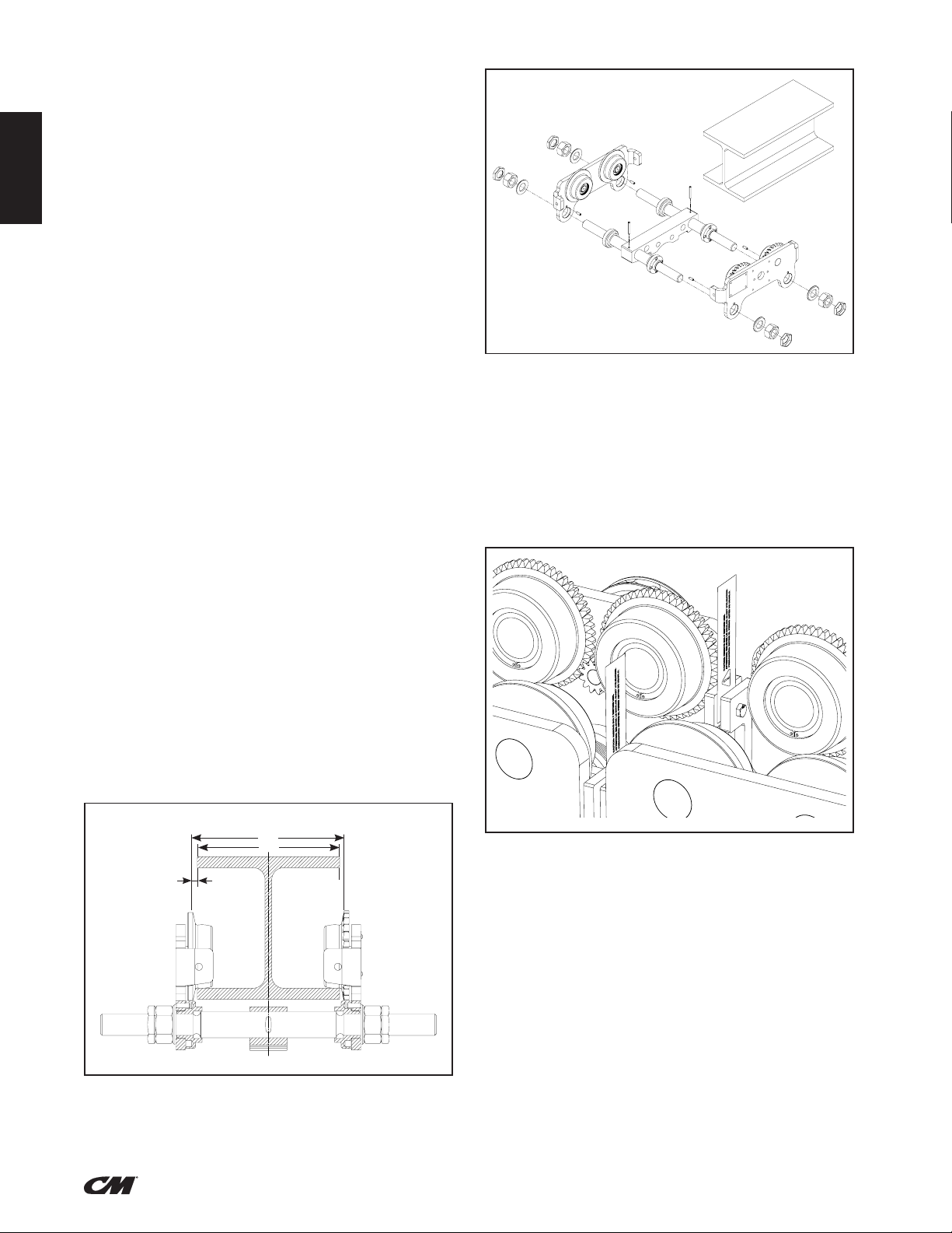
The railstops must be positioned so as to not exert impact force
on the hoist portion of the unit or the trolley wheels. They must
contact the ends of the trolley side frames. Due to the variations
in beam ange widths, it is suggested that the beam ange width
be measured to determine the necessary trolley ange width
adjustment. The distance between trackwheel anges (dimension
“X”) should be 1/8 to 3/16 inch greater than the beam ange width
for straight runway beams, and 3/16 to 1/4 inch greater than the
beam ange width if runway system includes sharp curves.
INSPECTION OF THE ATTACHMENT POINT
The attachment point for the hoist must be selected so that the
supporting structure to which it is to be tted has sufcient stability
and to ensure that the expected forces can be safely absorbed. The
unit must align freely also under load in order to avoid impermissible
additional loading. The selection and calculation of the appropriate
supporting structure are the responsibility of the operating company.
INSTALLING THE TROLLEY UP TO 5 TONNES
(5000 KG)
The trolleys are built to t beam range A or B which is indicated
on the identity plate. Before installation, make sure that the track
beam width is within this beam range. The further procedure for
assembly of the unit on the track beams depends on whether the
track beam has an accessible open end or not. If the beam has an
open end, it is recommended that the unit be preassembled on the
ground and then be pushed onto the open end of the beam.

ENGLISH
7
(ENGLISH) P/N 192048551 Rev. AA (January 2018)
Figure 4 - Trolley Installation
INSTALLING THE TROLLEY, 10 - 20 TONNES
(10000 KG - 20000 KG)
1. 15 and 20 tonne Integrated Trolley units are shipped from the
manufacturer with both trolleys connected by a bolt through the
bumper mounting holes. There is one bolt on each side. These
bolts must be removed before operation. Failure to do so can
affect wheel contact with beam and trolley performance on curved
beams. See Figure 5 for details.
2. Measure the ange width of the beam.
Figure 5 - Warning Tag
3. Evenly distribute the spacer sleeves and spacer washers on
both sides of the suspension bolt accordingly. A clearance of
2 mm between the wheel ange and the beam ange must be
maintained (inner dimension = ange width + 4 mm).
4. After adjustment of the inner dimension, evenly distribute the
remaining spacer sleeves and spacer washers on the outside
of the side plates on the suspension bolt. In each case, at least
3 spacer washers and 1 spacer sleeve must be mounted between
the side plates and the castle nut.
Tip: For easier assembly, tighten one side plate. Observe the
required position of the drive side. Only slide on the other side
plate without tightening.
5. Then lift the entire unit onto the track beam and rmly
tighten all castle nuts.
6. Secure all castle nuts with cotter pins.
1. Unscrew locking nuts (10) and hexagonal nuts (9) from
the suspension bolt (1) and remove both side plates (2)
from the trolley.
2. Measure ange width "b" of the track beam. See Figure 3.
3. Adjust or pre-adjust dimension "B" between the outer anges
of the round nuts (6) on the four free threaded ends of the
suspension bolts (1). Make sure that the four drill holes in the
round nuts face outwards. Select dimension "B" between the
outer anges of the round nuts on the suspension bolts in such
a way that it corresponds to ange width "b" plus 4 mm. Ensure
that the suspension bar (4) is centered between the round nuts (6).
4. Assembly of one side plate: The roll pins (7) tted to the side
plate (2) must be seated in one of the four drill holes of the
round nuts (6). If necessary the position of the round nuts
must be slightly re-adjusted.
5. Position the washer (8) and tighten the hexagonal nuts (9).
Finally screw on the locking nuts (10) by hand and tighten
by 1/4 to 1/2 rotation.
ATTENTION: THE LOCKING NUTS (10) MUST
ALWAYS BE FITTED!
6. Place the second side plate onto the suspension bolts without
tightening. Then screw on washers (8), hexagonal nuts (9) and
locking nuts (10) without tightening to facilitate assembly.
7. Place the entire pre-assembled unit onto the beam.
ATTENTION: PAY ATTENTION TO THE POSITION
OF THE GEAR DRIVE (5).
8. Insert the roll pins (7) driven into the second side plate in
one of the appropriate four drill holes of the round nuts (6).
If necessary the round nuts must be slightly re-adjusted.
9. Tighten the hexagonal nuts (9) on the second side plate.
Finally screw on the locking nuts (10) by hand and tighten
by 1/4 to 1/2 rotation.
ATTENTION: THE LOCKING NUTS (10) MUST
ALWAYS BE FITTED!
10. Check the tted unit:
• The lateral play dimension "A" must not exceed 2 mm
between the wheel ange (3) and the outer edge of
the beam.
• The suspension bar (4) must be positioned centrally
between the side plates.
• All nuts (9) and locking nuts (10) must be rmly tightened.
Figure 3 - Trolley Installed on I-Beam
b
B
A

ENGLISH
8
(ENGLISH) P/N 192048551 Rev. AA (January 2018)
ATTENTION: A TROLLEY MUST NEVER BE USED ON
A BEAM WITH A FLANGE WIDTH THAT EXCEEDS
THE MAXIMUM ADJUSTABLE WIDTH OF THE
TROLLEY (OBSERVE TOTAL CLEARANCE OF 5 MM,
DEPENDS ON MODEL) OR WITH A PROFILE WHICH
DOES NOT CORRESPOND TO THE PROFILE THE
TROLLEY HAS BEEN
DESIGNED FOR.
SHORTEN OR EXTEND THE HAND CHAIN
Adjust the length of the hand chain so that the distance of the lower
end to the oor is between 500 – 1000 mm.
NOTE
For safety reasons, hand chain links may only be used once.
• Look for the non-welded link of the hand chain, bend to open
and discard it.
• Shorten or extend the chain to the required length.
ATTENTION: ALWAYS REMOVE OR ADD AN EVEN
NUMBER OF CHAIN LINKS.
• Use a new link to close the loose chain ends by bending it
(for extending the hand chain, two new chain links are required).
ATTENTION: MAKE SURE THAT HAND CHAINS
ARE NOT TWISTED WHILE THEY ARE FITTED.
Immediately after installation, operate trolley with a capacity load
over the entire length of runway or monorail system to be sure that
all adjustments and operations are satisfactory.
When applying a load, it should be directly under the trolley.
Avoid off center loading of any kind. Side loading may spread
trolley side frames.
On systems with curves, the edges of the rail at the curved sections
should be lightly lubricated with grease.
If washer spacing recommendations are not followed, trolley hoist
may fall from beam.
TO AVOID INJURY:
Measure the actual beam ange on which the trolley hoist is to
operate and use Figure 3 to determine the arrangement of the
spacer washers for that ange width.
An excessively worn beam ange may fail and allow the trolley
hoist to fall from the beam.
TO AVOID INJURY:
Periodically inspect the beam ange for wear. Replace beam if
ange is worn.
INSPECTION
To maintain continuous and satisfactory operation, a regular
inspection procedure must be initiated to replace worn or damaged
parts before they become unsafe. Inspection intervals must be
determined by the individual application and are based on the type
of service to which your hoist will be subjected and the degree
of exposure to wear, deterioration or malfunction of the critical
components. As a minimum, a monthly inspection of the suspension
plate, trackwheels and pin nuts should be carried out.
The type of service to which the hoist is subjected can be classied
as “Normal”, “Heavy” and “Severe”.
Normal Service. Involves operation with randomly distributed loads
within the rated load limit, or uniform loads less than 65% of rated
load for not more than 25% of the time.
Heavy Service. Involves operating the hoist within rated load limit
which exceeds normal service.
Severe Service. Is normal or heavy service with abnormal operating
conditions.
Following are the recommended, minimum intervals of inspection.
When the unit is subjected to extra heavy usage or dusty, gritty,
moist, or other adverse atmospheric conditions, shorter time
intervals must be assigned. During the Periodic Inspection,
inspection must be made of all parts for unusual wear, corrosion
effect or damage in addition to those specically mentioned.
MINIMUM INSPECTION SCHEDULE
Frequent Inspections. These inspections are visual examinations
by the operator or other designated personnel. Records of such
inspections are not required. The frequent inspections are to be
performed monthly for normal service, weekly to monthly for heavy
service, and daily to weekly for severe service and they should
include those items listed in the hoist installation manual (P/N 656).
Periodic Inspections. These inspections are visual inspections of
external conditions by an appointed person. Records of periodic
inspections are to be kept to provide the basis for continuing
evaluation of the condition of the hoist.
Periodic inspections are to be performed yearly for normal service,
semi-annually for heavy service and quarterly for severe service
and they are to include those items listed in hoist installation
manual (P/N 656).
Any parts that are deemed unserviceable are to be replaced with
new parts before the unit is returned to service. It is very important
that the unserviceable parts be destroyed and properly disposed of
to prevent their possible future use as a repair item.
REPAIR PARTS LIST
Using "commercial" or other manufacturer's parts to repair the
CM Hurricane 360 Integrated Trolley may cause load loss.
TO AVOID INJURY:
Order all replacement parts from CM. Some parts may look alike
but often CM parts are made of specic materials or processed to
achieve specic properties.
ORDERING INSTRUCTIONS
The following information must accompany all correspondence
orders for replacement parts:
1. Serial number of trolley (two letters stamped on the
identication plate).
2. Capacity of trolley from nameplate.
3. Part name from parts list.
4. Part number and key number of part from parts list.
5. Quantity of parts required.
Parts should be ordered from CM's authorized Master Parts Depot
conveniently located throughout the United States and Canada.
Refer to www.cmworks.com to locate the Master Parts Depot
nearest you.

ENGLISH
9
(ENGLISH) P/N 192048551 Rev. AA (January 2018)
18
Explosionszeichnung/Explosion drawing/Vue éclatée YLITG 0,5 t/1 / 1,0 t/1 / 2,0 t/1
Haspelfahrwerk/Geared trolley/Commande de déplacement à aspe
FIGURE 6: PUSH AND GEARED TROLLEY 0.5 TONNE - 2 TONNE

ENGLISH
10
(ENGLISH) P/N 192048551 Rev. AA (January 2018)
Ref Description
Capacity
Qty.
0,5 t Single Reeved 1,0 t Single Reeved 2,0 t Single Reeved
1 Side Plate, Geared Wheel Side 00550133 00559089 00550137 1
2 Side Plate, Plain Wheel Side 00550135 00559096 00550139 1
3Load Bar, Flange Width A 00552000 00552002 00552004 2
Load Bar, Flange Width B 00552001 00552003 00552005 2
4 Nut 00559083 00559090 00559146 4
5Track Wheel, Plain 00508207 00508207 00508208 2
6Track Wheel, Geared 00508211 00508211 00508212 1
7* Driving Pinion, Handwheel Assembly - - - 1
8* Bearing Block, Handwheel Assembly - - - 1
9* Hand chain wheel - - - 1
10* Hand chain guide - - - 1
11 Retaining ring 09129029 09129029 09129025 4
12 Bearing 09151074 09151074 09151011 4
13 Retaining ring 09130024 09130024 09130027 4
14 Self-locking Counter Nut 09115151 09115152 09115153 4
15 Hex Nut 09115081 09115089 09115803 4
16 Washer 09121115 09121021 09121146 4
17 Spring pin 09134067 091340055 09134057 4
18* Screw, Handwheel Assembly - - - 2
19* Washer, Handwheel Assembly - - - 2
20 Bolt 00550129 00550119 00550141 1
21 Name Plate, Geared Trolley* 00550259 00550259 00550259 1
21 Name Plate, Plain Trolley 192038987 192038987 192038987 1
22 Round head grooved pin 09128004 09128004 09128004 4
23 Spring Pin, Handwheel Assembly - - - 1
24* Hand Chain, Handwheel Assembly 04307654 04307654 04307654 As Req**
25* Connecting Link, Handwheel Assembly 04307654CZPB 04307654CZPB 04307654CZPB 1-2
26 Spring pin 09134058 09134074 09134084 2
27 Middle bar 00550130 00550126 00550140 1
28 End cover 00400725 00400724 00400728 2
29* Handwheel and Gear Kit, Geared Trolley (includes
7, 8, 9, 10, 19, 18 and 23) 192039060 192039061 192039062 1
*These items only required on Geared Trolley Hoists. These items included in Handwheel and Gear Kit for Geared Trolleys. See table above.
**Please inform Customer Service of requested hand chain drop length. Actual chain length will be 2 x (Drop Length) + 0.72 ft
FIGURE 6: PUSH AND GEARED TROLLEY 0.5 TONNE - 2 TONNE

ENGLISH
11
(ENGLISH) P/N 192048551 Rev. AA (January 2018)
20
Explosionszeichnung/Explosion drawing/Vue éclatée YLITG 3,0 t/1 / 5,0 t/2
Haspelfahrwerk/Geared trolley/Commande de déplacement à aspe
FIGURE 7: PUSH AND GEARED TROLLEY 3 TONNE - 5 TONNE

ENGLISH
12
(ENGLISH) P/N 192048551 Rev. AA (January 2018)
Ref Description
Capacity
Qty.
3,0 t Single Reeved 5,0 t Single Reeved
1 Side Plate, Geared Wheel Side 00550145 00550149 1
2 Side Plate, Plain Wheel Side 00550146 00550151 1
3Load Bar, Flange Width A 00552006 00552008 2
Load Bar, Flange Width B 00552007 00552009 2
4 Nut 00559157 00559168 4
5Track Wheel, Plain 00508209 00508210 2
6Track Wheel, Geared 00508213 00508214 2
7* Driving Pinion, Handwheel Assembly - - 1
8* Bearing Block, Handwheel Assembly - - 1
9* Hand chain wheel - - 1
10* Hand chain guide - - 1
11 Retaining ring 09129002 09129003 4
12 Bearing 09151046 09151079 8
13 Retaining ring 09130046 09130060 4
14 Self-Locking Counter Nut 09115154 09115155 4
15 Hex Nut 09115090 09115156 4
16 Washer 09121016 09121213 4
17 Spring pin 09134054 09134120 4
18* Screw, Handwheel Assembly - - 2
19* Washer, Handwheel Assembly - - 2
20 Bolt 00550147 00550147 1
21 Name Plate, Push Trolley 192038987 192038987 1
21 Name Plate, Geared Trolley* 00550259 00550259 1
22 Round head grooved pin 09128004 09128004 4
23* Spring Pin, Handwheel Assembly 09134052 09134052 1
24* Hand Chain, Handwheel Assembly 04307654 04307654 As Req*
25* Connecting Link, Handwheel Assembly 04307654CZPB 04307654CZPB 1-2
26 Spring pin 09134084 09134047 2
27 Middle bar 00550142 00550128 1
28 End cover 00400733 00400733 2
29* Handwheel and Gear Kit, Geared Trolley (includes 7, 8, 9, 10,
19, 18 and 23) 192039063 192039064 1
*These items only required on Geared Trolley Hoists. These items included in Handwheel and Gear Kit for Geared Trolleys. See table above.
**Please inform Customer Service of requested hand chain drop length. Actual chain length will be 2 x (Drop Length) + 0.72 ft
FIGURE 7: PUSH AND GEARED TROLLEY 3 TONNE - 5 TONNE

ENGLISH
13
(ENGLISH) P/N 192048551 Rev. AA (January 2018)
22
Explosionszeichnung/Explosion drawing/Vue éclatée YLITG 10,0 t/3
Haspelfahrwerk/Geared trolley/Commande de déplacement à aspe
FIGURE 8: GEARED TROLLEY 10 TONNE

ENGLISH
14
(ENGLISH) P/N 192048551 Rev. AA (January 2018)
Ref Description
Capacity
Qty.
10,0 t Single Reeved
1 Side Plate, Plain Wheel Side 00530004 1
2 Side Plate, Geared Wheel Side 00530005 1
3 Load Bar, Flange Width B 00530009 1
4 Spacer Sleeve 00530010 2
5Spacer Washer, Thick 00530011 6
6Spacer Washer, Thin 00530012 16
7 Brace 00530025 2
8Track Wheel, Plain 00530006 2
9Track Wheel, Geared 00530007 2
10 Driving Pinion, Handwheel Assembly - 1
11 Bearing Block, Handwheel Assembly - 1
12 Hand chain wheel - 1
13 Hand chain guide - 1
14 Groove ball bearing 09150020 8
15 Retaining ring 09129010 4
16 Cap 00530008 4
17 Retaining ring 09130009 4
18 Castle nut 00530014 2
19 Washer 00530013 6
20 Cotter pin 09125035 2
21 Screw, Handwheel Assembly - 2
22 Lockwasher, Handwheel Assembly - 2
23 Name plate 00508223 1
24 Capacity plate 00407702 1
25 Round head grooved pin 09128004 6
26 Spring Pin, Handwheel Assembly - 1
27 Hand Chain, Handwheel Assembly 004307654 As Req*
28 Connecting Link, Handwheel Assembly 00404733 1-2
29 Suspension lug 00401078 1
30 Handwheel and Gear Kit, Geared Trolley (includes 10, 11, 12, 13, 21, 22, 26) 192047895 1
* Please inform Customer Service of requested hand chain drop length. Actual chain length will be 2 x (Drop Length) + 0.72 ft
FIGURE 8: GEARED TROLLEY 10 TONNE

ENGLISH
15
(ENGLISH) P/N 192048551 Rev. AA (January 2018)
24
Explosionszeichnung/Explosion drawing/Vue éclatéeYLITG 20,0t/6
Haspelfahrwerk/Geared trolley/Commande de déplacement à aspe
FIGURE 9: GEARED TROLLEY 15 TONNE - 20 TONNE

ENGLISH
16
(ENGLISH) P/N 192048551 Rev. AA (January 2018)
Ref Description
Capacity
Qty.
15,0 - 20,0 t Sextuple Reeved
1 Side Plate, Plain Wheel Side 00530004 2
2 Side Plate, Geared Wheel Side 00530005 2
3 Load Bar 00530009 2
4 Spacer Sleeve 00530010 4
5Spacer Washer, Thick 00530011 16
6Spacer Washer, Thin 00530012 32
7 Brace 00530025 4
8Track Wheel, Plain 00530006 4
9Track Wheel, Geared 00530007 4
10 Driving Pinion, Handwheel Assembly 00530016 1
11 Bearing Block, Handwheel Assembly 00530015 1
12 Hand chain wheel 00558061 1
13 Hand chain guide 00558062 1
14 Groove ball bearing 09150020 16
15 Retaining ring 09129010 8
16 Cap 00530008 8
17 Retaining ring 09130009 8
18 Castle nut 00530014 4
19 Washer 00530013 12
20 Cotter pin 09125035 4
21 Screw, Handwheel Assembly 09101038 2
22 Lockwasher, Handwheel Assembly 09122016 2
23 Name plate 00508223 1
24 Capacity plate 00407704 1
25 Blind rivet 09128004 6
26 Spring Pin, Handwheel Assembly 09134082 1
27 Hand Chain, Handwheel Assembly 004307654 As Req*
28 Connecting Link, Handwheel Assembly 04307654CZPB 1 - 2
29 Suspension Lug 00400941 2
30 Spacer Sleeve, Suspension Lug 00400942 2
* Please inform Customer Service of requested hand chain drop length. Actual chain length will be 2 x (Drop Length) + 0.72 ft
FIGURE 9: GEARED TROLLEY 15 TONNE - 20 TONNE

ENGLISH
17
(ENGLISH) P/N 192048551 Rev. AA (January 2018)
NOTES

ENGLISH
18
(ENGLISH) P/N 192048551 Rev. AA (January 2018)
NOTES

INDEMNIFICATION AND SAFE OPERATION
Buyer shall comply with and require its employees to comply with directions set
forth in instructions and manuals furnished by Seller and shall use and require its
employees to follow such instructions and manuals and to use reasonable care in
the use and maintenance of the goods. Buyer shall not remove or permit anyone
to remove any warning or instruction signs on the goods. In the event of personal
injury or damage to property or business arising from the use of the goods,
Buyer shall within 48 hours thereafter give Seller written notice of such injury
or damage. Buyer shall cooperate with Seller in investigating any such injury or
damage and in the defense of any claims arising therefrom.
If Buyer fails to comply with this section or if any injury or damage is caused,
in whole or in part, by Buyer’s failure to comply with applicable federal or state
safety requirements, Buyer shall indemnify and hold Seller harmless against any
claims, loss or expense for injury or damage arising from the use of the goods.
CMCO Warranty (HOISTS)
A. Columbus McKinnon Corporation (“Seller”) warrants to the original end user
(“Buyer”) that: (a) for a period of one (1) year from the date of Seller’s delivery of
the goods (collectively, the “Goods”) to the carrier, the electrical components of
the Goods will be free from defects in workmanship and materials; and (b) for
the life of the Goods, the mechanical components of the Goods will be free from
defects in workmanship and materials.
B. IN THE EVENT OF ANY BREACH OF SUCH WARRANTY, SELLER’S SOLE
OBLIGATION SHALL BE EXCLUSIVELY LIMITED TO, AT THE OPTION OF
SELLER, REPAIR OR REPLACEMENT, F.O.B. SELLER’S POINT OF SHIPMENT,
OF ANY GOODS THAT SELLER DETERMINES TO HAVE BEEN DEFECTIVE
OR, IF SELLER DETERMINES THAT SUCH REPAIR OR REPLACEMENT IS NOT
FEASIBLE, TO A REFUND OF THE PURCHASE PRICE UPON RETURN OF THE
GOODS TO SELLER. NO CLAIM AGAINST SELLER FOR ANY BREACH OF (i)
SUCH WARRANTY WITH RESPECT TO THE ELECTRICAL COMPONENTS OF
ANY GOOD SHALL BE VALID OR ENFORCEABLE UNLESS BUYER’S WRITTEN
NOTICE THEREOF IS RECEIVED BY SELLER WITHIN ONE (1) YEAR FROM THE
DATE OF SELLER’S DELIVERY TO THE CARRIER AND (ii) SUCH WARRANTY
WITH RESPECT TO THE MECHANICAL COMPONENTS OF ANY GOOD SHALL
BE VALID OR ENFORCEABLE UNLESS BUYER’S WRITTEN NOTICE THEREOF
IS RECEIVED BY SELLER WITHIN ONE (1) YEAR FROM THE DATE THE DATE
ANY ALLEGED CLAIM ACCRUES. EXCEPT FOR THE WARRANTY SET FORTH
ABOVE, SELLER MAKES NO OTHER WARRANTIES WITH RESPECT TO THE
GOODS, WHETHER EXPRESSED OR IMPLIED, INCLUDING ANY WARRANTIES
OF MERCHANTABILITY, FITNESS FOR A PARTICULAR PURPOSE, QUALITY
AND/OR THOSE ARISING BY STATUTE OR OTHERWISE BY LAW OR FROM
ANY COURSE OF DEALING OR USE OF TRADE, ALL OF WHICH ARE HEREBY
EXPRESSLY DISCLAIMED.
C. IN NO EVENT SHALL SELLER BE LIABLE TO BUYER OR ANY THIRD PARTY
WITH RESPECT TO ANY GOOD, WHETHER IN CONTRACT, TORT OR
OTHER THEORY OF LAW, FOR LOSS OF PROFITS OR LOSS OF USE, OR
FOR ANY INCIDENTAL, CONSEQUENTIAL, SPECIAL, DIRECT OR INDIRECT
DAMAGES, HOWSOEVER CAUSED. SELLER’S MAXIMUM LIABILITY TO
BUYER WITH RESPECT TO THE GOODS SHALL IN NO EVENT EXCEED THE
PRICE PAID BY BUYER FOR THE GOODS THAT ARE THE SUBJECT OF THE
APPLICABLE CLAIM.
D. Seller shall not be liable for any damage, injury or loss arising out of the use of
the Goods if, prior to such damage, injury or loss, such Goods are: (1) damaged
or misused following Seller’s delivery to the carrier; (2) not maintained, inspected,
or used in compliance with applicable law and Seller’s written instructions
and recommendations; or (3) installed, repaired, altered or modied without
compliance with such laws, instructions or recommendations.
E. This warranty is limited and provided only to the original end user. Each Good
must be registered within sixty (60) days of receipt of each product to
establish eligibility. Please register at www.cmworks.com/hoist-warranty-
registration or submit registration card via US mail.
F. Any action against Seller for breach of warranty, negligence or otherwise in
connection with the electrical components of any Good must be commenced
by Buyer within one (1) year after: (a) the date any alleged claim accrues; or
(b) the date of delivery of the Goods to Buyer, whichever is earlier. Any action
against Seller for breach of warranty, negligence or otherwise in connection
with the mechanical components of any Good must be commenced by Buyer
within one (1) year after the date any alleged claim accrues.
Alterations or modifications of equipment and use of non-factory repair
parts can lead to dangerous operation and injury.
TO AVOID INJURY:
• Do not alter or modify equipment.
• Do use only factory replacement parts.
LIMITATION OF WARRANTIES, REMEDIES AND DAMAGES
© 2017 Columbus McKinnon Corporation. All Rights Reserved.
USA: Ph: (800) 888.0985 •(716) 689.5400 •Fax: (716) 689.5644 • www.cmworks.com
CANADA: Ph: (877) 264.6478 •Fax: (877) 264.6477 •www.cmworks.com
WARRANTY
P/N 192048551 Rev. AA (January 2018)
This manual suits for next models
52
Table of contents
Other CM Chain Hoist manuals

CM
CM 622A Series User manual

CM
CM 653 Series User manual

CM
CM 646 Series User manual

CM
CM Lodestar D8 PLUS Installation and operating instructions

CM
CM Bandit BAN07505 User manual

CM
CM Shopstar User manual

CM
CM Hurricane Mini 360 User manual

CM
CM 653-A User manual

CM
CM 5623A User manual

CM
CM Lodestar A User manual
Popular Chain Hoist manuals by other brands

Come.up Winch
Come.up Winch APE-16 quick start guide

HADEF
HADEF 53/07 Installation, operating and maintenance instructions

Gis
Gis LPM Translation of the original instruction manual

GÜDE
GÜDE GEKZ 300 Original instructions

Ingersoll-Rand
Ingersoll-Rand LC2A015S Product information

POWERTEX
POWERTEX PCB-S2 user manual