2
GENERAL INF RMATI N
SPECIFICATI NS
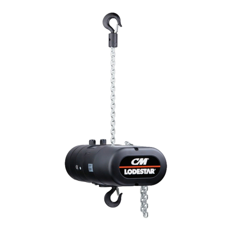
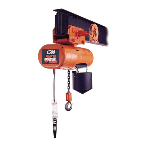
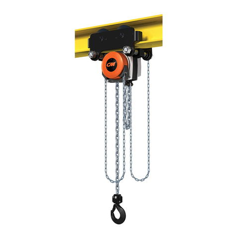
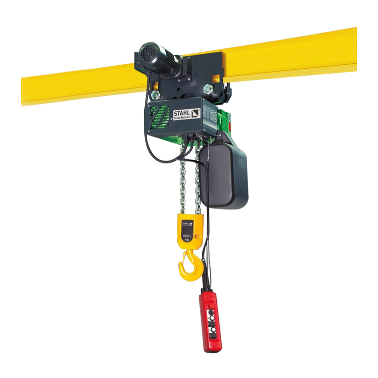
The Series 635 Motor Driven Trolleys are designed for use
with the Lodestar, and Valustar Electric Chain Hoists. The trol-
leys are available in two capacities: 1/8 through 2-Tons and
3-Tons. These trolleys are similar except for the sizes of the
load carrying members.
The trolleys have rugged steel side plates, hardened steel
axles, steel suspension bolts, cast iron load bracket from
which the hoist is suspended and hardened cast iron wheels
that are suitable for operation on sloped or flat flanged
beams. Hardened steel gears are attached to two track-
wheels and driven by a right angle worm gear reducer. The
worm and gear of the gear reducer operate in an oil bath.
A weatherproof motor drives the gear reducer.
The control box contains a reversing contactor, terminal
boards and a transformer (as required). A four-button control
station is suspended from the control box. An electric brake,
which fits between the motor and gear reducer, is available
as optional equipment.
Table 1 provides the general specifications for the trolley. t
should be noted that the table indicates that the standard travel
speed is 75 FPM. However, other travel speeds are available.
CM REPAIR/REPLACEMENT P LICY
All Columbus McKinnon (CM) Series 635 Motor Driven
Trolleys are inspected and performance tested prior to ship-
ment. f any properly maintained Series 635 Motor Driven
Trolley develops a performance problem, within 1 (one) year
of shipment, due to a material or workmanship defect, as ver-
ified by CM, repair or replacement of the unit will be made to
the original purchaser without charge. This
repair/replacement policy applies only to Series 635 Motor
Driven Trolleys installed, maintained and operated as out-
lined in this manual, and specifically excludes parts subject
to normal wear, abuse, improper installation, improper or
inadequate maintenance, hostile environmental effects and
unauthorized repairs/modifications.
We reserve the right to change materials or design if, in our
opinion, such changes will improve our product. Abuse,
repair by an unauthorized person, or use of non-CM replace-
ment parts voids the guarantee and could lead to dangerous
operation. For full Terms of Sale, see Sales Order
Acknowledgement. Also, refer to the back cover for
Limitations of Warranties, Remedies and Damages, and
indemnification and Safe Operation.
INSTALLATI N
UNPACKING INF RMATI N
After removing the trolley from the shipping carton, carefully
inspect the external condition of the cords, control box, gear
reducer, motor brake (if equipped with same) and motor for
damage that may have occurred during shipment and han-
dling. Check to make sure all parts (trolley side frame assem-
bly with control box, trolley side frame with gear reducer and
motor, load bracket, suspension bolts, spacer washer, cotter
pins and nuts) are furnished. Also, before attempting to
install the trolley, make sure that the power supply indicated
on the labels attached to the control box is the same as the
power supply on which the unit is to operate.
INSTALLATI N
The hoist, trolley and lug suspension for suspending the hoist
from the trolley are packed separately. Assemble the lug sus-
pension to the hoist according to the instructions furnished
with the suspension and/or the instructions in the manual fur-
nished with the hoist.
The stops must be positioned so as to not exert impact force
on the hoist frame or trolley wheels. They must contact the
ends of the trolley side frames.
Trolley to Beam
t is recommended that the trolley be mounted on the beam
prior to attaching the hoist to the trolley. Before attempting
to mount the trolley on the beam, measure the actual width
of the beam flange on which the trolley is to operate. Using
this measurement, determine the arrangement of the spac-
er washers using Figure 1 and Table 2. Chart A of Table 2
shows the washer arrangement for the 1/8 – 2-Ton trolley,
while Chart B provides data for the 3-Ton trolley. Loosely
assemble the side frames, load bracket, spacer washers
and nuts on the suspension bolts as shown in Figure 1.
WARNING
Operating the trolley on a beam that has no rail stops may
allow the trolley to fall off the end of beam.
T AV ID INJURY:
Install rail stops at each end of the beam on which the trolley
is to operate.
Series 635 Motor Driven Trolley Specifications
FOR USE RAVEL AADDJJUUSSTTMMEENNTT FFOORR SSTTDD.. SS BBEEAAMMSSMINIMUM APPROX.
DC CAPACI Y WI H POWER SPEED MO OR DEP H FLANGE RADIUS SHIPPING
CODE CODE ( ONS) MODELS SUPPLY* (FPM) H.P. (IN.) WID H (IN.) CURVE (IN.) WEIGH
3670 63670 1/8 A 115-1-60 6 3-3/8 103
3671 63671 to thru 230-3-60 75 1/4 thru thru 30 112
3672 63672 2 RR 460-3-60 15 5-5/8 112
9577 69577 115-1-60 64 130
9578 69578 3 RT-RRT 230-3-60 75 1/4 thru thru 30 130
9579 69579 460-3-60 15 5-5/8 130
Table 1
*Trolleys are also available for operation on 573-3-60 and 220/380-3-50 power supply systems.
LL
!!
For
more
information
contact:
Sievert
Crane
and
Hoist,
(708)
771-1600,
[email protected],
www.sievertcrane.com
