10 00001996 (REV AC) 627NH October 2014
INSTALLATION
UNPACKING INFORMATION
When received, the hoist should be carefully inspected
for damage which may have occurred during shipment or
handling. Check the hoist frame for dents or cracks, the
external cords for damaged or cut insulation, the control
station for cut or damaged enclosure, and inspect the
load chain for nicks and gouges. If shipping damage has
occurred, refer to the packing list envelope on the carton for
claim procedure.
Before installing the hoist, make sure that the power supply
to which it will be connected is the same as that shown on
the nameplate located on the side of the hoist.
NOTE: See Electrical Installation instructions
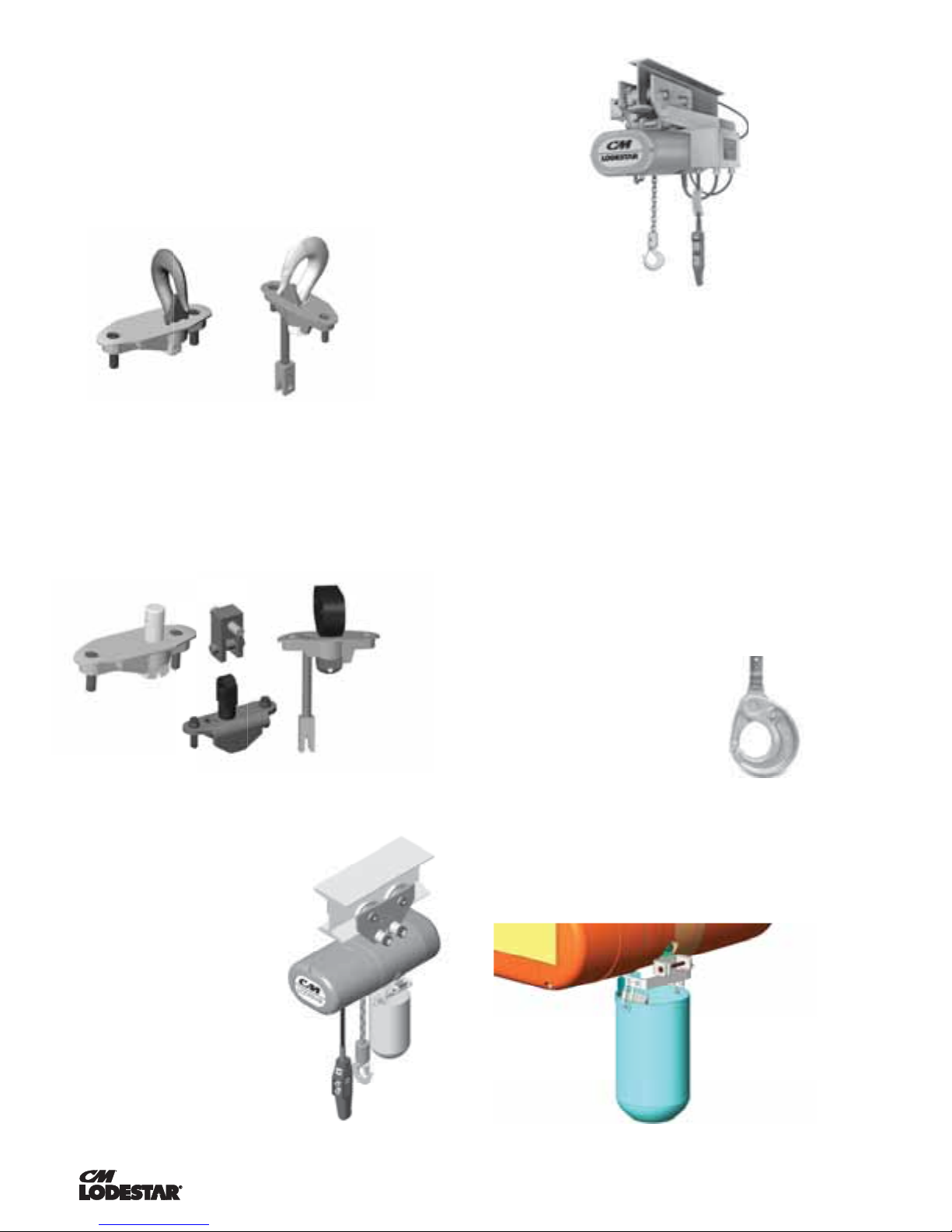
INSTALLING THE SUSPENSION
A. Single Reeved Units:
For Models A,B,C,F, J, JJ, L, & LL:
Remove the hook suspension and (2) suspension screws
from the packaging. Place the suspension assembly into the
recess on top of the hoist so that the adaptor body follows
the contour of the hoist. Insert the suspension screws
through the holes in the adapter and hand thread these into
the self-locking nuts enclosed in the hoist.
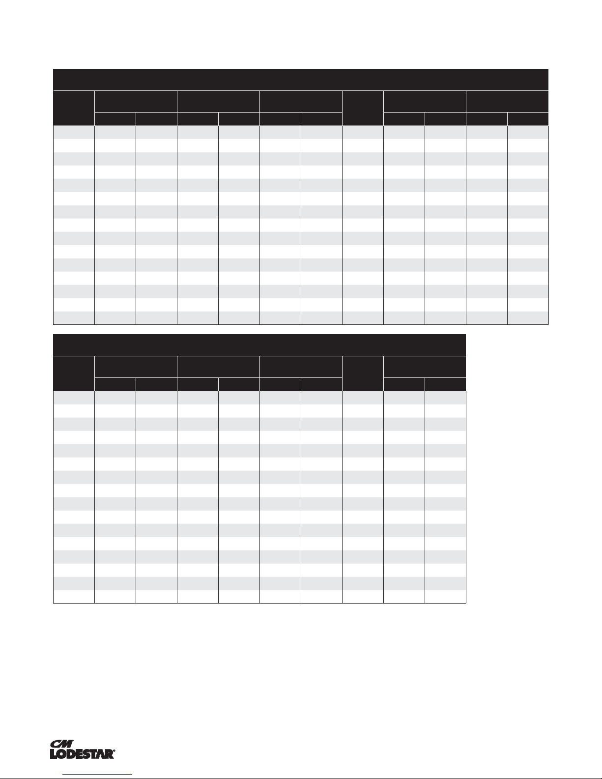
Securely tighten the screws to the recommended seating
torque (see Table 2) using a 12 point socket: 3/8" for Models
A, B, C, & F and 1/2" for Models J-LL.
For Model RRS:
Remove the hook suspension, screw and locknut from
the packaging. Slide the suspension assembly into the
channel in the top of the hoist. Insert the locknut into the
hex recess on the side of the suspension riser, insert the
screw through opposite side and hand thread the screw
into the self-locking nut.
Securely tighten the screw to the recommended torque (see
table 2), using a 3/16" hex bit socket.
Use of impact tools (electric or pneumatic) may cause premature failure
of attaching hardware.
B. Double Reeved Units:
Remove the hook suspension,(2) suspension screws,
(1) dead end pin, (1) washer, and (1) cotter pin from the
packaging. It should be noted that the suspension includes a
dead end bolt and block for supporting the dead end of the
load chain as shown in Figure 7.
Place the suspension assembly into the recess on top of
the hoist. The dead end block should project through the
bottom of the hoist with the pin hole and slot aligned to the
underside of the hoist as shown in Figure 7. If these are
not aligned as shown, lift the head of the bolt from the hex
recess in the adapter and turn the bolt and block assembly
and reseat the bolt head to obtain the proper alignment. Do
not change the position of the dead end block on the bolt to
attain this alignment.
Check the position of the pin hole in the dead end block to
make sure it has not been disturbed from its factory setting.
The distance from the top of the pin hole to the bottom of the
hoist should not exceed 1/4" (6.35mm) for Models E,E-2, H,
H-2 and 7/16" (11.11mm) for Models R, R-2, RR, RR-2. If the
distance is not correct, adjust the position of the dead end
block to obtain the proper distance (see fig. 21, p 73.)
Now, insert the suspension screws through the holes in the
adapter and hand thread these into the self-locking nuts
enclosed in the hoist frame. Securely tighten the screws to
the recommended seating torque (see Table 2) using a 12
point socket: 3/8" for Models E & H and 1/2" for Models R &
RR.
The dead end of the load chain is temporarily positioned ( a
few links from the end) by a wire tie. Do not remove this tie
before attaching the chain to the dead end block. (See Fig. 7)
C. Triple Reeved Units:
These hoists have a sheave hanger which is loosely
connected to the top of the frame by a thin metal plate for
shipping purposes. To attach the suspension, support the
sheave hanger from the underside of the hoist and remove
the nut and seat from the sheave stud. Remove and discard
the shipping plate and retain the sheave stud nut and seat
since they will be reused later.
Remove the suspension assembly from the carton and the
two suspension screws. Place the suspension assembly over
the sheave stud and into the recess on top of the hoist. Insert
the suspension screws through the holes in the suspension
adapter and hand thread these into the self-locking nut
enclosed in the hoist. Securely tighten the screws to the
recommended seating torque (see Table 2) using a 12 point,
1/2" socket.
After the suspension assembly is installed, secure the sheave
stud to the suspension adapter using the round slotted nut
and seat that were formerly used to attach the shipping plate
to top of the hoist frame. Place the seat over the stud with
the flat side down and then rotate the seat so that there is
clearance between the seat and the suspension lug or hook.
Assemble the nut to the stud and turn the nut by hand until
the nut seats in the seat and the sheave hanger is snug in
the frame. Then back off the nut until the hole in the stud is
in line with one of the slots in the nut. Using a hammer, drive
the retaining pin (packed with the suspension assembly) into
the hole in the sheave stud until the end of the pin is flush
with the edge of the nut.
Using other than CM supplied high strength suspension screws to
attach the suspension adapter to the hoist may cause the screws to
break and allow the hoist and load to fall.
TO AVOID INJURY:
Use only the CM supplied suspension screws to attach the
suspension to the hoist and hand torque these screws to the
recommended seating torque as specified in tables 2a and 2b. DO
NOT apply any type of lubricant to the threads of these screws.
Lubricating the threads will reduce the effort to seat the screws
and as a result, tightening the screws to the above recommended
torque may break the screw,damage the suspension adapter, strip
the nuts and/or damage the hoist frame.
SUSPENSION BOLT SHOULD BE REPLACED ANY TIME
THE SUSPENSION IS REMOVED FROM THE HOIST