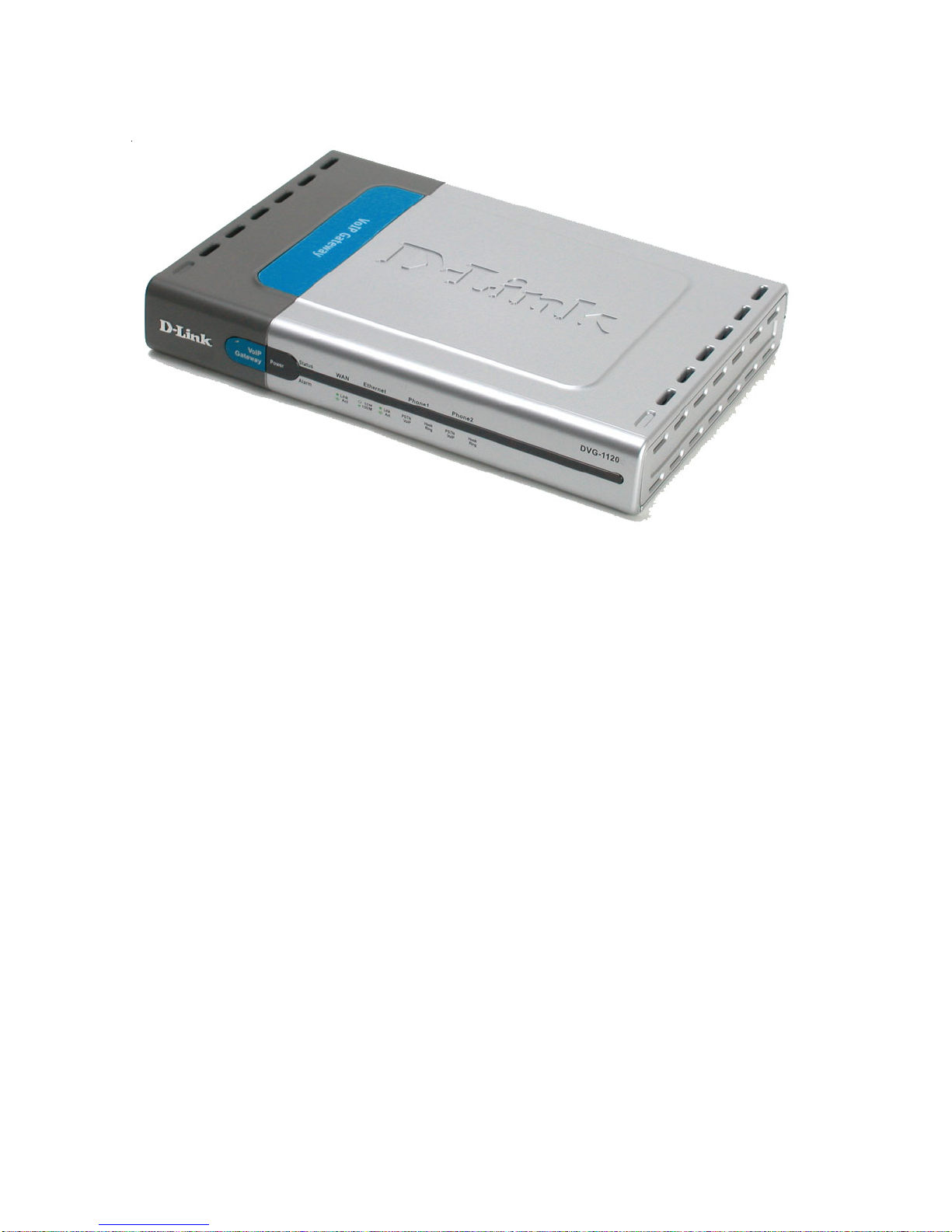
D-Link DVG-1120S - VoIP Gateway/Router With 1 LAN... User manual

VoIP Residential Gateway
with Two Voice Ports
Manual
Building Networks for People
D-Link
DVG-1120S

2
Contents
PackageContents ................................................................................3
Introduction............................................................................................4
Connections..........................................................................................5
Features andBenefits ...........................................................................6
LEDs ....................................................................................................7
Web-basedManagement......................................................................8
ConfigurationUsing aConsole............................................................35
Usingthe ConsolePort .......................................................................40
CommandLineInterface .....................................................................46
NetworkingBasics ..............................................................................54
TechnicalSpecifications ......................................................................69
ContactingTechnicalSupport ..............................................................72
Warranty..............................................................................................73
Registration ........................................................................................76

3
Contents of Package:
D-Link DVG-1120S
VoIP Residential Gateway with Two Voice Ports
A/C PowerAdapter
ManualonCD
QuickInstallationGuide
If any of the above items are missing, please contact your reseller.
System Requirements For Configuration:
Package Contents
At least 128 MB of memory and a 500 MHz processor
Computer with Windows, Macintosh, or Linux-based operating
system with an installed Ethernet adapter
Internet Explorer or Netscape Navigator version 4.0 or above,
with JavaScript enabled
Note:Usingapowersupplywithadifferentvoltageratingthantheoneincludedwith
theDVG-1120S will cause damage and void the warranty for this product.

4
Introduction
TheD-LinkDVG-1120SVoIPStationGatewaylinkstraditionaltelephonenetworks
to IP networks with conventional telephone devices such as analog phones or
fax machines.
The DVG-1120S includes two Foreign Exchange Subscriber (FXS) interfaces
with normal RJ-11 telephone connectors that provide voice/fax communication
over the IP network.
Two Ethernet ports are also provided. One Ethernet port is for a DSL/Cable
Modem or other WAN device, and the other is for connection to create a home
or small office LAN network.
The built-in DHCP server and Network Address Translation (NAT) function
automatically assigns IP addresses for LAN users, allowing multiple users to
share a single Internet connection. You can configure and monitor the DVG-
1120S via the Console or the Web browser. Telnet and SNMP management is
also supported.
Byroutingcalls over the Internetorany IPnetwork, the DVG-1120S can reduce
or eliminate long distance or inter-office phone charges. Corporations can also
enjoy the benefits of network consolidation and reduction of leased lines by
relying on the Internet service providers to deliver toll-quality voice
communications over the IP networks.

5
RESET
CONSOLE ETHERNET
VoIP WA N LINE1
PSTN
12V 1A 2
Connections - Back Panel of Unit
AC Power Connector Use the
includedpoweradapter.Ifyouuse
a power adapter other than the
oneincluded with the productyou
will damage the device and void
the warranty on this product.
PSTN/VoIP
Switch to
select PSTN
or VoIP mode
When the
switch is in
the down
position,
Phone1/2 will
bein VoIP
Mode.
When the
switch is in
the up
position,
Phone1/2 will
be configured
to PSTN
Mode.
Reset Switch Used to return the device
to its original configuration. This is the
same as performing a factory reset.
Diagnostic Port An RJ-14
port used to configure the
device. (User needs a RJ-
14 to RS-232 converter).
Plug one end of a straight-
through wired RJ-14 cable
to the device and the other
end to a serial port of a PC
running a terminal
emulation program (such
as Microsoft HyperTerminal)
or a VT-100 terminal.
Phone 1 to 2
Normal RJ-11 phone
jacks used to
connect telephones
and fax machines.
Plug your normal
telephone(s) and/or
fax machine directly
into any of these
jacks.
Line RJ 11 phone
jack for connecting
to a standard
telephonewalloutlet
throughan
approved (No. 26
AWG or larger)
telecommunications
line cord.
Ethernet
WAN A
10Mbps
Ethernet port
fitted with an
RJ-45
connector
used to
connect the
VoIPgateway
to a WAN
device(e.g.
Cable/ADSL
Modem). This
port accepts
Category 3, 4
or 5 UTP
cabling with
an RJ-45
connector.
Ethernet LAN
A10/100Mbps
dual-speed
Fast Ethernet
port fitted with
an RJ-45
connector
used to
connect the
VoIPgateway
toaLAN
device(hub,
switch, PC,
etc.). This port
accepts
Category 5 or
betterUTP
cabling with
an RJ-45
connector.
Warning! Using a different power adapter than the
oneincludedwithyour purchase will damagethe
DVG-1120Sand voidthewarranty.

6
Two analogFXS interface portsaccepting RJ-11connectors to facilitate
two VoIP connections
One analog POTS interface for PSTN Life Line (standard phone line)
One 10Mbps WAN port for connecting to a DSL/Cable Modem or other
WAN devices
One 10/100Mbps LAN port for connecting to a local network
IP address assignment using DHCP (Dynamic Host Configuration
Protocol) or static configuration
IP Routing support (RIP1, RIP2 and Static Routing)
Remote software download/update
Supports IP sharing to allow multiple users to access the Internet via a
single IP address
Built-in PPPoE function to support dial-up connection for broadband
technology
Supports Caller ID
Supports QoS to guarantee voice quality
Automatic Call Redirection (ACR) function support
PSTN or VoIP line automatic selection (e.g. 110, 119)
PSTN/ VoIP routing table support
Call will automatically redirect to PSTN in case of getting the
“4xx, 5xx and 6xx” error message from SIP server.
Life Line support
Automatic fall back to PSTN mode in case of power failure
PSTN/VoIPline selection manually (VoIP/PSTN Callalternation
via configurable prefix number)
Listening of incoming call from PSTN
Features & Benefits

7
DVG-112 0M
WAN
VoIP
Gateway
Status
Power
Phone1 Phone2Ethernet
Alarm
LEDS - Front Panel of Unit
Ethernet This LED displays the
connection speed, link status, and
activity on the 10/100 dual-speed
Ethernet port that is used to connect
toyour LAN.
10/100M - This indicator remains
unlit when there is no connection,
or the port is operating at 10Mbps
throughaconnectionto a10BASE-
T device. It is lit when the port is
operating at 100Mbps through a
connection to a dual-speed or
100BASE-TX Fast Ethernet
device.
Link/Act - When a good link to a
powered-up but idle device is
detected on a port, this indicator
shines steadily. When packets are
received from the device, the
indicator blinks off and on.
WAN This LED displays the
link status and activity on the
10MEthernetport thatisused
to connect to your WAN
device (usually a Cable or
ADSLModem). When agood
link to a powered-up but idle
device is detected on a port,
the WAN indicator shines
steadily. When packets are
received from the device, the
indicator blinks off and on.
Phone 1 to 2 This LED displays
the PSTN status and Hook/
Ringingactivity on theRJ-11 port
that is used to connect to your
normaltelephone(s)/fax machine
and PSTN line.
Power This LED is lit when
the device is receiving
power; otherwise, it is unlit.
Status/Alarm This LED will remain
dark when the CPE is either
performing a self-test/booting up or
not registered to the SIP server. The
LED will remain green when the
system is already registered to the
SIP server. It will flash slowly during
registration, until all ports have been
registered.
PSTN/VoIP - Lights when
PSTN line is in use. It is dark
during VoIP communication.
Hook/Ringing - When an off-
hook action is detected on a
phoneport,thisindicatorshines
steadily. When a ringing signal
isreceived fromthedevice, the
indicator blinks off and on.
DVG-1120S

8
Web-based Management
In order to use a web browser to configure the VoIP gateway, you must make
sure it has a valid Ethernet connection to a PC or LAN via its LAN port.
Accessthe configurationutility tocheckthe LANport by enteringtheIPAddress
into your web browser address field.
Initially,the VoIP
gateway does not have
a Username or
Password. To log in,
simply click on the OK
button.
Afterloggingin,the
Device Info screen on
the following page will
be displayed.
Click on Login to the
Web-based
Management
module.
192.168.15.1
Type 192.168.15.1
(the IPAddress) into
the address field of
your browser. http://192.168.15.1

9
Web-based Management (continued)
Setting Up the Connection
TheVoIPgateway’sWANportcomes
with DHCP as the default IP setting.
If the VoIP gateway cannot get the
assigned DHCP IP, it will use the
manualIP (defaultis10.1.1.1 )asit’s
defaultIP.
To configuretheWAN port,pleasedo the following:
Then go to Start>Control
Panel>Network
Connections>Right-click local
area connection >select
Properties> double click Internet
Protocol (TCP/IP). The screen at
right will appear.
Make sure the PC is in the same IP
domain as the VoIP gateway. You
can do this by changing the IP
Address of the PC as shown here.
Click on Config WAN IPAddress.
Manually input the
WAN IPAddress here.

10
Web-based Management (continued)
Config IP - Config WAN IP Address
IPAddress - Enter a WAN port IPAddress for the VoIP gateway.
Subnet Mask -Enter a WAN port subnet mask for the VoIP gateway.
Default Gateway - Enter the IPAddress of the WAN devices you are
using to make the WAN connection.
Host Name - This is a user-defined host name for this VoIP Gateway.
DNS1 Server IP - Enter the IP Address of the first DNS Server.
DNS2 Server IP - Enter the IP Address of the second DNS Server.
User Name - Enter the User Name for the PPPoE function.
Authentication Password - Enter the Password for the PPPoE function.
Confirm Password - Enter the Password again for confirmation.
More WAN IP
Configuration
settings include:
Manual -When
Manual is
chosen, the
VoIP gateway will obtain its IP settings from the fields located just
below.
BOOTP -When BOOTP is chosen, the VoIP will attempt to obtain
its IP settings from a BOOTP server located on your WAN.
DHCP -When DHCP is chosen, the VoIP will attempt to obtain its IP
settings from a DCHP server located on your WAN.
PPPoE -When PPPoE is chosen, the VoIP will attempt to obtain its
IP settings through PPPoE on your WAN.
Get IP From -
Choose the method
that theVoIPgateway
will use to obtain its
IP settings once it is
restarted. Choices
include:

11
Web-based Management (continued)
Config IP – Config LAN IP Address
Device Information
LAN IP Address -
Enter a LAN IP
Address for the
VoIPgateway.
LAN Netmask -
EnteraLAN
netmask for the
VoIPgateway.
Click Save to save
the settings.
Device Type - The
model name of this
device.
MAC Address - The
MAC address of this
device.
Boot PROM
Version - The
version number of
the device’s startup
code.
Firmware Version -
The version number of the device’s runtime code.
DSP Version - The Digital Signal Processor version, if any.
Serial Number - A user-determined identification number.
System Name - A user-defined name for this device.
Country Code - Auser-defined country code for this device. < 0:USA
(Default), 1:Japan, 2:Hong Kong, 3:Sweden, 4:China>
Web Port Number- A user-defined web port number. (From 1024 to
29999, and 80)
Click Save to save the settings.

12
Web-based Management (continued)
Proxy DNS
State - Enables or disables the Proxy DNS function.
Proxy DNS IP Address - Enter the Proxy DNS IPAddress.
Click Save to save the settings.

13
Web-based Management (continued)
Telephony Configuration
Signaling ToS - Set
the Type of Service
value for VoIP
signaling
RTP ToS - Set the
Type of Service
value for RTP
packets
Receive Gain - Set
theReceivegainofthe
device. (-14 to +14
dB)
Transmission Gain - Set the Transmit gain of the device. (-14 to +14
dB)
DTMF Relay - Select either G.711 or RFC2833. DTMF is short for Dual
Tone Multi Frequency, used in touch-tone phones.
TEL Dial Signal - Set the dial signal of telephone.
Echo Cancel - Enable or disable the Echo Canceller function.
VAD - Thisisused toenableor disable theVAD(VoiceActivity Detector)
function.
Digital Timer -Auser-defined digital interval timer to determine the end
of user dialing.
Hook Flash - Set the hook flash timer. (Default: 700 ms)
Dial Pulse - Setthedialpulsevalueoftheanalogphone. (Default:20pps)
Call Waiting Alert Tone - Enable or disable the call waiting alert tone.
Area Code - Automatically insert the area code when a user dials a
local number via the VoIP.
Click Save to save the settings.

14
Server FQDN - Fully
Qualified Domain
Name. Enable or
disable the FQDN
function of the SIP
server.
IPAddress - Enterthe
IP Address of the SIP
server.
Domain Name -
Enter the domain
name if you have
enabled the Server FQDN function.
Port -Enter the port number of the SIP server. (Default is 5060).
Service Domain - A user-defined service domain for the SIP server.
URL Format - Auser-defined URL format for the SIP server.
User Parameter - Enable or disable the “user=phone” parameter in SIP-
URL.
Timer T2 - The user-defined T2 timer of SIP protocol. (Range: 4, 8, 16, 32
sec).
Initial Unregister - Enable or disable this function.
Register Expiration - Enter the expiration time.
Session Expires - Enter the session expiration.
Min-SE - Enter the Min-SE time.
Session Expires Refresher - Choose uac or uas.
Click on the Save button at the bottom right of the screen to save the settings.
Web-based Management (continued)
SIP Configuration - Server
SIP (Session Initiated Protocol) is the type of call management for VoIPthat
is used by the DVG-1120S.

15
Web-based Management (continued)
SIP Configuration - User Agent
Same Phone
Number- Enable or
disable.
Index - Choose
Phone 1 or Phone 2.
Phone Number - A
user-defined phone
numberfor eachphone
port.
Display Name - A
user-defined display
name for each phone port.
Caller ID Delivery - Enable or disable this function.
Display CID - Enable or disable the Caller ID display function.
User Agent Port - A user-defined unique port number for each phone port.
Authentication Username - Enter the Username for SIP server
authentication.
Authentication Password - Enter the Password for SIP server
authentication.
Confirm Password - Enter the Password again for confirmation.
Click on the Save button at the bottom right of the screen to save the settings.

16
Click the Edit icon to access the second SIP Configuration-Peer to Peer
window, shown below:
Web-based Management (continued)
SIP Configuration - Peer to Peer
This window displays
the Peer to Peer
setting for non-SIP
server mode. It lists
the ten numbers,
which support Peer
to Peer
communication.
Index - Choose the
indexnumberthat you
would like to edit
(From 1 to 10).
Phone Number -
This is a user-
definedphone
number for the
destinationendpoint.
User IP Address -
Enter the phone
number and IP
Address of the destination endpoint. (Format: <Destination Phone
number>@<Destination IPAddress X.X.X.X>
Port - Enter the port number of the destination endpoint.
Click Save to save the settings.
2nd SIP Configuration screen - Peer to Peer

17
Web-based Management (continued)
ACR Configuration - Generic Configuration
This is a user-
definedACR
(Automatic Call
Redirection) table.
The user can choose
and setup the default
linethroughVoIPor
PSTN. If the default
is VoIP, theACR table
will be used to
redirect to PSTN.
And if the default is
PSTN, theACR table
will be used to redirect to VoIP.
The items on this window are described below:
Voice Default Line - Choose and setup the default line through VoIP or
PSTN.
Conditions under which a VoIPCall would automatically be redirected to
PSTN:
4xx, 5xx, 6xx Error Message - Enable or disable the automatic
redirection of a VoIP call to PSTN whenever the “4xx, 5xx, 6xx” error
message is received from the SIP server.
No Response Against Invite -Enable or disable the redirection of the
call to PSTN when no response is received from the SIP server.
Guidance Tone for Redirect to PSTN - Enable or disable the guidance
tone during a redirection to PSTN.
Click Save to save the settings.

18
Web-based Management (continued)
ACR Configuration - ACR Configuration
The first ACR
Configuration
window lists thirty
numbers, each
supports a maximum
of 31 digits in one
number. When the
first dialed digits
match the table, the
system will store all
the digits and
forward them to the
non-defaultline.
Click the Edit icon on the window above to access the second ACR
Configuration window, shown below:
Index-
Choose the index
number that you
would like to edit
(From 1 to 30).
Number-
This is a user-
definedtelephone
number that you
would like to call
using VoIP or PSTN.
There are three kind
of number formats that can be used:
2nd window - ACR Configuration
continued on the next page

19
Web-based Management (continued)
1. A full telephone number, e.g., 555-5555: The system will transmit
the number to the non-default line, when the user’s first dialed digits
match the number.
2. Any combination of a telephone number and “x” character. “x”
means any one digit, e.g. 55xx: The System will transmit all of the
numbers with the same first two digits to the non-default line. (Ex:
5511, 5594,…etc.)
3. Any combination of a telephone number and “T” character. “T”
must be capital and it means a random number, e.g., 55T. The
system will transmit all of the numbers that begin with 55 to the non-
default line (Ex: 553-5551, 557-5555…etc.)
Del Digit - Enter the number of digits that will be deleted from the front of the
number when the system transmits the number above. (Ex: The number is
505-555-5555, Del Digit is 3. System will only transmit 555-5555.)
Click on the Save button at the bottom right of the window to save the settings.
Another way to access the non-default line is to input a prefix when dialing.
Whenever you use a prefix (Ex: “#”, “*,” or “0000,” ...etc.), the system will
automatically revert to the non-default line.
2nd window - ACR Configuration (continued)

20
Web-based Management (continued)
IP Filter
The first IP Filter
window lists the eight
filtering sets, to edit
the filter, click on the
editicon.
Click the Edit icon on the window above to access the second IP Filter
window, shown below:
2nd IP Filter window
After you have clicked
on an edit icon, this
window will appear.
Type in an appropriate
identifyingcomment for
the IP Filter set.
For more editing
options, click the icon
once again and the
3rd IP Filter window
will appear. When you
are finished defining
the rules for each set, select enabled or disabled to enable or disable the
listed filtering sets.
Click the Edit icon on the window above to access the third IP Filter
window, shown on the next page.
Table of contents
Other D-Link Gateway manuals

D-Link
D-Link DVG-5112S User manual

D-Link
D-Link DG-102S User manual

D-Link
D-Link DVG-4088S User manual

D-Link
D-Link DI-704 User manual

D-Link
D-Link DFL-M510 User manual

D-Link
D-Link DVG?6001G User manual

D-Link
D-Link DG-104S User manual

D-Link
D-Link DVG-5004S Operator's manual

D-Link
D-Link DVG-6004S User manual

D-Link
D-Link DVG-5008S User manual

D-Link
D-Link DVG-2004S Instruction manual

D-Link
D-Link DG-102S User manual

D-Link
D-Link DVG-2016S User manual

D-Link
D-Link DPN-144DG User manual

D-Link
D-Link Airspot DSA-3100 User manual

D-Link
D-Link DVG-2024S User manual

D-Link
D-Link Airspot DSA-3100 User manual

D-Link
D-Link AirSpot DSA-3200 User manual

D-Link
D-Link DVG-2032S User manual

D-Link
D-Link DPN-1021G User manual