DITEC entrematic HA8-LP Service manual

info.ditec.ca@entrematic.com
www.ditecentrematic.ca
info.ditec.us@entrematic.com
www.ditecentrematic.us
HA8-LP Manual V.5.0
DITEC HA8-LP LOW ENERGY
SWING OPERATOR
Installation & Instruction Manual
READ AND FOLLOW ALL INSTALL
A
ATION INSTRUCTIONS CAREFULLY!
FAILURE TO DO SO MAY RESULT IN PERSONAL INJURY OR PROPERTY DAMAGE!
•Install only on a properly operating and balanced door.Adoor that is operating improperly could cause severe
injury. Before installing the operator, have qualified service personnel make repairs to cables, and other hardware.
•Before installing the operator, remove or make inoperative, all locks (unless mechanically and/or electrically
interlocked to the power unit), all activation units and accessories that may be connected to the door.
•Acommercial/industrial door operator that has exposed moving parts capable of causing injury to persons or
employs a motor deemed indirectly accessible by virtue of its location above the floor shall include:
- Install the door operator at least 2.4 m (8ft) or more above the floor, and/or
- If the operator must be installed less than 2.4 m (8ft) above the floor, then exposed moving parts must be
protected by covers or guarding provided by the operator manufacturer.
•The control unit MUST be located: (1) within the sight of the door, and (2) at a minimum height of 1.5 m (5ft) above
the floors, landings, steps, or any other adjacent walking surface and (3) away from all moving parts of the door.
•Install the Entrapment Warning Placard next to the control station in a prominent location if applicable.
•Toreduce the risk of injury to persons - Use this system only with pedestriandoors.
•Do not connect the operator to a power supply until instructed to do so. Connection of the high voltage supply
should be done by a qualified professional and within the guidelines of the enforced local electrical codes.
•HIGH VOLTAGE (INCOMING 115 VAC)WIRES AND LOW VOLTAGEWIRES CANNOT SHARE THE SAME
ACCESS HOLE. HIGH VOLTAGEWIRES MUST BE ROUTED AND SECURED AWAYFROM ALL LOW
VOLTAGEWIRES.
Entrematic Canada Inc. Entrematic USAInc.
TollFree: 1-877-348-6837 TollFree: 1-866-901-4284

Entrematic Canada Inc.
Toll Free: 1-877-348-6837
info.ditec.ca@entrematic.com
www.ditecentrematic.ca
Entrematic USA Inc.
Toll Free: 1-866-901-4284
info.ditec.us@entrematic.com
www.ditecentrematic.us
Pg. 3
HA8-LP Manual V. 5.0
Table of Contents
1.1 Replacement Parts
1.2 General Information
1.3 Technical Specifications & Required Tools
1.4 Door Handings
1.5 Consideration of Surroundings
1.6 Electrical
2.1 Pre-Mounting Header Box Instructions
2.2 Operator Layout and Handing - Push andPull
2.3 Handing Modification - Left to Right (and vice versa)
2.4 Double Egress Header
2.5 Control Board and Gearbox Installation
2.6 Connect Motor Wire Leads
3.1 Arm Components and Configurations
3.2 Push Arm Installation
3.3 Pull Arm (Z-arm)Installation
3.4 Universal Arm Installation
4.1 Back Check and LatchAdjustment
4.2 Spring TensionAdjustment
6.1 Basic Operation
6.2 Operation Switch
7.1 Digital Board Diagram
7.2 Digital Board Wiring Diagram
7.3 Digital Board Specification
8.1 Programming Specification (Digital Board)
8.2 Safety Monitoring
8.3 Safety Sensor Connection - BEA Bodyguard
8.4 Safety Sensor Connection - BEA Superscan
8.5 Safety Sensor Connection - OptexOA-FLEX
9.1 Dual Door Digital Board Specification
(Fully Automaticonly)
9.2 Wiring Diagram
9.3 Programming Specification
12.1 Additional Components:
Sensor(s) / Knowing Act Devices
12.2 Header Cover Installation
12.3 Safety Decals
13.0 MANUFACTURER INFORMATION 60
6.0 DOOROPERATING MODE 38
5.0 TESTINGWITH OBSTRUCTION 37
4.0 OPERATORTUNING 33
3.0 ARM INSTALLATION 22
2.0 OPERATOR INSTALLATION 11
1.0 BEFORE INSTALLATION 4
7.0 CONTROLBOARD SETTING 39
8.0 CONTROLBOARDPROGRAMMING 42
9.0 DUAL BOARD& PROGRAMMING 50
10.0 TROUBLESHOOTING 55
11.0ADAADJUSTMENTS 56
12.0 INSTALLATIONWRAP UP 57

Entrematic Canada Inc.
Toll Free: 1-877-348-6837
info.ditec.ca@entrematic.com
www.ditecentrematic.ca
Entrematic USA Inc.
Toll Free: 1-866-901-4284
info.ditec.us@entrematic.com
www.ditecentrematic.us
Pg. 4
HA8-LP Manual V. 5.0
Step 1: Remove
Header Cover
(Section 2.1)
Step 2: Locate
& Drill Power
(Section 2.1)
Step 3: Mount
Header
(Section 2.1 - 2.2)
Step 4: Install
Operator
(Section 2.2 - 2.3)
Step 5: Place
Control Board
(Section 2.4)
Step 6: Install Arm
(Section 3.0)
Step 7: Electronics
Tuning
(Section 4.0 - 8.0)
Step 8: Clean/close
Header
(Section 11.0)
Step 9: Place
ANSI Stickers
(Section 11.2)
Step 10: Install
Sensor(s) /
Knowing Act Devices
(Section 11.1)
1.0 BEFORE INSTALLATION

Entrematic Canada Inc.
Toll Free: 1-877-348-6837
info.ditec.ca@entrematic.com
www.ditecentrematic.ca
Entrematic USA Inc.
Toll Free: 1-866-901-4284
info.ditec.us@entrematic.com
www.ditecentrematic.us
Pg. 5
HA8-LP Manual V. 5.0
Completed/Typical Automatic Door Installation
BACKING MATERIAL
(REINFORCEMENT)
LOW PROFILE
OPERATOR
ARM
CONTROL BOARD
HEADER BODY
HEADER COVER
HINGE STILE
DOOR MOUNTED
SENSORS HERE
(OPTIONAL)
ANSI STICKERS
KNOWING ACT DEVICE
INSIDE AND OUTSIDE
(FOR LOW ENERGY ONLY)
STRIKE STILE
SWING DOOR
DOOR FRAME
1.0 BEFORE INSTALLATION

Entrematic Canada Inc.
Toll Free: 1-877-348-6837
info.ditec.ca@entrematic.com
www.ditecentrematic.ca
Entrematic USA Inc.
Toll Free: 1-866-901-4284
info.ditec.us@entrematic.com
www.ditecentrematic.us
Pg. 6
HA8-LP Manual V. 5.0
1.1 Replacement Parts
3 2
1
9
4 6b
6a
5 8 10
7
HOLD OPEN
OFF
AUTOMATIC
1.0 BEFORE INSTALLATION
Replacement Parts
Item
Category
Part No.
Description
1
Operator
WL-PA03
LP Operator (Non-Handed)
2
Control Board
W7-150
Analog Control Board
W7-130-1
HA Digital Control Board
3
Fuse
W5-421
Fuse 3AMP Analog Board
W5-422
Fuse 3AMP Digital Board
4
Push Arm
W7-200
Complete Push Arm-Clear
(with 17.5” rod)
W7-205
Complete Push Arm-Bronze
(with 17.5” rod)
W5-502C
Cast portion - Clear
w5-502B
Cast portion - Bronze
W5-500C
Extended Rod 22”- Clear
W5-500B
Extended Rod 22”- Clear
5
Z-Arm
(Pull)
W5-506C
Z-Arm RH - Clear
W5-505C
Z-Arm LH - Clear
W5-506B
Z-Arm RH - Bronze
W5-505B
Z-Arm LH - Bronze
W5-508C
Extended Z-Arm RH - Clear
W5-507C
Extended Z-Arm LH - Clear
W5-508B
Extended Z-Arm RH - Black
W5-507B
Extended Z-Arm LH - Black
Replacement Parts
Item
Category
Part No.
Description
6a
Pull Arm Track
- Short
(for Z-arm)
W5-550
Pull Track Assembly - Clear
W5-555
Pull Track Assembly- Bronze
6b
Pull Arm Track
- Long
(for Universal Arm/
Center Spindle)
W5-551
Pull Track Assembly Long
- Clear
W5-556
Pull Track Assembly Long
- Bronze
7
Universal Arm
W5-512C
Universal Arm - Clear
W5-512B
Universal Arm - Bronze
8
Centre Spindle
Arm
W5-510C
Center Spindle RH - Clear
W5-511C
Center Spindle LH - Clear
W5-510B
Center Spindle RH - Bronze
W5-511B
Center Spindle LH - Bronze
9
Rocker Switch
WL-
Rocker
Switch
ON/ OFF/ HOLD OPEN
3 position switch
10
Power Supply Kit
WL-
PWRKIT
RS-25-24
Power Supply Kit

Entrematic Canada Inc.
Toll Free: 1-877-348-6837
info.ditec.ca@entrematic.com
www.ditecentrematic.ca
Entrematic USA Inc.
Toll Free: 1-866-901-4284
info.ditec.us@entrematic.com
www.ditecentrematic.us
Pg. 7
HA8-LP Manual V. 5.0
1.2 General Information
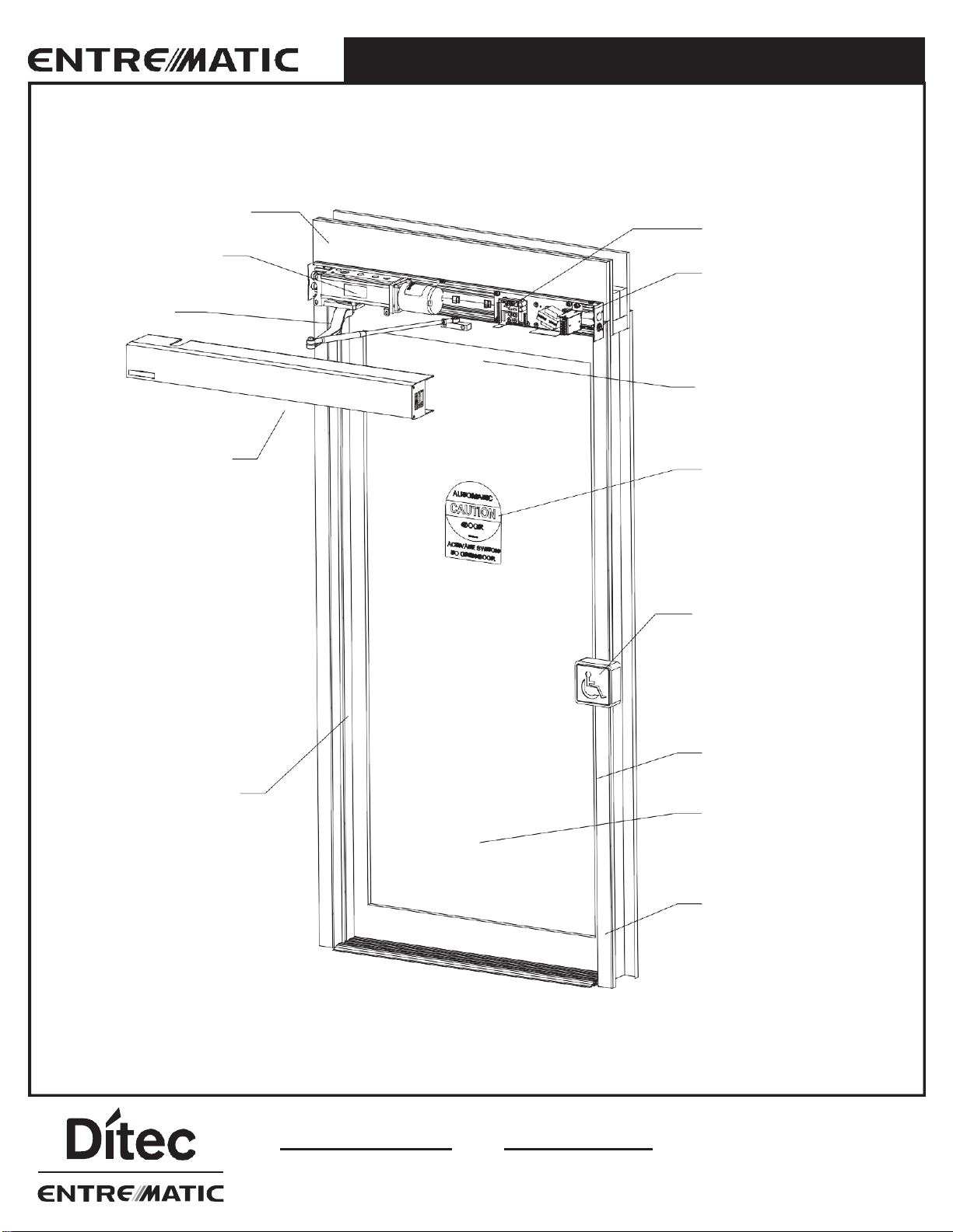
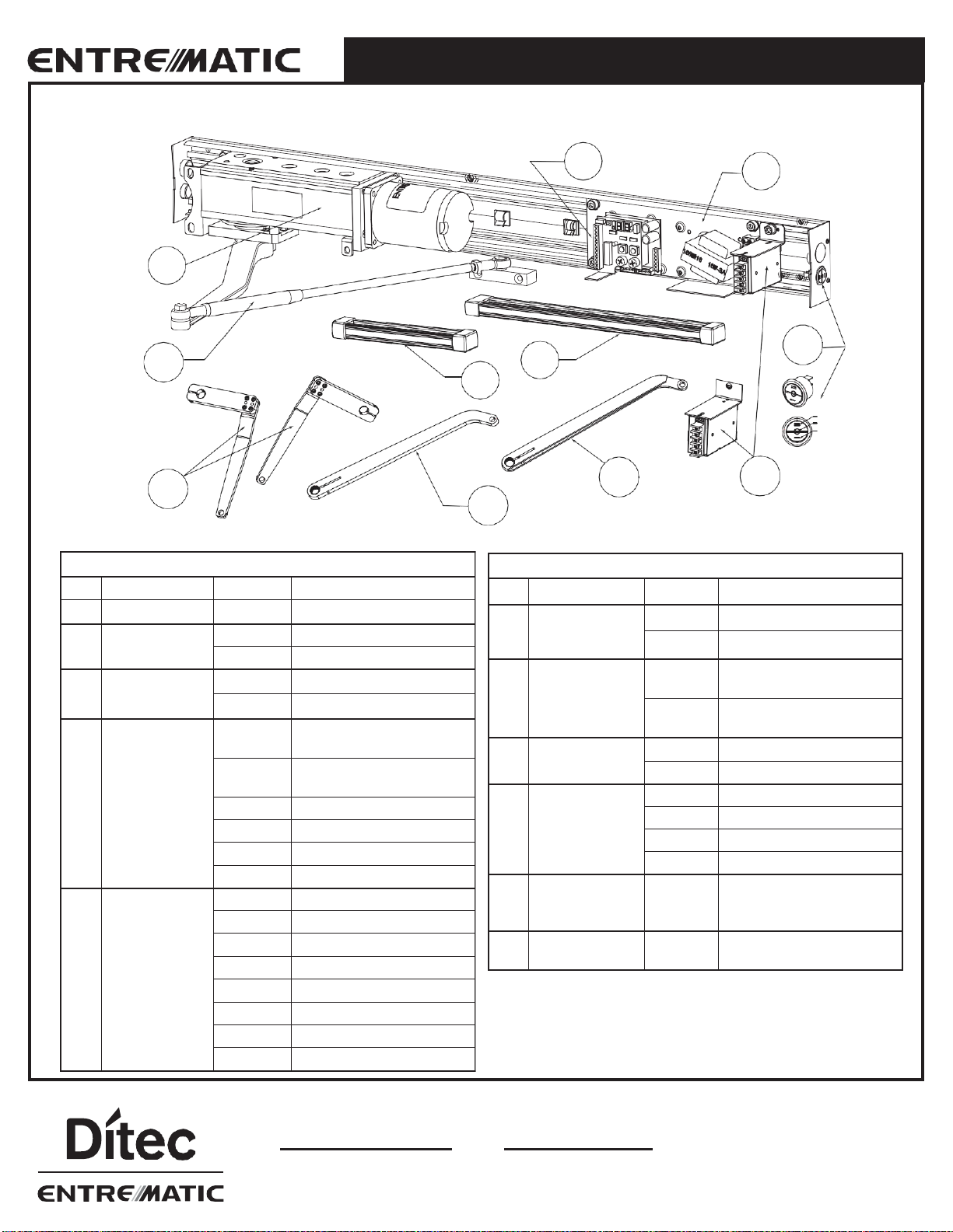
The HA8-LP Operator is a complete swinging door solution for push, pull, surface applied installations. The header contains
the Driving system (Motor), Torque production (Gearbox), and a Control system to interlink the two.
The HA8-LP Operator ensures all-around safety. It can be combined with the full range of safety units, such as presence
and motion sensors. It is easy to install for both new construction and retrofit applications.
•All wiring must conform to standard wiring practice in accordance with national and local wiring codes.
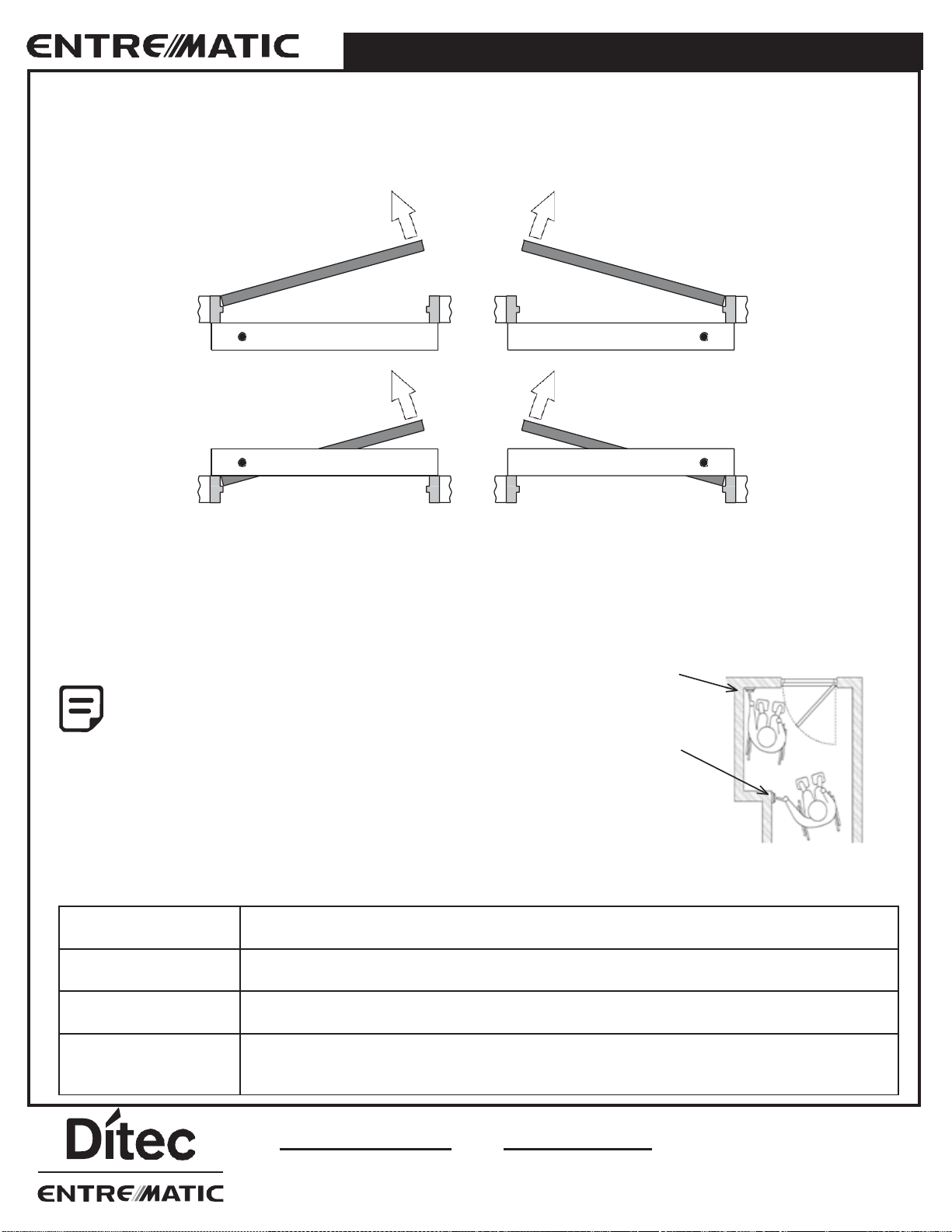
•Door must swing freely through the entire opening and closing cycle before beginning of installation.
Typically, doors are hung on hinges 5” (127mm) maximum width or 3/4” (19mm) offset pivots.
•An incorrectly installed or improperly adjusted door operator can cause property damage or personal injury.
These instructions should be followed to avoid the possibility of misapplication or maladjustment.
•All dimensions are given in inches (millimeters), unless otherwisenoted.
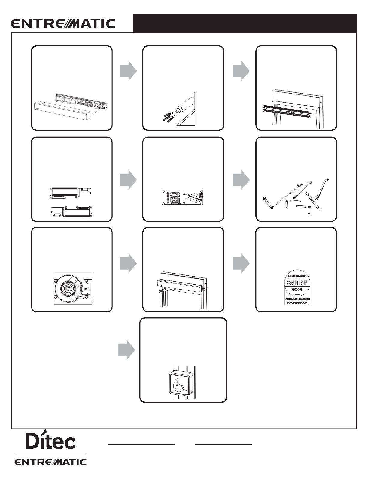
Door/Frame Preparation
•Before installation, verify door frame is properly reinforced and is well anchored in the wall.
•Concealed electrical conduit, and concealed switch or sensor wires should be pulled to the frame before proceeding.
Suggested Fasteners for Frame
•#14 x 2-3/4” (70mm) long sheet metal screws.
Suggested Fasteners for Door
•#12, #14, Wood screws, Sheet Metal screws, Self-tapping screws of varying lengths depending on applications.
The fastener components listed above are merely suggestions. A technician should use their best
discretion to determine what components they’ll need to complete thejob.
Do Not use Drywall Screws or Hollow Wall Anchors to mount the Back Plate / Header.
Shipping inspection
Verify that the order was shipped complete and correct, including model number, door handing, color, and header width.
•If any of the above items are not correct, do not attempt to install until all conditions are correct
•Report any incorrect items to the general contractorimmediately.
NO CLAIMSFOR SHORTAGES WILL BE ALLOWED UNLESSREPORTED
WITHIN 24HOURSOF RECEIPTOFSHIPMENT.
Safety Precautions
•Do not climb or put weight on any door or headerparts
•Do not let children play with the operator or the electricalboard
•Keep remote controls away from children
•Keep all power off to the unit, when performing any work ormaintenance
Toavoid bodily injury, material damage and malfunction of the product, the instructions contained in this manual must be
strictly observed during installation, adjustment, repairs and service etc. Training is needed to carry out these tasks safely.
Only Entrematic-trained technicians should be allowed to carry out theseoperations.
1.0 BEFORE INSTALLATION

Entrematic Canada Inc.
Toll Free: 1-877-348-6837
info.ditec.ca@entrematic.com
www.ditecentrematic.ca
Entrematic USA Inc.
Toll Free: 1-866-901-4284
info.ditec.us@entrematic.com
www.ditecentrematic.us
Pg. 8
HA8-LP Manual V. 5.0
1.0 BEFORE INSTALLATION
Compliance Codes and Standards
The operator complies with the following codes and standards:
•UL STD.325 & ANSI/BHMA STD. A156.19; Fire rated UL STD. 10 (b); UL STD. 10(c); NFPASTD. 252
•CAN/CSA STD. C22.2 NO. 247 & CAN/ULC STD.S104
•Under No Circumstances shall the Certification Label of the HA8 operator be tampered, modified
or removed!
•It is the responsibility of the final installer and/or installation company, to certify that the final
completed operator is installed in accordance with local building codes and applicable laws.
1.3 Technical Specifications & Required Tools
Model
Ditec Entrematic HA8 LP
Dimensions
4.125” W x 5.125”H
Weight
Approx. 45 lbs
Power Supply
115 ± 5VAC, 60Hz, 3A
Consumption
DC16V/ 3 AMP
Motor
1/8 hp, 16VDC, 3A (Standard)
Rated Operation
Continuous opening and closing cycles
Manual Opening/Closing Force
- during power failure
Opening Force: 15 lbs; Closing Force: 25lbs
Door Opening/Closing Speed & Force
Adjustable, see section 10.0 ADA ADJUSTMENTS
Operation - during power failure
Low resistance when opened by hand. Door closes by spring.
Hold Open
Pulsed Energy to Motor. No overheating. Continuous hold open
Operating Environment
Ambient temperature -4F to +120F (-20C to +50C) No condensation or icing
Ambient humidity 30% to 85% RH
(No hazardous materials must be present in the atmosphere)
Required Tools for installation:
•Allen Wrench Set
•Screwdrivers: Flat, Philip, 5/16” Hex.Nut
•Power Drill and Drill Bits
•Additional Fasteners Depending Surface
•Level
•Shims
•Tape Measure
•Hand Saw/ Power Saw
•Wire Stripper

Entrematic Canada Inc.
Toll Free: 1-877-348-6837
info.ditec.ca@entrematic.com
www.ditecentrematic.ca
Entrematic USA Inc.
Toll Free: 1-866-901-4284
info.ditec.us@entrematic.com
www.ditecentrematic.us
Pg. 9
HA8-LP Manual V. 5.0
1.4 Door Handings
1.0 BEFORE INSTALLATION
The handing and types of each operator are shown in the figure below; the black dot indicates the spindle location.
The HA8-LP Operator can be used for pull side and push side installation, on the top door jamb and in header applications.
Left-Push Surface Right-Push Surface
Left-Pull Surface Right-Pull Surface
1.5 Consideration of Surroundings
Floor Space Requirements for Wheel Chair Maneuvering - Americans with Disabilities Act (ADA)
The owner may request the activation device location; however, the press switch must be in view of the door and not directly
on the door or frame. Please refer to ANSI 117.1 Safety Code for further guidelines on switch requirements.
Position# 1
Minimum Two Feet (2’)
Activation switches shall be at minimum height of
36” and maximum height of 48” from finished floors
or as specified by a local Authority Having
Jurisdiction.
Individual who uses wheelchair needs a minimum
of 48”clearance to the door swing for doors
in sequence application.
from door latch
Position# 2
Minimum Five Feet (5’)
from door face
External and Internal Factors
Door Condition
Door must move easily open and close (latch) without excessive force; weather stripping and
threshold must not interfere with door movement.
Reveal
For out swing (Push) doors, the reveal must be within the range of 0” to 14”. For in swing (Pull)
doors, 0” to 4” for special reveals is allowed –for all others consult factory.
Wind
When installing on a door in a strong wind condition area, special adjustments should be made
to the arm and doorstop position, to increase the spring tension.
Power/Control Wires
Check that the electrical feed, all conduits, and electrical junction boxes (for push plates or
other activation devices, if required) are correctly located in accordance with final approved
shop drawings and within the guidelines of the enforced local electrical codes.

Entrematic Canada Inc.
Toll Free: 1-877-348-6837
info.ditec.ca@entrematic.com
www.ditecentrematic.ca
Entrematic USA Inc.
Toll Free: 1-866-901-4284
info.ditec.us@entrematic.com
www.ditecentrematic.us
Pg. 10
HA8-LP Manual V. 5.0
1.6 Electrical
The 115±5VAC supply lines are connected to the black primary wires coming from the transformer and the ground wire
is attached to the operator header box. Mount the ON/OFF/HOLD OPEN switch in the header end plates to the latch side of
the unit (or closest to the controlboard).
The control board settings have been pre-set prior to shipment. It will be necessary for the door operator to be functional
while adjustments and settings are made. A black push actuator is mounted on the upper left corner of the circuit board to
ease in the adjustment process. Power up the unit, push an activating device and check to make sure that the spline pinion
drive rotates in the correct direction. Keep all wires away from moving parts and sharp edges that may cut into the outer
casing of the wires.
Installation of L-16 CONNECTOR
for armor (Bx) cable/ incoming
power (to secure line to header)
IS RECOMMENDED
THE GROUND WIRE FOR THE INCOMING 115 ±5VAC POWER AND THE SYSTEM GROUND WIRE
CANNOT SHARE THE SAME GROUNDING STUD. GROUND THE INCOMING 115±5VAC ACCORDINGLY.
•Installation of any extra wiring for controls or accessories into the header unit shall be secured and away
from any moving parts.
•If the motor is not plugged into the circuit board, there is no resistance against the spring when manually
opening the door. The door or arm will close very quickly if opened.
•If an electrical access hole is added or knocked-out of the end plates, code approved electrical transfers
must be used. Hole cannot be knocked out and unfilled.
1.0 BEFORE INSTALLATION

Entrematic Canada Inc.
Toll Free: 1-877-348-6837
info.ditec.ca@entrematic.com
www.ditecentrematic.ca
Entrematic USA Inc.
Toll Free: 1-866-901-4284
info.ditec.us@entrematic.com
www.ditecentrematic.us
Pg. 11
HA8-LP Manual V. 5.0
2.1 Pre-Mounting Header Box Instructions
Disassemble parts for installation
Remove the cover from the assembly by gently prying with a screwdriver. Once the snaps are clear, pull the cover outwards
with minimal effort. Carefully set the cover in a location where it will not be damaged.
Power supply may be pulled into the header at the same time the header assembly is positioned. Make sure all power is
turned off before handling the supply wires. This should be done by a certified electrician and within the guidelines of the
enforced local electrical codes.
Be sure there is proper support in the wall to secure the header at the vertical jambs, and behind the header at intervals
between the vertical jambs. Secure the header box to the top of the door frame with the appropriate fasteners as indicated
below.
Remove the motor/gearbox and control board from the back plate. Make through holes on the back plate for mounting
header where appropriate.
2.0 OPERATOR INSTALLATION

Entrematic Canada Inc.
Toll Free: 1-877-348-6837
info.ditec.ca@entrematic.com
www.ditecentrematic.ca
Entrematic USA Inc.
Toll Free: 1-866-901-4284
info.ditec.us@entrematic.com
www.ditecentrematic.us
Pg. 12
HA8-LP Manual V. 5.0
STEPS
1Verify that the operator is the correct orientation. Left Push, Right Push, Left Pull or Right Pull
2Holes are provided for the high voltage wires. Hold the back plate in position and mark the wall. If the hole is not at a
convenient location, you can drill the backer plate tosuit.
3Anchor the back plate to the wall with minimum of six (6) - #14 x 1” Pan Quad TypeAscrews (provided). You may need
to provide other screws if your installation requires it.
4Use two (2) screws to fasten the back plate directly to the doors vertical jambs on the hinge side.
Holes can be made anywhere in header to secure. All holes MUST be drilled into substantial
support (studs, blocks, framing, etc.). This diagram may not reflect your installation.
Do Not use Drywall Screws or Hollow Wall Anchors to mount the Back Plate / Header.
TYPICAL THROUGH-HOLE INSTALLATION
PRE-DRILLED UPPER HEADER ANCHORING HOLES
PRE-DRILLED INCOMING POWER WIRE HOLE
(TYPICALLY LATCH SIDE)
DOOR FRAME HEADER
ANCHORING HOLES
2.0 OPERATOR INSTALLATION

Entrematic Canada Inc.
Toll Free: 1-877-348-6837
info.ditec.ca@entrematic.com
www.ditecentrematic.ca
Entrematic USA Inc.
Toll Free: 1-866-901-4284
info.ditec.us@entrematic.com
www.ditecentrematic.us
Pg. 13
HA8-LP Manual V. 5.0
VERTICAL SECTION
FILLER PLATE
AS REQUIRED,
BY OTHERS
REINFORCEMENT
BY OTHERS
5 1/8 in
[130mm]
HA8-LP
OPERATOR
& HEADER
3 7/8 in
[98mm]
FLUSH
5Add additional screws to fasten the header back plate to the door frame approximately 12” to 16” apart.
The header must support 200 lbs.
6When installing a support plate for the full width of the door frame, fasten an additional two (2) screws to the vertical
jambs on the strike side of thedoor.
7Install the Spindle into the motor/gearbox.
8•Once the header back plate is in place, install the motor/gearbox and control board to the header back plate
(see Section 3.0).
•Slide the nuts (supplied with the operator) to hold the motor/gear box and control board along the 2 parallel tracks
on the back plate.
•Fasten the bolt to hold the motor/gear box and control board. The motor/gearbox needs to be installed so that the
center of the spindle is 5” (127mm) from the endplate
2.0 OPERATOR INSTALLATION
4 1/8 in
[102mm]

Entrematic Canada Inc.
Toll Free: 1-877-348-6837
info.ditec.ca@entrematic.com
www.ditecentrematic.ca
Entrematic USA Inc.
Toll Free: 1-866-901-4284
info.ditec.us@entrematic.com
www.ditecentrematic.us
Pg. 14
HA8-LP Manual V. 5.0
2.2 Operator Layout and Handing
HORIZONTAL SECTION
PUSH HEADER PULL HEADER
SWING SIDE
HINGE PIVOT
APPROACH SIDE
APPROACH SIDE
HINGE PIVOT
HEADER LENGTH DOOR WIDTH
+ 3” [ 76.2mm ]
SWING SIDE
VERTICAL SECTION
PUSH HEADER PULL HEADER
FILLER
FLUSH
FILLER
1 3/8in 35mm
For Universal Arm application, please see section 3.3
2.0 OPERATOR INSTALLATION
HEADER LENGTH DOOR WIDTH
+ 3 in [ 76mm ]
HEADER LENGTH DOOR WIDTH
+ 3 in [ 76mm ]
Door Swings Out
Approach Side
Swing Side
Door Swings Out
Swing Side
Approach Side
Hinge Pivot
Hinge Pivot

Entrematic Canada Inc.
Toll Free: 1-877-348-6837
info.ditec.ca@entrematic.com
www.ditecentrematic.ca
Entrematic USA Inc.
Toll Free: 1-866-901-4284
info.ditec.us@entrematic.com
www.ditecentrematic.us
Pg. 15
HA8-LP Manual V. 5.0
Push Header
The Header Box on push installations is mounted flush to the bottom of the doorjamb header. It may require solid backing
material to compensate for the thickness of the door frame. Before fastening header box to the door frame, ensure that
your access holes for high and low voltage wires match. Header box should be mounted to the hinge side of the door.
For most applications, the header is equal to door opening plus 3”. This allows for a 1½” space on either side of the
Header Box to anchor the header box properly to the frame. The header box should be anchored with a minimum of
(6) Six, #14 x 1” Pan Quad Type A screws (provided.)
•The locations of the screws on the header will be applicationdependent.
•Fasten the header body as application requires. The header must support 200lbs.
•Do Not use Drywall Screws or Hollow Wall Anchors to mount the Back Plate / Header.
•Header MUST be installed 1.5 inches from hinge side for all Push/ Pull installation, regardless of
whether header is sized appropriately to dooropening.
•For Push application with standard arm, the reveal is up to 14”. For greater reveal, extended arm
is needed.
HEADER LENGTH = DOOR OPENING WIDTH + 3in [76mm]
1.50in 38mm IMPORTANT
1.50in 38mm
HINGE
STILE
DEPENDING ON OPTION
~2in or ~3in [~51mm or ~76mm]
PUSH ARM DOOR SHOE
14in
356mm
DOOR OPENING WIDTH
STRIKE
SIDE
2.89in [74mm] DISTANCE BETWEEN HEADER END CAP
AND BOTTOM GEARBOX BRACKET (SEE SECTION 2.5)
2.0 OPERATOR INSTALLATION

Entrematic Canada Inc.
Toll Free: 1-877-348-6837
info.ditec.ca@entrematic.com
www.ditecentrematic.ca
Entrematic USA Inc.
Toll Free: 1-866-901-4284
info.ditec.us@entrematic.com
www.ditecentrematic.us
Pg. 16
HA8-LP Manual V. 5.0
Pull Header
Ensure before fastening Header box to the door frame that your holes for high and low voltage wires match. Header box
should be referenced to the hinge side of the door and 1 3/8” above the bottom of the door frame (see figure below).
For most applications, the header is equal to the door opening plus 3”.
This allows for a 1.5” space on either side of the Header Box to anchor the Header box properly to the frame.
For correct sized header, the header box should be anchored with a minimum of (6) six #14 x 1” Pan Quad Type A screws
(provided), but will also depends on what is being screwed into.
•The locations of the screws on the header will be application dependent.
•Fasten the header body as application requires. The header must
support 200lbs.
•Do Not use Drywall Screws or Hollow Wall Anchors to mount the
back plate / header.
•Header on pull applications must be mounted so the main drive
pinion safety washer and machine screw are above the top of the
door. This is to ensure the spindle does not obstruct the swing path
of thedoor.
•For application with Universal arm, header will be installed differently.
See section3.4.
2.3 Handing Modification - Left to Right (and vice versa)
Prepare the Operator, Arm and Spindle
1Invert the entire operator assembly 180degrees
2Remove drive shaft (spindle) from motor gear box assembly (See changing position of drive shaft)
3Re-attach drive shaft (spindle) to opposite side of motor gearboxassembly
4Detach wire connections from operator to controlboard
5Remove control assembly from the base and rotate 180degrees
6Replace control and socket screws
7Connect wire harness (see wiring)
8Fully tighten all bolts
9Insert spline shaft on the operator (depended on push or pull application and spindle rotation)
2.0 OPERATOR INSTALLATION
1 3/8in [34.23mm]
Filler

Entrematic Canada Inc.
Toll Free: 1-877-348-6837
info.ditec.ca@entrematic.com
www.ditecentrematic.ca
Entrematic USA Inc.
Toll Free: 1-866-901-4284
info.ditec.us@entrematic.com
www.ditecentrematic.us
Pg. 17
HA8-LP Manual V. 5.0
Operator placement
LEFT HAND PUSH
(”SPINDLE OPENING ROTATION” LABEL FACING DOWN)
HINGE
SIDE
RIGHT HAND PUSH
(”SPINDLE OPENING ROTATION” LABEL FACING UP)
HINGE
SIDE
Before you begin, note that direction of the Open/Back Check arrow will indicate the direction the unit will open when
activated.As mentioned earlier, if the operator label is facing down to the floor, then the handing is Left hand Push/Pull.
If the operator label is facing up to the ceiling, the handing is Right hand Push/Pull.
1Remove gear box assembly from mounting plate.
2Disconnect wire harnesses and switch wiring from control (seewiring).
3Re-attach gear box to opposite side of mounting plate and rotate mounting plate. The arrow should be pointing upward.
This indicates the handling is Left Hand Pull.
4Connect wire harness and switch wiring (seewiring).
5Fully tighten allbolts.
2.0 OPERATOR INSTALLATION
Spindle Opening
Rotation Label
Handing Modification Steps
LEFT HAND PULL
(“SPINDLE OPENING ROTATION” LABEL FACING DOWN)
RIGHT HAND PULL
(“SPINDLE OPENING ROTATION” LABEL FACING UP)
HINGE
HINGE

Entrematic Canada Inc.
Toll Free: 1-877-348-6837
info.ditec.ca@entrematic.com
www.ditecentrematic.ca
Entrematic USA Inc.
Toll Free: 1-866-901-4284
info.ditec.us@entrematic.com
www.ditecentrematic.us
Pg. 18
HA8-LP Manual V. 5.0
2.4 Double Egress Header
Double Egress Operators have a PULL type and PUSH type operator in the same housing, the header must be mounted
1 3/8” above the door frame. For PUSH type operator, arm clearance issues may arise. Toensure the arm clears any
existing doorstops, mount the arm according to the diagram below marked Push Configuration.
See Section 3.1 to change the Push arm configuration.
LENGTH ‘L’ = DOOR WIDTH + 3”
2.0 OPERATOR INSTALLATION
[ 76mm ]
[ 140mm ]
5 ½”

Entrematic Canada Inc.
Toll Free: 1-877-348-6837
info.ditec.ca@entrematic.com
www.ditecentrematic.ca
Entrematic USA Inc.
Toll Free: 1-866-901-4284
info.ditec.us@entrematic.com
www.ditecentrematic.us
Pg. 19
HA8-LP Manual V. 5.0
2.5 Control board and Gearbox Installation
The control board will be on the opposite side of the gearbox motor. For example, in a Left Hand Push operator, the
control board is right of the gearbox motor (as diagram below).
Control board and power supply kit can
be repositioned by loosen the screws.
LP GEARBOX MOUNTING DISTANCE
2.89in 73.41mm
DISTANCE BETWEEN HEADER END CAP
AND BOTTOM GEARBOX BRACKET
2.0 OPERATOR INSTALLATION

Entrematic Canada Inc.
Toll Free: 1-877-348-6837
info.ditec.ca@entrematic.com
www.ditecentrematic.ca
Entrematic USA Inc.
Toll Free: 1-866-901-4284
info.ditec.us@entrematic.com
www.ditecentrematic.us
Pg. 20
HA8-LP Manual V. 5.0
LP GEARBOX INSTALLATION/REMOVAL
LH PUSH/ PULL GEARBOX ORIENTATION
(”SPINDLE OPENING ROTATION” LABEL FACING DOWN)
TO MOUNT/REMOUNT GEARBOX,
REMOVE THESE SCREWS & WASHERS IN
NUMERICAL ORDER.
RH PUSH/ PULL GEARBOX ORIENTATION
(”SPINDLE OPENING ROTATION” LABEL FACING UP)
LP GEARBOX FASTENER DETAILS
ALL COMPONENTS ANCHORED TO
HEADER VIA M8 X 1 OR 5/16”-18
HEX NUT IN CHANNELS
M8X1 OR 5/16”-18 X 1/2”
SOCKET CAP SCREW HOLDS ALL
OTHER COMPONENTS TO HEADER
WITH ONE (1) 5/16” LOCK WASHER
M8X1 OR 5/16”-18 X 5/8”
SOCKET CAP SCREW HOLDS
GEARBOX TO HEADER (1, 2 & 3).
MUST HAVE TWO (2) 5/16”
LOCK WASHER BEFORE
BRACKETS OF GEARBOX.
2.0 OPERATOR INSTALLATION
This manual suits for next models
1
Table of contents
Other DITEC Door Opening System manuals

DITEC
DITEC OLLY M Manual

DITEC
DITEC GT Series Manual

DITEC
DITEC PAS024AMT User manual

DITEC
DITEC VALOR HH-HS User manual

DITEC
DITEC Entrematic ENERGY 49E User guide

DITEC
DITEC DAS200T User manual

DITEC
DITEC OLLY C Manual

DITEC
DITEC DAB105 User manual

DITEC
DITEC DAB305 User manual

DITEC
DITEC DAS107 User manual
Popular Door Opening System manuals by other brands

Dormakaba
Dormakaba TS9356 PKT 120/170 installation instructions

Assa Abloy
Assa Abloy Adams Rite EX89 Preparation guide

Chamberlain
Chamberlain K1A6636 quick start guide

Assa Abloy
Assa Abloy Besam SW300 Installation and service manual

Assa Abloy
Assa Abloy Corbin Russwin PED5600 Series installation instructions

Eco
Eco TS-31 Assembly instruction