manuals.online logo
Brands
  1. Home
  2. •
  3. Brands
  4. •
  5. Dormakaba
  6. •
  7. Lock
  8. •
  9. Dormakaba SafeRoute-System Mini User manual

Dormakaba SafeRoute-System Mini User manual

EN
WN 059721 45532 – 2019-01
User manual
SafeRoute®-System
Mini, Basic and Standard
Contents
1 About this document 2
1.1 Contents and purpose 2
1.2 Target group 2
1.3 Documents storage 2
1.4 Symbols used 2
2 Safety 2
2.1 Intended use 2
2.2 Obligations of the facility operator 2
2.3 Obligations of the user 2
3 Product description 2
4 Operation 3
4.1 Deactivate the electric locking device in an
emergency 3
4.2 Briefly unlock the electric locking device 3
4.3 Unlock the electric locking device long-term
(from Standard license) 3
4.4 Permanently unlock the electric locking device 3
4.5 Reactivate the electric locking device after
unlocking 3
4.6 Turn off the alarm signal 3
5 Maintenance 3
6 Manufacturer's declarations and test
certificates 3
7 Status display 4
3 Product description
A SafeRoute® system is an electrical locking and
monitoring system for doors along emergency and
escape routes and ensures that people can escape
unhindered in the event of danger.
Emergency exit door in normal operation:
The electric locking device is active. The locking
device can be deactivated via the key switch. The
status of the electric locking device is indicated by
the integrated illuminated ring, e.g. if it hasn’t locked
successfully (“door open” monitoring). In addition, an
audible alarm signal can sound.
Emergency exit door in the event of alarm/danger:
The electric locking device is deactivated by pressing
the emergency button. At the same time, an audible
and visual alarm is triggered.
1
2
Fig. 1 Triggering and operating elements of a SafeRoute®
system
Element Function
Emergency
button (1)
• In normal operation:
Door unit’s status display
• In the event of alarm/danger:
-deactivate electric locking device
(triggers alarm)
- alarm is signaled visually.
Key switch
(2)
• In normal operation:
deactivate electric locking device
(does not trigger an alarm) and
reactivate
• After alarm trigger:
reactivate the electric locking
device
1 About this document
1.1 Contents and purpose
This document explains the operation of the
SafeRoute® escape route security system.
1.2 Target group
This manual is intended for the facility operator and
user of the emergency exit door.
1.3 Documents storage
This manual is to be kept for the entire service life.
1.4 Symbols used
Safety instructions are marked with symbols. The
safety instructions are introduced by signal words
that express the extent of the hazard, e. g.:
WARNING
This signal word indicates a situation of
potential risk, which could lead to death or
serious injury if not averted.
2 Safety
2.1 Intended use
A SafeRoute® system is an electrical locking system
for doors along emergency and escape routes and
ensures that people can escape unhindered in the
event of danger. SafeRoute® prevents the escape
route from being misused. The intended use includes
compliance with all information in this manual.
2.2 Obligations of the facility operator
Proper operation of the SafeRoute® escape route
security system must be ensured. The users should
be familiarized with the unit and the triggering
and operating elements. Furthermore, it must be
ensured that the maintenance intervals are observed.
Maintenance must be arranged at least once a year in
accordance with the inspection log.
2.3 Obligations of the user
Unit malfunctions must be reported to the facility
operator immediately.
2SafeRoute®-System 2019-01
WN 059721 45532
dormakaba Operation manual About this document
4 Operation
4.1 Deactivate the electric locking device
in an emergency
1. Press the emergency button.
‣ An alarm signal sounds.
→The electric locking device is deactivated.
4.2 Briefly unlock the electric locking device
1. Insert the key into the profile cylinder.
2. Push the key to the right and hold for 1-7 s
(default value < 8 seconds).
‣ The electric locking device is deactivated.
→The unlocking time of 5 s (default value) runs
out. Thereafter, the door locks automatically
(door must be closed).
4.3 Unlock the electric locking device long-
term (from Standard license)
1. Insert the key into the profile cylinder.
2. Push the key to the right and hold for 8-14 s
(default value 8 s).
‣ The electric locking device is deactivated.
→The unlocking time of 5 min (default
value) runs out. Thereafter, the door locks
automatically (door must be closed).
4.4 Permanently unlock the electric locking
device
1. Insert the key into the profile cylinder.
2. Push the key to the right and hold for at least 15s
(default value).
→The electric locking device is deactivated
permanently.
4.5 Reactivate the electric locking device
after unlocking
1. Close the door.
2. Push the key to the left.
→The electric locking device is activated.
4.6 Turn off the alarm signal
1. Close the door.
‣ The electric locking device is active.
→The alarm signal is turned off.
If the alarm signal continues:
1. Push the key switch to the right and bring it back
to the middle position.
‣ The alarm signal is acknowledged.
If the alarm signal continues:
1. Push and hold the key to the right on the flashing
emergency button’s key switch.
2. Press the emergency button for 1s and then
release.
3. Push the key over the middle to the left and bring
it back to the middle position.
4. Remove the key.
‣ The electric locking device is active.
→The alarm signal is turned off.
5 Maintenance
The facility operator commissions the maintenance.
Maintenance is periodic and is performed by service
technicians authorized by dormakaba.
Customer service
dormakaba Service can be reached at the toll-free
number.
E-mail: [email protected]om
Fax: +49 2333 793-3777
dormakaba
SERVICE
24 h HOTLINE
0800 - 5240246
Other contact options:
• dormakaba - Technical Competence Center
Tel.: +49 2333 7932900
• Online repair order: www.dormakaba.com
dormakaba Service App for smartphone/tablet: Apple
iOS Appstore or Google Android Playstore
6 Manufacturer's declarations
and test certificates
Any required documents, such as e.g. the EC
Declaration of Conformity, the manufacturer's
Declaration of Conformity, and compatibility lists, are
available at www.dormakaba.com.
3SafeRoute®-System 2019-01WN 059721 45532
dormakaba Operation manual Operation
dormakaba Deutschland GmbH
DORMA Platz 1 58256 Ennepetal Germany T: +49 2333 793-0 F: +49 2333 793-4950 www.dormakaba.com
7 Status display
The door unit’s status display is indicated via the
illuminated ring on the emergency button. The LED
segments light up or blink in color depending on the
door status. In the event of an alarm, an signal sounds
as well.
WARNING
The service technician must be called
immediately in the event of a permanent
alarm or an unidentifiable display on the
illuminated ring.
Table of displays on the emergency button’s
illuminated ring
LED display Door status Recommended procedure
1. LED display in normal operation
The electric
door locking device is
activated.
–
A B C
The electric door locking
device is
A. briefly unlocked
B. unlocked long-term* or
C. permanently unlocked
–
2. LED display in case of alarm
“Door open” alarm
(one yellow LED per locking
device, here: 4 connected
locks)
Turn off the alarm signal (see Ch. 4.6)
Emergency button pressed Turn off the alarm signal (see Ch. 4.6)
Alarm system triggered After resetting the fire detector or smoke
switch, this alarm trigger is automatically
reset.
or
Tamper alarm
red-yellow = locked door
green-yellow = unlocked door
Check all the connected devices’ housings
for correct screw connection and seal them
correctly if necessary. Turn off the alarm
signal (see Ch. 4.6). If the alarm continues,
call the service technician.
3. LED display in case of malfunction or maintenance
(no display)
Power supply is missing
or emergency button is
defective
Turn on the power.
If the LED display does not change, call the
service technician.
or
Maintenance required
• red-yellow = locked door
• green-yellow = unlocked
door
Inform the facility operator and/or call the
service technician.
*Long-term unlocking from Standard license
Translation of the original document, subject to change without notice

This manual suits for next models

2

Other Dormakaba Lock manuals

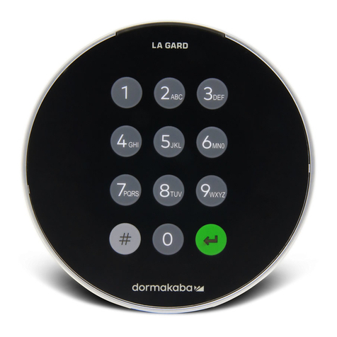
Dormakaba AUDITCON 2 SERIES User manual
Dormakaba

Dormakaba AUDITCON 2 SERIES User manual

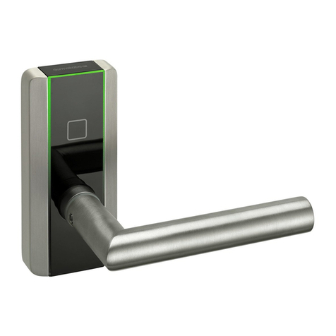
Dormakaba LA GARD 700 Series User manual
Dormakaba

Dormakaba LA GARD 700 Series User manual

Dormakaba 2725-K6 User manual

Dormakaba

Dormakaba 2725-K6 User manual

Dormakaba SVI 5000 Training manual

Dormakaba

Dormakaba SVI 5000 Training manual
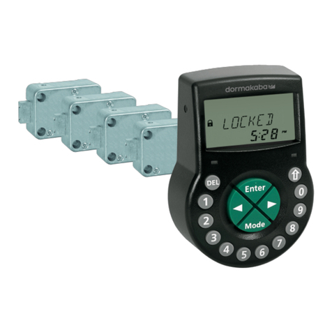
Dormakaba Axessor CIT User manual

Dormakaba

Dormakaba Axessor CIT User manual
Dormakaba RCI DE8310 V1.6 User manual

Dormakaba

Dormakaba RCI DE8310 V1.6 User manual
Dormakaba T900 User manual

Dormakaba

Dormakaba T900 User manual
Dormakaba Classic User manual

Dormakaba

Dormakaba Classic User manual
Dormakaba SVI Series User manual

Dormakaba

Dormakaba SVI Series User manual

Dormakaba LA GARD 700 Series User manual

Dormakaba

Dormakaba LA GARD 700 Series User manual

Dormakaba YD30D Manual

Dormakaba

Dormakaba YD30D Manual

Dormakaba LA GARD 700 Series User manual

Dormakaba

Dormakaba LA GARD 700 Series User manual

Dormakaba UNIVERSAL Light US 10 User manual

Dormakaba

Dormakaba UNIVERSAL Light US 10 User manual

Dormakaba Cobalt Single User manual

Dormakaba

Dormakaba Cobalt Single User manual
Dormakaba Axessor Series User manual

Dormakaba

Dormakaba Axessor Series User manual
Dormakaba LA GARD ComboGard Pro 39E Manual
Dormakaba

Dormakaba LA GARD ComboGard Pro 39E Manual

Dormakaba GL220 User manual

Dormakaba

Dormakaba GL220 User manual
Dormakaba ORACODE 660i User manual

Dormakaba

Dormakaba ORACODE 660i User manual
Dormakaba M Series User manual

Dormakaba

Dormakaba M Series User manual
Dormakaba RCI 3513-DM User manual

Dormakaba

Dormakaba RCI 3513-DM User manual

Dormakaba STV 2 Series User manual

Dormakaba

Dormakaba STV 2 Series User manual

Dormakaba UNIQUIN User manual

Dormakaba

Dormakaba UNIQUIN User manual

Dormakaba 8H Series User manual

Dormakaba

Dormakaba 8H Series User manual

Dormakaba SVA 6000 Training manual

Dormakaba

Dormakaba SVA 6000 Training manual

Popular Lock manuals by other brands

Assa Abloy hes 8000 Series installation instructions

Assa Abloy

Assa Abloy hes 8000 Series installation instructions

Abus CodeLoxx user manual

Abus

Abus CodeLoxx user manual

IFAM R4MK instructions

IFAM

IFAM R4MK instructions

Falcon MA Series Service manual

Falcon

Falcon MA Series Service manual

COMPX SW20-3118MC Dimensional drawing

COMPX

COMPX SW20-3118MC Dimensional drawing

Assa Abloy effeff EX118R installation instructions

Assa Abloy

Assa Abloy effeff EX118R installation instructions

LEHMANN DIAL LOCK 59 operating instructions

LEHMANN

LEHMANN DIAL LOCK 59 operating instructions

CDVI V3E35R quick start guide

CDVI

CDVI V3E35R quick start guide

Yale YDG313 user guide

Yale

Yale YDG313 user guide

CISA 1-13100-65-0 installation manual

CISA

CISA 1-13100-65-0 installation manual

schmersal AZM300Z-I2-ST-1P2P-N-DU Operation and assembly instructions

schmersal

schmersal AZM300Z-I2-ST-1P2P-N-DU Operation and assembly instructions

DatoHome L-B200 user manual

DatoHome

DatoHome L-B200 user manual

Sargent 7800 installation instructions
Sargent

Sargent 7800 installation instructions

Wano VGLock vG-BL7 user manual

Wano

Wano VGLock vG-BL7 user manual

National Cabinet Lock C8703 Dimensional drawing
National Cabinet Lock

National Cabinet Lock C8703 Dimensional drawing

Vescent D2-135 Quick setup instructions

Vescent

Vescent D2-135 Quick setup instructions

PLS PLS-ML1200 Installer's reference guide
PLS

PLS PLS-ML1200 Installer's reference guide

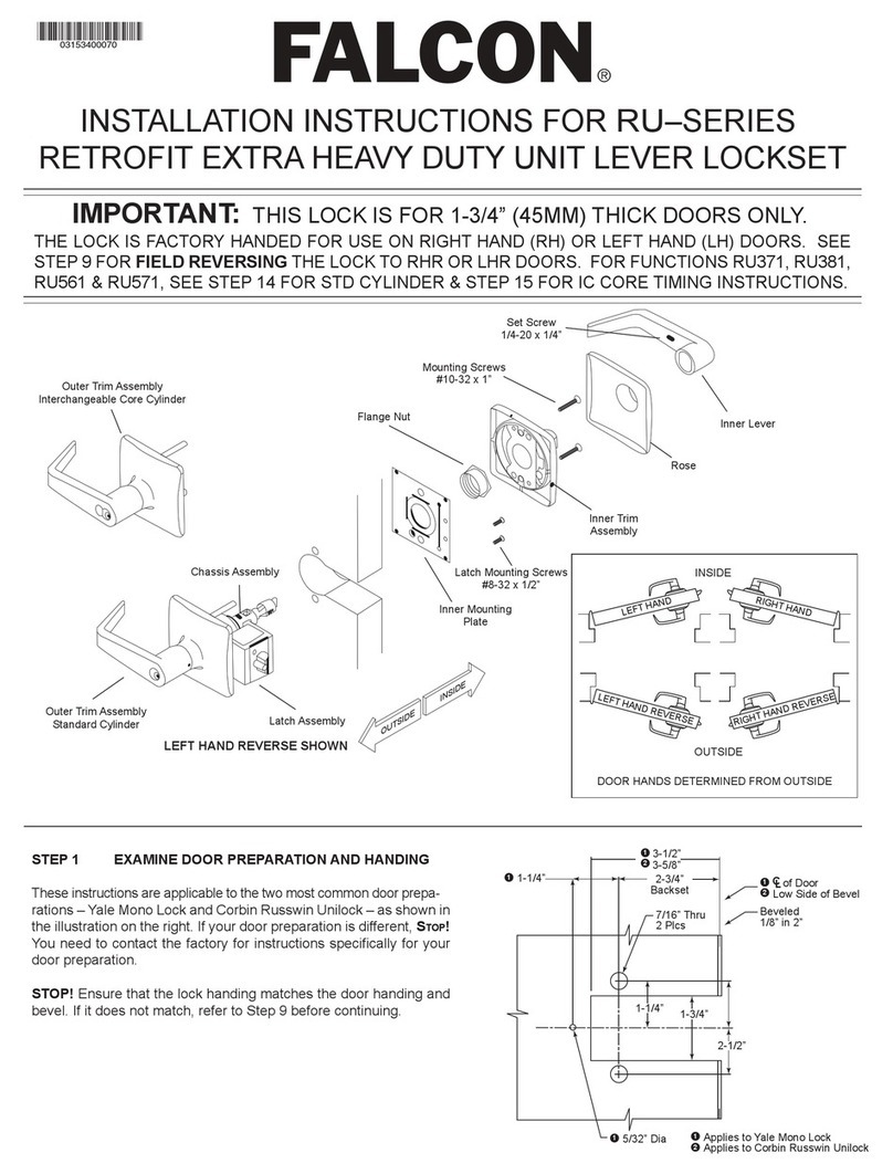
Ingersoll-Rand Falcon RU Series installation instructions

Ingersoll-Rand

Ingersoll-Rand Falcon RU Series installation instructions

manuals.online logo
manuals.online logoBrands
  • About & Mission
  • Contact us
  • Privacy Policy
  • Terms and Conditions

Copyright 2025 Manuals.Online. All Rights Reserved.