manuals.online logo
Brands
  1. Home
  2. •
  3. Brands
  4. •
  5. Dräger
  6. •
  7. Safety Equipment
  8. •
  9. Dräger PAS Micro Series User manual

Dräger PAS Micro Series User manual

PAS®is a registered trademark of Dräger 3352432 (A3-D-P) 1 / 2
3352432
© Dräger Safety UK Limited
Edition 06 – August 2018
Subject to alteration
Draeger Safety UK Limited
Ullswater Close Tel +44 1670 352 891
Blyth, NE24 4RG Fax +44 1670 356 266
United Kingdom www.draeger.com
PAS®Micro Series
Escape repiratory protection equipment Instructions for use
i
1 For your safety
1.1 General safety statements
●Before using this product, carefully read the Instructions for Use.
●Strictly follow the Instructions for Use. The user must fully understand
and strictly observe the instructions. Use the product only for the
purposes specified in the Intended Use section of this document.
●Do not dispose of the Instructions for Use. Ensure that they are
retained and appropriately used by the product user.
●Only fully trained and competent users are permitted to use this
product.
●Comply with all local and national rules and regulations associated
with this product.
●Only trained and competent personnel are permitted to inspect, repair
and service the product. Dräger recommend a Dräger service contract
for all maintenance activities and that all repairs are carried out by
Dräger.
●Properly trained service personnel must inspect and service this
product as detailed in the Maintenance section of this document.
●Use only genuine Dräger spare parts and accessories, or the proper
functioning of the product may be impaired.
●Do not use a faulty or incomplete product, and do not modify the
product.
●Notify Dräger in the event of any component fault or failure.
●The air supply shall meet the requirements for breathing air according
to EN 12021.
1.2 Definitions of alert icons
Alert icons are used in this document to provide and highlight text that
requires a greater awareness by the user. A definition of the meaning of
each icon is as follows:
WARNING
Indicates a potentially hazardous situation which, if not avoided,
could result in death or serious injury.
CAUTION
Indicates a potentially hazardous situation which, if not avoided,
could result in physical injury or damage to the product or
environment. It may also be used to alert against unsafe practices.
NOTICE
Indicates additional information on how to use the product.
2 Description
2.1 Product overview
This variant of the Dräger PAS Micro Series provides respiratory protection
for escaping from a contaminated environment using breathing air from the
air cylinder.
The equipment is available as a 10 minute, 15 minute or 20 minute
version. These are the nominal escape durations, which are determined by
the capacity (volume and pressure rating) of the air cylinder selected. The
actual escape duration is also dependent on the rate at which the wearer
uses air from the cylinder (the breathing rate).
The features of the equipment are:
●The carrying system has a shoulder harness, a waist belt and a
cylinder strap on the rear.
●The pressure reducer (Fig 1, Item 2) connects directly on to the air
cylinder, and reduces the cylinder pressure to the medium pressure
required at the lung demand valve (Fig 1, Item 1).
●The Dräger air cylinder and lung demand valve are described below.
2.1.1 Air cylinder
Cylinders are available with a 200 bar or 300 bar working pressure rating,
and in steel or composite materials. The pressure in the air cylinder is
shown on a contents indicator on the cylinder. Only air cylinders listed in
the Dräger certification are approved for use with the PAS Micro. Contact
Dräger for further information.
2.1.2 Lung demand valve (LDV)
A variety of Dräger lung demand valves are compatible with this
equipment, with the coupling (Fig 2, Item 1) selected to match the face
mask coupling (see table below):
During use, the lung demand valve activates automatically as the wearer
breathes, and then regulates the breathing air supply into the face mask in
response to the breathing rate of the wearer.
●On positive-pressure systems, when the lung demand valve is
activated, the internal valve remains open until closed by the user.
Positive-pressure valves have a reset button (Fig 2, Item 2) that closes
the valve when required. Pressing the reset button closes the internal
valve to switch off the air flow through the lung demand valve.
●On negative-pressure systems the internal valve closes automatically
to switch off the air flow through the lung demand valve.
2.2 Intended use
When this product is used with an approved face mask, air cylinder and
lung demand valve, it provides the wearer with respiratory protection for
escaping from contaminated or oxygen-deficient conditions. It is intended
for use in applications where a high level of respiratory protection is
required. The equipment is intended to be used only for escape
applications.
The air cylinder, face mask (full face mask conforming to EN 136 Class 2
or Class 3) and other accessories used with this product must be certified
Dräger components, assembled in an approved configuration; otherwise
the operation of the device may be impaired. Contact Dräger for further
information.
LDV
coupling
Face
mask
coupling
Type Coupling type
A P Positive pressure Push-in – Dräger specific
AE PE Positive pressure Screw-in – M45 x 3 to
EN 148-3
N RA Negative pressure Screw-in – 40 mm round
thread to EN 148-1
!
!
i
i
2.3 Limitations on use
This product is not approved for use in CBRN applications.
Use in potentially explosive atmospheres
●The PAS Micro Series are type tested as suitable for use in potentially
explosive atmospheres. Electronic sub-assemblies are ATEX certified.
The combinations are suitable for use in hazardous areas up to and
including zone 0 and zone 20. The combinations can be used in
atmospheres containing gases of the gas explosion group IIC, with the
exception of combinations using the f 2 range of face masks, which are
only suitable to be used in atmospheres containing gases of the gas
explosion group IIB.
●Do not charge the cylinder in a potentially explosive atmosphere.
2.4 Approvals
The European standards, guidelines, and directives according to which
this product is approved are specified in the declaration of conformity (see
declaration of conformity or www.draeger.com/product-certificates).
3 Use
WARNING
The time required to allow the wearer to escape to a safe area
must be within the capacity of the cylinder selected, taking into
account the breathing rate of the wearer. When selecting the type
and duration of escape equipment it is essential to consider
escape routes and potential hazards.
The cylinder air quality shall meet the requirements for breathing
air according to EN 12021.
3.1 Preparation for use
3.1.1 Visual inspection
Carry out a visual inspection, checking the full breathing apparatus
including all component parts and accessories. Check that the equipment
is clean and undamaged, paying particular attention to pneumatic
components, hoses and connectors. Typical signs of damage that may
12
1
2
12
3733/3741
3
12
4
1 2 3
5
6
7
8
1
2
3
9
3717 3723
3739
3625
3720
3713
3626
3736
!
affect the operation of the breathing apparatus include impact, abrasion,
cutting, corrosion and discoloration. Report damage to service personnel
and do not use the apparatus until faults are rectified.
3.1.2 Fitting the cylinder
1. Ensure that the cylinder is fully charged, with the pointer of the cylinder
pressure indicator inside the green area.
2. Place the carrying harness on a clean flat surface.
3. Fully extend the cylinder strap, shoulder straps and waist belt.
4. Check the threads of the cylinder valve port and the pressure reducer.
Ensure that the O-ring seal (Fig 3, Item 1) and the sintered filter (Fig 3,
Item 2) in the reducer are clean and undamaged.
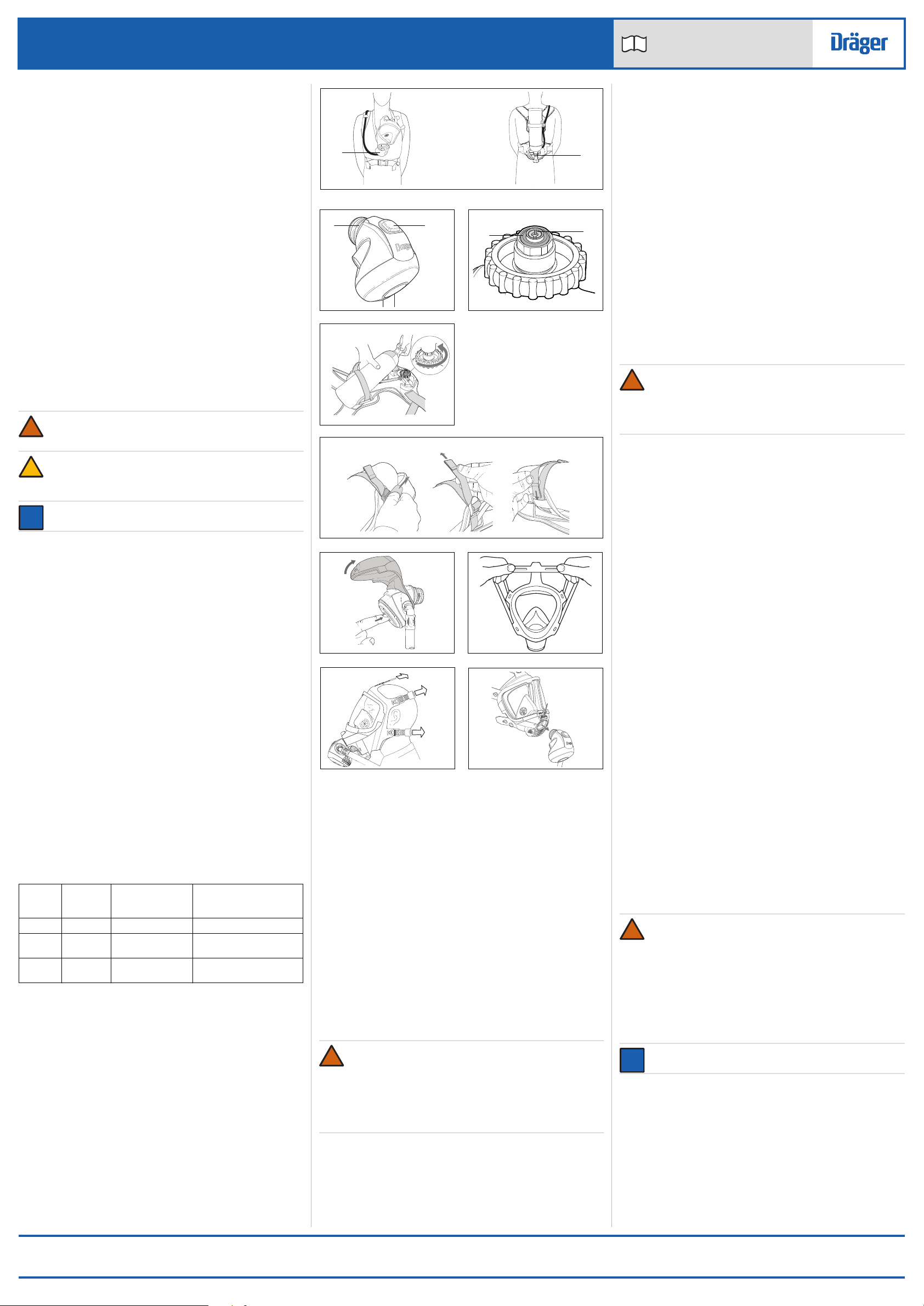
5. Referring to Fig 4, slide the cylinder through the cylinder strap and
align valve with the reducer. To prevent damage, ensure that the
cylinder remains clear of the hand wheel of the pressure reducer while
inserting the cylinder.
6. Align the cylinder with the centre of the carrying harness and then
screw the hand wheel of the pressure reducer on to the cylinder valve
(see direction arrow in Fig 4). Do not fully tighten.
7. Referring to Fig 5, take up the slack in the cylinder strap (1) to tighten
around the cylinder and then pull the strap through the buckle to
secure (2). Insert the loose end of strap into the guide loop (3).
8. Fully tighten the hand wheel hand tight. Do not use tools or over
tighten.
3.1.3 Functional testing
Leak test
WARNING
If the breathing apparatus fails to meet any of the standards or
parameters described in the functional tests, or if an immediate
leak is evident, there is a system fault. Report the fault to trained
service personnel or contact Dräger. Do not use the breathing
apparatus until the fault condition is rectified.
1. Ensure that the pointer of the cylinder pressure indicator is inside the
green area.
2. Positive-pressure systems: press the reset button (Fig 2, Item 2) to
switch off the valve.
3. Open the cylinder valve slowly, but fully, to pressurize the system, and
then close the cylinder valve.
4. Check for audible leaks. If there is any leak, investigate and repair the
leak before use (see Section 4). If necessary, use a soapy solution to
locate the leak.
5. Press the front button (Fig 6) (fold back the rubber cover to press the
button and then immediately refit the rubber cover) to fully vent the
system.
6. Positive-pressure systems: press the reset button (Fig 2, Item 2) to
switch off the valve.
3.1.4 Putting on the PAS Micro (ready position)
See also Fig 1 which shows the PAS Micro worn in the ready position.
1. Ensure the pointer of the cylinder pressure indicator is inside the green
area.
2. Fully loosen the shoulder straps and waist belt and put on the
apparatus.
3. Check that the shoulder pads are not twisted and take the weight of the
system on the shoulders by pulling the shoulder straps. Do not fully
tighten at this stage.
4. Close the waist belt buckle and pull the ends of the waist belt until it fits
securely and comfortably.
5. Pull the shoulder straps until the breathing apparatus rests securely
and comfortably on the hips. Do not over tighten.
6. Check that the face mask port, and the lung demand valve coupling
and O-ring are clean and undamaged.
7. Connect the lung demand valve to the face mask as follows:
○Push-in coupling: press into the port of the face mask until it
latches in position. Check the attachment by gently attempting to
pull the coupling apart.
○Screw-in coupling: screw into the port of the face mask and tighten
hand tight. When the lung demand valve is fitted to the face mask,
the connector can swivel to allow for head and body movement of
the wearer.
8. Put the neck strap of the face mask over the head, and then insert the
neck strap stud into the hole in the centre strap of the head harness.
3.2 During use
During use the PAS Micro is worn in the ready position until an escape is
necessary.
3.2.1 Putting on the face mask and escaping
WARNING
Correct fit of the face mask can only be achieved if the complete
mask seal makes contact with skin. Head hair, facial hair (including
beard stubble and sideburns), earrings, other facial piercings and
normal spectacles will interfere with the face mask seal and are not
permitted in the sealing area. Additionally, head hair that could
affect the face mask fit (buns, pony-tails, hairpieces, etc.) is not
permitted.
The duration available for escape starts from the time that the
wearer commences breathing from the air cylinder, and is
dependent on the capacity of the cylinder and the breathing rate of
the wearer.
NOTICE
Refer also to the face mask Instructions for Use.
1. Positive-pressure systems: press the reset button (Fig 2, Item 2) to
switch off the valve.
2. Open the cylinder valve slowly, but fully, to pressurize the system.
3. Detach the neck strap stud from the centre strap of the head harness.
4. Spread the head harness (Fig 7). Place the chin into the chin cup of
the face mask and pull the harness over the head locating the harness
centre plate on back of the head.
5. Referring to Fig 8, tighten both lower (1) and then upper straps (2)
evenly towards the back of the head. If necessary, tighten the centre
strap (3).
6. Breathe normally and immediately leave the hazardous area by the
shortest and safest escape route.
!
!
i
i
Dow Corning®and Molykote®are registered trademarks of Dow Corning Corporation. 3352432 (A3-D-P) 2 / 2
PAS®Micro Series
Escape repiratory protection equipment Instructions for use
i
The wearer must be in a safe area before the air cylinder is empty. When in a safe area, remove the lung demand valve from the face mask if necessary
and continue to breathe normally.
3.3 After use
WARNING
Do not remove the equipment until in safe area, clear of hazard.
CAUTION
Do not drop or throw down equipment as damage could occur.
1. Loosen the face mask straps.
○Positive-pressure systems: as the seal between the mask and the face is broken, press the reset button (Fig 2, Item 2) to switch off the valve.
2. Remove the face mask and fully extend all of the straps of the head harness.
3. Fully close the cylinder valve.
4. Press the front button (Fig 6) (fold back the rubber cover to press the button and then immediately refit the rubber cover) to fully vent the system.
5. Remove the lung demand valve from the face mask (Fig 9 – push-in coupling shown).
6. Open the waist belt buckle, lift the shoulder strap buckles to loosen the harness, and then remove the equipment.
7. Carry out the after use maintenance tasks in the maintenance table (see Section 5.1).
4 Troubleshooting
The troubleshooting guide shows fault diagnosis and repair information applicable to breathing apparatus users. Further troubleshooting and repair
information is available in Instructions for Use supplied with associated equipment (e.g. face mask and air cylinder).
Contact service personnel or Dräger when the remedy information indicates a service task, or if the symptom remains after all remedy actions have been
attempted.
5 Maintenance
5.1 Maintenance table
Service and test the breathing apparatus, including out-of-use apparatus, in accordance with the maintenance table. Record all service details and testing.
Refer also to the Instructions for Use for the lung demand valve, face mask and other associated equipment.
Additional inspection and testing may be required in the country of use to ensure compliance with national regulations.
Daily check – If the PAS Micro is held in a ready-for-use condition, check daily that the pointer of the cylinder pressure indicator is inside the green area.
Charge the cylinder if it is in the red area (see Section 5.2.2).
Notes
Dräger recommendations
1. Clean the equipment if it is dirty. If it the equipment has been exposed to contaminants, disinfect any components that come into direct and prolonged
contact with the skin.
2. These maintenance tasks may only be carried out by Dräger or trained service personnel. Details of the tests are contained in the Technical Manual
which is issued to service personnel that have attended a relevant Dräger maintenance course.
3. For type A check the O-ring on the lung demand valve. As a guide, lubricant should be felt on the fingers but not seen. If relubrication is required,
lightly apply Dow Corning®Molykote®111 (other lubricants are not tested and may damage the equipment).
4. Replace the sintered filter if a drop in reducer performance is observed during a flow check or if it is visibly damaged.
5. Replace the high-pressure connector O-ring if it is found to leak during functional testing or if the O-ring is visibly damaged.
6. Where the breathing apparatus is subjected to a high level of use (in training establishments etc.), reduce the overhaul period for the pressure
reducer. In these circumstances, Dräger recommend that the overhaul frequency should be less than 5,000 applications of use. An application of use
is defined as a single use of the fully assembled breathing apparatus, where the user breathes from the air cylinder. It does not include system
pressurization for pre-operational checks.
5.2 Maintenance tasks
5.2.1 Removing the cylinder
WARNING
High-pressure air release may cause injury to the user or other personnel near the breathing apparatus. Close the cylinder valve and fully vent
the system before attempting to disconnect the air cylinder.
1. Close the cylinder valve and press the front button (Fig 5) (fold back the rubber cover to press the button and then immediately refit the rubber cover)
to fully vent the system.
2. Loosen the cylinder strap.
3. Disconnect the cylinder valve from the pressure reducer.
4. Remove the cylinder. To prevent damage, ensure that the hand wheel of the pressure reducer remains clear of the cylinder.
Symptom Fault Remedy
High-pressure air leak or failed leak test Loose or dirty cylinder connector Disconnect, clean and reconnect the connector
and retest
Faulty hose or component Substitute user replaceable accessories and
retest
Air leak from medium-pressure hose connection
at the pressure reducer (safety relief valve)
Faulty O-ring, retainer, spring or pressure
reducer
Service task
High or low medium pressure Pressure reducer fault Service task
Component/
System
Task
Before
use
After
use
Every
month
Every
year
Every
six
years
Complete
equipment
Visual inspection (see Note 1 and Section 3.1.1) 
Functional test (see Section 3.1.3) 
Breathing cycle and static tests (see Note 2) 
Lung
demand
valve
Check push-in type connectors for lubricant (see Note 3) 
Pressure
reducer
Medium-pressure check (see Note 2) 
Inspect the sintered filter (see Note 2 and Note 4) 
Inspect the high-pressure connector O-ring (see Note 2 and Note 5) 
Overhaul. Contact Dräger for the Repair Exchange (REX) service (see Note 6) 
Cylinder Charge to correct pressure (see Section 5.2.2) 
Check the initial test date stamped on the cylinder 
Cylinder pressure test and recertification According to national regulations in the
country of use
Cylinder
valve
Overhaul At the time of cylinder recertification
!
!
!
5.2.2 Air cylinder charging
WARNING
Air quality for compressed-air cylinders must conform to
requirements of EN 12021.
●Refer also to the instructions supplied with the cylinder and the
charging unit for recharging the cylinder.
●Only charge compressed-air cylinders which:
○Conform to national standards.
○Feature the original manufacturer’s test date and test mark.
○Have not exceeded the test date indicated on the cylinder by the
last testing station.
○Are not damaged.
●To prevent ingress of moisture into the cylinder, ensure that the
cylinder valve remains closed until connected to the charging unit.
●Recharge to the rated working pressure of the cylinder. Dräger
recommend a charge rate of 27 bar/minute (rapid charging will
increase the temperature resulting in an incomplete charge).
●To prevent overcharging of the cylinder, Dräger recommend using a
pressure-limiting device on the charging compressor.
5.3 Cleaning and disinfecting
CAUTION
Do not exceed 60 °C for drying, and remove components from the
drying facility immediately when dry. Drying time in a heated dryer
must not exceed 30 minutes.
Do not immerse pneumatic or electronic components in cleaning
solutions or water.
If water is trapped and then freezes inside the pneumatic system
of the breathing apparatus (such as the lung demand valve),
operation will be impaired. Prevent any liquid from entering, and
thoroughly dry the breathing apparatus after cleaning to prevent
this from occurring.
For information about suitable cleaning and disinfecting agents
and their specifications refer to document 9100081 on
www.draeger.com/IFU.
Refer also to the Instructions for Use for the lung demand valve, face mask
and other associated equipment.
●Use only clean lint-free cloths
1. Clean the breathing apparatus manually using a cloth moistened with
cleaning solution to remove excess dirt.
2. Apply disinfecting solution to all internal and external surfaces.
3. Rinse all components thoroughly with clean water to remove all
cleaning and disinfecting agents.
4. Dry all components using a dry cloth, in a heated dryer or in air.
5. Contact service personnel or Dräger if disassembly of pneumatic
components is required
6 Storage
6.1 Storage preparation
●Extend the shoulder straps, waist belt and the straps of the face mask.
●For storage, place the face mask in a protective bag (contact Dräger
for supply of a suitable bag).
●Route rubber hoses in such a way that the bend radius is not too acute
and the hose is not stretched, compressed or twisted.
6.2 Storage conditions
●Store the equipment between -15 °C and +25 °C. Ensure that the
environment is dry, free from dust and dirt, and does not subject the
equipment to wear or damage due to abrasion. Do not store the
equipment in direct sunlight.
●Fix the breathing apparatus securely to any raised mounting point to
prevent it from falling.
7 Disposal
When required, dispose of the PAS Micro in accordance with national or
local regulations for waste disposal.
8 Technical data
High-pressure connector: 200 bar or 300 bar, standard G5/8” as per
EN 144-2.
!
!

Other Dräger Safety Equipment manuals

Dräger BG ProAir User manual

Dräger

Dräger BG ProAir User manual

Dräger PSS 4000 Series User manual

Dräger

Dräger PSS 4000 Series User manual

Dräger saver CF Series User manual

Dräger

Dräger saver CF Series User manual

Dräger PARAT C Series User manual

Dräger

Dräger PARAT C Series User manual

Dräger Panorama Nova PE Series User manual

Dräger

Dräger Panorama Nova PE Series User manual

Dräger X-plore 2100 User manual

Dräger

Dräger X-plore 2100 User manual

Dräger Bodyguard 1000 User manual

Dräger

Dräger Bodyguard 1000 User manual

Dräger Interlock 5000 User manual

Dräger

Dräger Interlock 5000 User manual

Dräger X-plore 4340 EN 140 User manual

Dräger

Dräger X-plore 4340 EN 140 User manual

Dräger PSS 7000 Series User manual

Dräger

Dräger PSS 7000 Series User manual

Dräger FPS 7000 RP User manual

Dräger

Dräger FPS 7000 RP User manual

Dräger SPC 4900 User manual

Dräger

Dräger SPC 4900 User manual

Dräger CPS 5900 User manual

Dräger

Dräger CPS 5900 User manual

Dräger PSS 3000 Series User manual

Dräger

Dräger PSS 3000 Series User manual

Dräger VarioGard User manual

Dräger

Dräger VarioGard User manual

Dräger SPC 2400 Flexothane User manual

Dräger

Dräger SPC 2400 Flexothane User manual

Dräger Panorama Nova RA User manual

Dräger

Dräger Panorama Nova RA User manual

Dräger Oxyboks KT User manual

Dräger

Dräger Oxyboks KT User manual

Dräger SPC 4800 User manual

Dräger

Dräger SPC 4800 User manual

Dräger X-plore 6000 User manual

Dräger

Dräger X-plore 6000 User manual

Dräger Oxy 3000/3000 MK II Trainer User manual

Dräger

Dräger Oxy 3000/3000 MK II Trainer User manual

Dräger Oxy 3000 MK III Trainer User manual

Dräger

Dräger Oxy 3000 MK III Trainer User manual

Dräger CPS 5800 User manual

Dräger

Dräger CPS 5800 User manual

Dräger Bodyguard 1500 User manual

Dräger

Dräger Bodyguard 1500 User manual

Popular Safety Equipment manuals by other brands

Safety 1st OutSmart Flex Lock HS271 user guide

Safety 1st

Safety 1st OutSmart Flex Lock HS271 user guide

ADRESYS ANGEL user manual

ADRESYS

ADRESYS ANGEL user manual

Supertech NITRO quick start guide

Supertech

Supertech NITRO quick start guide

Paramount Fitness WGG-RD-001 quick start guide

Paramount Fitness

Paramount Fitness WGG-RD-001 quick start guide

GWP Palmer Safety GUARDRAIL5 instruction manual

GWP

GWP Palmer Safety GUARDRAIL5 instruction manual

Ocean Signal rescueME Series user manual

Ocean Signal

Ocean Signal rescueME Series user manual

Safety 1st 48484 user guide

Safety 1st

Safety 1st 48484 user guide

Camp Safety DRUID manual

Camp Safety

Camp Safety DRUID manual

Alsina ALSIPERCHA instruction manual

Alsina

Alsina ALSIPERCHA instruction manual

Captron safecap A Operation manual

Captron

Captron safecap A Operation manual

ROCKY RESCUE RKD0086 USER INSTRUCTION, SAFETY AND TRAINING GUIDE

ROCKY

ROCKY RESCUE RKD0086 USER INSTRUCTION, SAFETY AND TRAINING GUIDE

SECUMAR SURVIVAL 220 manual

SECUMAR

SECUMAR SURVIVAL 220 manual

Honeywell SPACEL 3000 Series user guide

Honeywell

Honeywell SPACEL 3000 Series user guide

Hurst Jaws Of Life eDRAULIC SC 250 E2 instruction manual

Hurst Jaws Of Life

Hurst Jaws Of Life eDRAULIC SC 250 E2 instruction manual

Spencer Life Guard user manual

Spencer

Spencer Life Guard user manual

DOCK LIFEGUARD DOCK LIFEGUARD user guide

DOCK LIFEGUARD

DOCK LIFEGUARD DOCK LIFEGUARD user guide

Petzl L22R 025 instruction manual

Petzl

Petzl L22R 025 instruction manual

Bornack LORY CLIMB user manual

Bornack

Bornack LORY CLIMB user manual

manuals.online logo
manuals.online logoBrands
  • About & Mission
  • Contact us
  • Privacy Policy
  • Terms and Conditions

Copyright 2025 Manuals.Online. All Rights Reserved.