DSC GS3055-IG User manual

GG
GG
GGSM/GPRS Alarm Communicator
EE
EE
EComunicador de Alarma GSM/GPRS

2GS3055-I
G
E
Fig. 1 - Parts - Partes
/2&.
23(1
!"
#$" #$"%
&'#& '
!(& '(
!)** !**
+ ,
- . !/
-0 ,1
,0 $,
$, ,
2*3425*-0 -12*3426*
4'!
!

3
G
TABLE OF CONTENTS ...................................................... 3
INTRODUCTION ................................................................ 4
FEATURES ........................................................................... 4
Technical Specifications .......................................................... 4
Description .............................................................................. 6
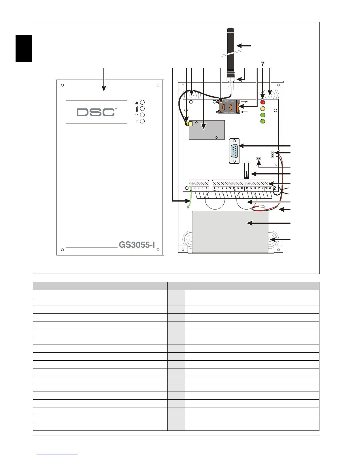
IDENTIFICATION OF PARTS ........................................... 6
INSTALLING THE DEVICE ............................................... 6
CONNECTING THE DEVICE ............................................. 7
STATUS LEDS ................................................................... 7
OPERATING PRINCIPLES ................................................ 8
Simulated Land Line ................................................................ 8
Sequence ..................................................................................... 8
SMS function .......................................................................... 8
ContactID Mode ..................................................................... 8
Function Priority ...................................................................... 9
Simulated Land Line Priority ........................................................ 9
SMS or Contact ID Priority ............................................................. 9
ContactID Event Priority ................................................................ 9
ACTIVATING THE OUTPUTS ............................................. 9
Activating/Deactivating Automatic Outputs .............................. 9
Activating/Deactivating Remote-control Outputs ...................... 9
Bistable Outputs (for appliance management) ........................... 9
Monostable Outputs (for appliance management) .................. 10
PROGRAMMING THE DEVICE ....................................... 10
Viewing the Device Settings ...................................................... 10
Downloading the Device Settings ............................................ 10
Preliminary operations .............................................................. 10
Telephone Page ..................................................................... 11
Telephone Numbers ................................................................... 11
Prefix ........................................................................................... 11
Digit to Remove ........................................................................... 11
SMS Dialer Page .................................................................. 11
Main window ............................................................................... 11
Priority ........................................................................................ 12
Pay-as-you-go Balance message ............................................ 12
Periodic message ...................................................................... 12
Outputs Page ........................................................................ 12
Output Settings .......................................................................... 12
Access Code .............................................................................. 12
Contact ID Page ................................................................... 13
Telephone numbers to call ....................................................... 13
Events description ..................................................................... 13
Contact ID default ...................................................................... 13
Send over GPRS ........................................................................ 13
Periodic Reports ........................................................................ 13
GPRS page .......................................................................... 14
Access Point Name (APN) .......................................................... 14
Receiver IP address and Port ................................................... 14
APNs User Name and Password .............................................. 14
Telephone numbers to decode ................................................ 14
DNIS ........................................................................................... 14
Account code ............................................................................. 14
Calls Page ........................................................................... 14
Load button ............................................................................... 14
Received Calls .......................................................................... 14
Missed Calls ............................................................................... 14
Dialled Calls .............................................................................. 14
Status Page .......................................................................... 15
Status section ............................................................................. 15
Inputs section ............................................................................. 15
Outputs section .......................................................................... 15
Events section ............................................................................ 15
Send next periodic message on .............................................. 15
Send next periodic report on ................................................... 15
Clear call queue ........................................................................ 15
INFORMATION FOR THE USER ..................................... 15
GSM Network Calls ............................................................ 15
Further Information ................................................................ 15
ATTENTION
In order to avoid the overload of the panel aux. power output
this Device is equipped with a limiter for the drawn supply current.
This current limiter fixes to 120 mA the maximum current drawn by the Device
and the current peaks will be supplied by the back-up battery.
Therefore, the connection of a charged battery to this Device is mandatory for its proper operation.
The current limiter can be bypassed by moving the jumper JP3 (part n. 8 of the Identification of the Parts)
downward (when jumper JP3 is found upward - factory setting - the current limiter is active),
in this way all the current requested from this Device (700 mA Max.) will be supplied by panel aux. power output,
therefore, it must be properly determined the max output power of panel.
The current limiter MUST BE BYPASSED if it is previewed that this Device
transmits for long periods of time on GSM/GPRS network.
Otherwise the battery back-up could be disharged excessively
and may not ensure the correct transmission of alarms.
If the limiter is bypassed and the panel is not able to supply the necessary current for the proper operation of this Device,
use a 13.8 V_, ±2%, 1 A, external power supply.
The BACK-UP BATTERY MUST ALWAYS BE CONNECTED TO the DEVICE,
in any case of the current limiter is ON or OFF.
TABLE OF CONTENTS

4GS3055-I
G
INTRODUCTION
The device is a backup wireless communicator that sends alarm system information to a System III or System II receiver through a GSM/
GPRS wireless network. The device is available in two models that are different for the operating frequency only:
GS3055-IG = 850/1900 MHz
GS3055-IGW = 900/1800 MHz.
This manual provides programming and operating instructions for both the device GSM/GPRS alarm communicators. Information relating
to a specific model will be denoted by the applicable model number within the text. The term "Device" is used to describe functionality that
is applicable to both models.
,,
,,
,This Device is fixed and shall be installed by Service Persons only (service person is defined as a person having the
appropriate technical training and experience necessary to be aware of hazards to which that person may be exposed
in performing a task and of measures to minimize the risks to that person or other persons). It shall be installed and
used within an environment that provides the pollution degree max 2, over voltages category II, in non-hazardous,
indoor locations only. This manual shall be used with the Installation Manual of the alarm control panel. All instructions
specified within that manual must be observed.
FEATURES
Technical Specifications
The input voltage to this Device can be drawn from the Control Panel or provided by an external power supply rated for the application.
Simulates land line
Switches automatically to GSM Network in the event
land line trouble (line down)
Manages and signals Incoming/Outgoing calls
GSM signal indicator
4 programmable OC Outputs
Houses 12 V / 1.2 Ah battery (optional)
Tamper protection contact
Land line overvoltage protection
Dual-Band
4 Input Lines
SMS Alerts
Supports Contact ID communication format from a connected control
panel for communication over the GPRS network
GPRS/Internet communication with Sur-Gard System III / II
13 SMS Messages (2 messages per Input Line and 5 Status
messages)
8 phone numbers (max. 20 digits) programmable for SMS Dialer
4 phone numbers programmable for Contact ID Dialer
Up to 95 phone numbers (max. 20 digits) can be programmed to
manage remote control of the OC Outputs
Remote control of the OC Outputs via SMS and/or over-the-phone
after caller recognition
Pay-As-You-Go Balance message (for pre-paid SIM Cards)
HVUWR
WRHV!UHR"DW#$W%&W'
R!UDH$VD(R&HUV!$HV)
"* +3,-..D(WHUD$#DWWHU%
UH/!UH()RU"* +3,-1)
VHD$H(0UH'DU1HD#$HW%H0UDWH(2*'
"*
"*
D3D$D#$H0RHR$$HWRUW%HV&W'H(
WR1UR!(0UDWH("*
! 2456 2456
(7
"#$ " 8W)R8RD9D#$H
# %&'
( :R'"
# '(
WR;.
) 99""299'
*&%& 12R6

5
G
Fig. 2 - Wiring Diagram
/, 2 2 2 2
/ / / /
%$77(5<
!!
([WHUQDO
3RZHU
6XSSO\
50
5HOD\
:$51,1*
!
"#$%&'#('$)'
*+,*
-
!
!"#$
% &&#"' (#)
*"#!#' &#!&#%
') )" %#)&
"#
5-

6GS3055-I
G
Description
This Device manages SMS and Central Station transmissions and can simulate the land line in the event of trouble (land line down) or
even substitute the land line completely in areas where the GSM service is provided and where the land line is not available.
This Device has capability of communicating alarm signals via the GPRS data network. The capability enables a fast reliable path to central
stations equipped with a Sur-Gard System III or System II receiver.
By connecting this Device to a control panel's standard PSTN interface, telephone based Contact ID signals are decoded and seamlessly
routed through the GPRS network to any of the compatible receiver options.
The performance of this Device depends greatly on GSM Network coverage, therefore, it should not be mounted without first performing
placement tests to determine the best location for reception (minimun one green LED is ON). This Device has 4 Input lines which can be used to
activate SMS and/or Contact ID transmissions such asTrouble alert, Periodic messages or Pay-As-You-Go Balance (for pre-paid SIM Cards).
This Device has 4 Outputs which can be set up from remote locations or used for status signalling.
Due to the characteristics of GSM Networks, this Device can activate only as intended and cannot be used as a modem for fax/data
transmissions or for teleservice operations.
IDENTIFICATION OF PARTS
The numbers in square brackets []in this manual refer to the main parts of this Device (see Fig. 1) described in this section.
INSTALLING THE DEVICE
,,
,,
,Do not route any wiring over circuit boards. Maintain at least 1” (25.4mm) separation. A minimum 1/4” (6.4mm)
separation must be maintained at all points between Power Limited wiring and all other Non-Power Limited wiring.
Route wires as indicated in Figure 1.
This Device shall be installed by qualified SERVICE PERSONS only. This Device must be installed
indoors in a non-hazardous location. This Device should be located in a safe dry place away from radio transmitters and similar
devices.
,,
,,
,Test the GSM Network reception before mounting this Device in the proposed placement.
1. Remove the screw and the front cover [1].
2. Fit the antenna [2] (ensure that the bolt [3] is fastened tightly).
3. Using the connector [5], connect the GSM Module [17].
4. Following the arrow on the board, insert the SIM-CARD [6] face down in the SIM holder (see Figure 1).
GThe SIM-CARD PIN must be disabled.
5. Checking Signal Strength
- Connect battery to the RED and BLK flying leads.
- Connect DC Power source to +/- 12V terminals.
- Allow unit to power up
- When the green LEDs turn on, ensure that the bottom green LED is ON. If both are ON, it indicates perfect coverage.
- If the bottom green LED is blinking, the signal level is not acceptable, reposition and retest the Device until an acceptable signal
strength is found.
6. Using the cabinet, mark the 4 screw locations then drill the anchor screw holes.
GCheck for cable conduits and water pipes before drilling.
7.Using anchor screws (not included), mount the cabinet to the wall.
8. Lay the cables, then pull them through the cable entry [14].
9. Complete the connections on the terminal board [12].
10. Using the 4 scews, reattach the front cover [1] securely to the cabinet.
,,
,,
,Connect power and Telco circuit only after the cabinet has been secured to the building or structure and has been
connected to the protective earth ground. Before inserting or removing the SIM card, please ensure the unit is
powered down.

7
G
CONNECTING THE DEVICE
This section describes the various terminals. Fig. 2 shows a typical wiring diagram.
--
--
-(1) Earth Ground: This terminal must be connected to the Mains Earth, in order to comply with the Telecommunications Network
Safety Standards (Overvoltage Protection Requirements).
LE (2-3) External telephone line: These terminals can be connected to the land line.
LI (4-5) Internal telephone line: These terminals must be connected to the L.E. terminals of the control panel.
MM
MM
M(6-14) Negative: Power Supply.
O1 (7), O2(8), O3 (9), O4 (10) Programmable Open-Collector Outputs: These outputs can be activated either by programmed
events (Automatic Mode) or by SMS text messages (Remote Mode), refer to “Activating the Outputs” for details. The maximum current
sink of each OC Output must not exceed 50 mA
+OC
(11) Common terminal for Open-Collector Outputs: Common power-supply terminal (12 VDC / 200 mA) for all Outputs (O1, O2,
O3, O4).
AS (12-13) Tamper: These terminals are connected in series to the Tamper microswitch [11]. They will be closed when the cabinet is
properly closed, and will open when the front cover is removed.
L1 (15), L2 (16), L3 (17), L4 (18) Programmable Input line: These terminals can be set up to activate the SMS and Contact ID
transmission functions.
12V(19-20) Device power supply: These terminals must be connected to a rated power supply. If the Device power supply is
drawn from a Control panel, ensure that the required current (700 mA) is protected by a resettable fuse or similar
device.
Once the connections are completed, connect the Red and Black wires [13] to a 12 V, 1.2 Ah battery.
,,
,,
,To ensure proper operation of this Device, the connection of a battery is needed to provide temporary additional
current during normal operation (see Fig. 2)
,,
,,
,This Device must be connected to an external power supply and to a battery. This device must be connected to a
proper Earth Ground (see Fig. 2).
,,
,,
,When disposing of batteries, follow the instructions and and precautions printed on the batteries, and contact your
municipal offices for information on the disposal of used batteries.
STATUS LEDS
This Device has 4 status LEDs.
,,
,,
,The top two LEDs will blink during the Initializing and Programming phases.
The following section describes the status LEDs.
GRED — This LED is Normally OFF, it will blink in the event of trouble. This LED will switch ON within 3 minutes in the event of GSM
Module [17] trouble, or when the GSM Network is unavailable (NO SERVICE).
On power-up, this Device will check for certain trouble conditions to be met in the order listed below. It will indicate the status of last
unchecked condition with the corresponding number of flashes of the RED LED.
Once the highest priority trouble condition has been cleared, the next highest priority trouble condition will be displayed.
1 flash - Battery Trouble (No or Low Battery)
2 flashes - Radio/SIM Failure
3 flashes - GSM Network Problem
4 flashes - Insufficient Signal Strength
5 flashes - “Not available”
6 flashes - Receiver Not Available
7 flashes - Power Supply Trouble
8 flashes - Supervising receiver absent
Off - No Troubles
tYELLOW — This LED will switch ON when the interface switches to the GSM Network (due to land line trouble). This LED will Blink
slowly in the event of an incoming or outgoing voice call (regardless of the operating status of the land line). This LED can also blink
quickly once (GPRS TX) or twice (GPRS RX).
YGREEN (Top) — When this LED is ON, the reception is optimal. This LED will switch ON only when the other GREEN LED is ON.
yGREEN (Bottom) — If this LED is OFF and the RED LED is ON, the GSM Network service is unavailable (NO SERVICE).
This LED will Blink when the GSM Network reception is bad, if this occurs, only SMS transmissions will be possible. If this LED is ON,
the Device will be able to manage all telephone communications.

8GS3055-I
G
OPERATING PRINCIPLES
Simulated Land Line
The Simulated land line provides the alarm control panel (with dialer interface) with a backup line in the event of PSTN line trouble. If the
voltage on the land line terminals (LE) drops below 3 V for a period of between 10 to 45 seconds (depending on the device connected
to the LI terminals), this Device will switch the connected telephone device to the GSM Network for a full 15 minute interval, at the end of
this interval, it will check the land line:
—if the land line has been restored, it will switch the connected telehone device back to the land line;
—if the land line is still down, it will continue to simulate the land line until it is restored.
This Device will not switch during ongoing calls. The simulated line will provide the line ring voltage for incoming calls and will decode
DTMF dialling
,,
,,
,This Device is unable to decode Pulse dialling.
The Function Priority (to be selected during the programming phase) will determine how this Device manages communications (SMS
and ContactID) and calls from the telephone device connected to the LI terminals (e.g. Control panel).
Sequence
When alarm is triggered, the Alarm Panel goes off-hook.
The Device will assert dial tone.
Control Panel dials the number of the central station. Ensure the alarm panel inserts a minimum 1-second pause, or has dial tone
search enabled before dialing the number.
The Device detects the DTMF dialing and stops dial tone.
The Device will send the required Contact ID dual tone handshake.
After receiving the handshake, panel transmits alarm message in DTMF format.
The Device decodes and transforms DTMF digits into the packet and sends it to the Central Station Receiver over the GPRS network.
The receiver acknowledges the alarm and sends command to the Device to generate the corresponding 1400 hz kiss-off signal for
800ms minimum.
After the Device generates kiss-off, the panel goes on-hook if no more alarms need to be sent, or it can send the next alarm.
SMS function
This operating mode allows this Device to send text messages to 8 telephone numbers. The messages can be associated with the following
events:
Alarm signals on the 4 Programmable Input lines: 2 preset messages — Alarm and End of Alarm.
Land Line Test: 2 preset messages — Line down and Line restored.
Power supply Test: 2 preset messages — Trouble and Trouble clear
Periodic message: 1 message to be sent at regular intervals (accepted values 1 through 999999 minutes).
,,
,,
,The SMS messages will be sent to the programmed numbers when the respective events occur.
ContactID Mode
This operating mode will allow this Device to send calls to the Central Station. The events are being generated using four inputs L1 - L4.
Alarm signals: require Event Codes and Customer Account Codes
Status signal, with a Customer Account Code
Land Line Test:
Power supply Test:
Call queue full
Periodic report (to be sent at regular intervals).
,,
,,
,The Contact ID reports will be sent when the respective events occur.

9
G
Function Priority
Simulated Land Line Priority
If the equipment connected to the LI terminals (e.g. Control panel) tries to engage the line, this Device will interrupt any ongoing
communications (SMS or ContactID) in order to send the calls generated by the device. This Device will restart the interrupted communications
when the equipment disengages the line.
SMS or Contact ID Priority
If the equipment connected to the LI terminals (e.g. Control panel) is using the GSM Network (through this Device) when an SMS or
ContactID associated event occurs, this Device will interrupt the ongoing call and send the respective SMS message or ContactID report.
ContactID Event Priority
If several events occur contemporarily, the respective messages will be sent in chronological order. If an event is associated with a
ContactID report and an SMS communication, priority will be given to the ContactID report.
ACTIVATING THE OUTPUTS
This Device has 4 outputs programmable as Automatic (outputs with this attribute will activate in response to the associated events) or
Remote Control (outputs with this attribute can be activated manually from remote locations by means of SMS messages or calls from
enabled telephone numbers).
Activating/Deactivating Automatic Outputs
The PGM outputs can be activated automatically by the following events:
Land line trouble (line down)
GSM Module trouble
GSM Network trouble (Limited/No Service)
Power supply trouble (external power supply or battery)
Incoming call
Outgoing call
Enablement of remote programming
Fail to communicate for internal events (FTC)
,,
,,
,Once an output has been activated automatically, it will not restore its state until all the causes of activation clear.
Activating/Deactivating Remote-control Outputs
The OC outputs can be programmed as BISTABLE (activated/deactivated by means of an SMS text message or Remote Control
number) or MONOSTABLE (activated by means of SMS text messages or Remote Control numbers). Once a Monostable output has
been activated, it will not deactivate until the programmed ON Time expires. Each output can be set up to provide a feedback signal (ring
or SMS text message).
,,
,,
,For further information regarding the terms “Access Code” and “Output Label” (used in the following section), refer
to the “Outputs Page” in the “Software” section.
Bistable Outputs (for appliance management)
Bistable OC outputs can be activated in 2 ways.
1. By sending a case sensitive SMS text message containing the respective Access Code, placed between pound signs (#), and the
Output Label (e.g. GATE) followed by =ON, as follows:
#ACCESSCODE#OUTPUTLABEL=ON (example: #AZ55#GATE=ON)
2. By sending a cost-free call from a preset Remote Control number.This Device will activate the respective output without answering
the call.
,,
,,
,Bistable OC outputs can be deactivated by sending a case sensitive SMS text message containing the respective Access Code
placed between pound (#) signs and Output Label (e.g. GATE) followed by =OFF, as follows:
#ACCESSCODE#OUTPUTLABEL=OFF (example: #AZ55#GATE=OFF)

10 GS3055-I
G
Monostable Outputs (for appliance management)
Monostable OC outputs can be activated in 2 ways.
1. By sending a case sensitive SMS text message containing the respective Access Code placed between pound (#) signs and Output
Label followed by “=ON” or “=OFF”, as follows:
#ACCESSCODE#OUTPUTLABEL=ON
#ACCESSCODE#OUTPUTLABEL=OFF
2. By sending a cost-free call from a preset Remote Control number. This Device will activate the output concerned without answering
the call.
,,
,,
,Monostable OC outputs deactivate (switch OFF) automatically when the programmed ON Time expires.
PROGRAMMING THE DEVICE
,,
,,
,For proper function of this Device, use a 32 K SIM CARD (or higher).
,,
,,
,Disconnect the telecommunication line before connect the PC to the RS232 port.
This section contains the programming instructions using the GS3055 Software Application. This programming method requires the
connection of a Null-Modem cable (see Fig. 3) to the RS232 input [10] of this Device and the computer COM port.
Once the Null-Modem cable has been connected, set the computer COM port through the Settings->Serial Port option from the Menu.
Viewing the Device Settings
To view the Device settings on the screen, use the Programming->Load option from the Menu.
Downloading the Device Settings
Once programming has been completed (or an uploaded file containing existing data has been modified), download the data into the
Device, using the Programming->Download option from the Menu.
Preliminary operations
When the application starts, you will be presented with the Main window showing two sections on the left hand side.
zFolders: This section will allow you to click on the various Programming and Control Pages.
zCustomers: This section will allow you to delete or retrieve configuration data, as follows:
1. Using the right button on the mouse, click on the Customer’s name.
2. Click Load to upload the respective data from the Hard-Disk, or Delete to delete the data configuration.
You can load the configuration data by double clicking the respective name field.
You can list Customers in alphabetical or code order by clicking the heading of the column concerned.
,,
,,
,To start the configuration of a new Customer, click on File->New Customer then select the device (e.g. GS3055-I) from the product
list in the successive window.
The configuration data is presented on 4 pages, a further 2 pages (Calls and Status) are for “Supervisory and Control” purposes. All
the pages are described in detail in this section.
Fig. 3 - Null-Modem cable for programming via PC

11
G
Telephone Page
The Telephone Page phonebook holds 95 telephone numbers.
,,
,,
,The first eight numbers in the phonebook will also be used for the SMS functions.
Telephone Numbers
zDescription: enter an alphanumeric string of up to 20 characters.
zNumber: enter a telephone number of up to 20 digits (only digits and “+” signs are accepted).
zRemote Control Numbers:select the telephone numbers which will be able to control Outputs 1, 2, 3 and 4 over the phone. The
telephone numbers cannot be selected in open order, therefore, if telephone numbers 1 and 6 are selected, telephone numbers 2,
3, 4 and 5 will be selected automatically.
zDial.: This memorandum column shows the SMS Dialer telephone numbers (selected on the SMS Dialer Page from the first 8
telephone numbers in the phonebook).
Prefix
IMPORTANT: This Device will prefix the digits entered in this field to all the telephone numbers dialled through the GSM Interface
function.
If necessary enter a Prefix (maximum 4 digits) in this field. If no Prefix is required, leave this field empty.
Digit to Remove
If this Device is connected downstream to a switchboard, the telephone numbers (programmed on the Control panel) must be preceded
by the switchboard number (normally one digit). As the switchboard number is not required when calls are sent over the GSM Network,
it must be removed from the digits which form the telephone number. Enter the number of digits that form the switchboard number (e.g. if
switchboard number is 01, enter 2 in the ‘Digits to remove’ field, as 2 numbers form the switchboard number).
SMS Dialer Page
This page will allow you to program the SMS Dialer functions and Messages and also set up the ‘Special Functions’ of the 3 Input lines.
,,
,,
,The configuration data on on this page concerns the first eight telephone numbers entered on the “Telephone” page.
To send the SMS it is necessary enter a Customer Code (e.g. 1111) for the relevant event (see the column ‘Customer
Code’ in the Contact ID Page)
Main window
The column on the left-hand side of the Main window shows the events which, if duly programmed, will generate two SMS text messages: one
for activation and the other for restoral (the ‘Periodic message’ can generate the activation message only).
zPolarity: (this column shows the events which unbalance the 4 Input lines), select the Standby polarity of the Inputs
— H-Normally Open or L-Normally Closed.
zTelephone Numbers: click (tick) the check boxes of the numbers to be called when the respective event occurs.
zSMS: write the Activation and/or Restoral message to be sent when the respective event occurs (maximum 100 characters). If no
message is required, leave the respective box empty.
zServ: If this option is enabled, unbalance (on Input Lines 1, 2 and 3) will generate actions instead of calls. Two actions can be set up
for each Input Line, as per the following table.
*%&
*
"+)
7
%
!"
*,
7--'

12 GS3055-I
G
Priority
This section will allow you to select the operating priority of this Device: Interface (at default) or SMS Dialer/Contact ID Communicator.
Pay-as-you-go Balance message
,,
,,
,NOTE: The Manufacturer shall not assume responsibility for Pay-as-you-go credit services managed by GSM Network
Providers.
If you enable this option, an SMS text message — containing information provided by the GSM Network regarding the end-user’s credit
balance — will be sent to the first number in the Telephone Number list. Enter the number of telephone calls (ContactID reports and/or
outgoing SMS text messages) this Device must allow before checking the Pay-as-you-go balance.
zPay-As-You-Go Balance message - If you click on this button the application will open a window showing the remaining credit balance (if
this service is managed by your network provider), or a message indicating that this service is not available.
The default string in the 'Pay-As-You-Go Balance message' field (*123#) is supported by most major service providers.
Periodic message
This section will allow you to set up the Periodic message options.
zDate of first Periodic message - Select the Date of the first Periodic message.
zTime of the first Periodic message - Select the Time of the first Periodic message.
zInterval - Enter the interval (DD-HH-MM) between each Periodic message. Accepted DAY values: 0 to 693.
,,
,,
,ATTENTION - If Input Line 2 is assigned to Special functions (Column A), transmission of the Periodic message will be
subordinate to ‘Unbalance’ on Input Line 2 (refer to the ‘Special functions’ table). If this occurs, the Date and Hour of
the Periodic message will be irrelevant.
To send the SMS it is necessary enter a Customer Code (e.g. 1111) for the relevant event (see the column ‘Customer
Code’ in the Contact ID Page).
If the external power supply (connected to terminals [+12V]) and battery power supply drop at the same time, the Device
must be re-programmed after the power supply is restored, otherwise the time set for the Periodic Message could NOT be
respected.
Outputs Page
This page will allow you to set up and control the outputs.
Output Settings
zPolarity: select the polarity of the output: H-Normally Open L-Normally Closed.
zFor Land Line Trouble, GSM Trouble, etc.: select the events that will activate the outputs.
zReserved Output: If this option is selected, all other events assigned to the output in this section will be ignored. Select this option, if
the output concerned is to be used for Remote control purposes (refer to “Activating and Deactivating and Remote Control Outputs”).
The following options will affect Reserved Outputs ONLY.
Output Label - Type in the label (max. 8 characters) of the appliance (e.g. Gate) which is to be remote-controlled via SMS.
Output feedback - Select the type of feedback signal (None, Ring or SMS) to be sent when the respective output activates.
If the Output Label field is empty, the SMS option will not be available.
Monostab. - Under normal circumstances, these outputs hold active status until they receive a deactivation command. If
automatic deactivation is required, it will be necessary to program the ON Time (i.e. the time the output will hold active status).
ON Time (sec.) - Enter the required ON Time in seconds (accepted values 2 to 254 seconds). If the output has been
programmed as Monostable, this value will determine the amount of time the output will hold active status before restoring to
standby.
Access Code
Type in the code (maximum 4 alphanumeric characters) which will allow the user to control the outputs over-the-phone.

13
G
Contact ID Page
This page will allow you to set up the Contact ID function.
Telephone numbers to call
Four telephone numbers of up to 20 digits (digits and + signs).
This Device will try each telephone number 3 times before considering a call unsuccessful and quitting.
,,
,,
,The Contact ID Codes will be sent to the first number (with Contact ID reporting protocol) that answers the call.
Events description
zCustomer Code - type in a 4 character code (accepted values: digits and the letters A, B, C, D, E and F).
To send the SMS it is necessary enter a Customer Code (e.g. 1111) for the relevant event.
zEvent Code - type in the Contact ID to be transmitted when the respective event occurs.
zSend - select (tick) the events to be sent.
Contact ID default
Click on this button to assign the following Event Codes to the events manage by this Device.
Event Description Event Code Sur-Gard System III / II Description
Input 1 activation E 110 FIRE ZONE 001
Input 1 Restoral: R 110 FIRE ZONE 001
Input 2 activation: E 120 Panic Alarm ZONE 002
Input 2 Restoral: R 120 Panic Alarm ZONE 002
Input 3 activation: E 130 Burglary ZONE 003
Input 3 Restoral: R 130 Burglary ZONE 003
Input 4 activation: E 150 24 HOUR (AUXILIARY) ZONE 004
Input 4 Restoral: R 150 24 HOUR (AUXILIARY) ZONE 004
PSTN Line down: E 351 TELCO 1 FAULT 000
PSTN Line Restoral: R 351 TELCO 1 FAULT 000
12V INPUT LOSS: E 337 EXP. MOD. DC LOSS 000
12V INPUT RESTORAL: R 337 EXP. MOD. DC LOSS 000
LOW BATTERY ALERT: E 338 EXP. MOD. LOW BAT 000
LOW BATTERY RESTORAL: R 338 EXP. MOD. LOW BAT 000
PERIODIC REPORT: E 603 Periodic RF Xmission 000
GSM UNIT ACTIVATION: R 552 Radio Xmitter Disabled 000
GSM INTERNAL BUFFER FULL: E 624 EVENT LOG OVERFLOW 000
FTC EVENT: E 354 FAILURE TO COMMUNICATE 000
FTC RESTORAL: R 354 FAILURE TO COMMUNICATE 000
Send over GPRS
If this option is enabled, this Device will only communicate Contact ID events via the GPRS network.
Periodic Reports
This Device can be programmed to send Periodic Contact ID reports. This section will allow you to select the Date and Time of the first
periodic report and the Interval between reports.
If the external power supply (connected to terminals [+12V]) and battery power supply drop at the same time, the Device
must be re-programmed after the power supply is restored, otherwise the time set for the Periodic Report could NOT be
respected.

14 GS3055-I
G
GPRS page
This page outlines the GPRS configuration options.
Access Point Name (APN)
Enter the Access Point Name of the GPRS service provider being used. (example: ibox.tim.it) Please contact the GPRS service provider
for this information.
Receiver IP address and Port
Enter the primary (mandatory) and back-up (optional) receiver IP addresses and port numbers. Use the same IP address and Port that
is found in the 'Receiver Remote Port' section of the Sur-Gard SYSTEM III and SYSTEM II.
APNs User Name and Password
Some providers may require a user name and password to validate communication. If needed, enter this information here.
Telephone numbers to decode
In this section you may enter up to two telephone numbers dialed by the panel that will be recognized by the device when called to trigger
GPRS communication. If a number is programmed, any time a number dialed does not match one of the phone number entered, the call
will be routed through the voice channel. Leaving it blank will route all calls to GPRS.
DNIS
If required, enter the Dialled Number Identification Service number. This should be the same DNIS number received at the Central Station
when this panel communicates through a land-line.
Account code
An account code is required for communication with Sur-Gard SYSTEM III or SYSTEM II receivers. Enter the Account Code in this field.
Calls Page
This page will allow you to view on the screen the Dialled, Received and Missed calls.
,,
,,
,Each section can store a maximum of 10 calls. If the number of calls exceeds this limit, this Device will make space
automatically by deleting the oldest calls.
Load button
To view the Dialled, Received and Missed calls, click the Load button. Depending on programming, some telephone numbers may not
have Caller ID.
Received Calls
If this Device is connected to a Control panel or another telephone device, this section will allow you to view the calls received by this
Device.
Missed Calls
This section will allow you to view any unanswered incoming calls.
Dialled Calls
This section will allow you to view any calls dialled by this Device whether in Contact ID Communicator mode and/or GSM Interface mode.

15
G
Status Page
This page will allow you to monitor and control in real-time all the Device functions and, if not previously done, unblock the SIM CARD PIN.
,,
,,
,ATTENTION: This page is updated every 5 seconds.
Status section
This section shows the GSM Module data. This virtual display shows the GSM Network Provider, the Device battery charge (for the
precise level, position the mouse arrow on the battery icon for a several seconds) and GSM signal reception (indicated by 10 bars).
The virtual Comunication LED is usually GREEN. It will turn RED in the event of a breakdown in communication between the software
and this Device. If it turns AMBER, this Device is either reading the SIM CARD or receiving/making a telephone call, under these
circumstances the status update will be suspended temporarily.
Inputs section
This section shows the status of each of the 4 Inputs (GREEN LED = Input balanced; RED LED = Input Unbalanced) and any Special
functions associated with the Inputs.
Outputs section
This section shows the status of each of the 4 Outputs (GREEN LED = Output in standby; RED LED = Output activated). If any of the
Outputs has been set up as “Reserved” (refer to “Outputs page”), RED LED On, it will be possible to activate/deactivate the Outputs
in real-time by right-clicking the respective Polarity option and selecting the Activate/Deactivate sub-option.
Events section
This section shows the events as they occur (RED LED On).
Send next periodic message on
This section shows the Date and Time of the next periodic SMS text message (refer to the SMS dialer page).
Send next periodic report on
This section shows the Date and Time of the next periodic Contact ID report (refer to the Contact ID Communicator page).
Clear call queue
This button will allow you to interrupt any ongoing calls and stop the outgoing call queue.
,,
,,
,This option is available ONLY when this Device operates in SMS Dialer/Contact ID Communicator mode.
INFORMATION FOR THE USER
GSM Network Calls
If this Device is connected to a telephone, it will be possible to make calls on the GSM Network.
Further Information
Refer to the following sections for further information:
STATUS LEDs
OPERATING PRINCIPLES
ACTIVATING THE OUTPUTS

16 GS3055-I
E
INDICE
ATENCIÓN
Para evitar la sobrecarga de la salida de alimentación de los paneles, este aparato se ha equipado
con un limitador para el consumo de corriente.
Este limitador fija en 120mA el consumo máximo del equipo y los picos de consumo serán absorbidos de la batería de soporte.
Por lo tanto, la conexión de una batería es obligatoria para un funcionamiento adecuado.
El limitador de corriente puede ser anulado situando el puente JP3 abajo, de esta manera toda la corriente que precise el equipo
será absorbida de la fuente de alimentación externa o del panel de alarmas, por lo que sería necesario conocer
las características de salida de alimentación de dicho panel.
El limitador de corriente DEBE SE ANULADO
si está previsto que el aparato transmita durante largos períodos de tiempo vía GSM/GPRS.
De lo contrario, la batería podría llegar a descargarse excesivamente no garantizando la correcta transmisión de las alarmas.
Si el limitador está anulado y el panel de alarmas no es capaz de suministrar la corriente necesaria para el funcionamiento
del equipo use una fuente de alimentación externa de 13,8Vdc, 1A.
La BATERÍA DE SOPORTE DEBE ESTAR SIEMPRE CONECTADA AL EQUIPO,
tanto si el limitador esta anulado como si no.
INDICE ............................................................................. 16
INTRODUCCIÓN ............................................................. 17
Características ...................................................................... 17
Especificaciones Técnicas .................................................... 17
Descripción ........................................................................... 19
IDENTIFICACIÓN DE PARTES ...................................... 19
INSTALACIÓN DEL EQUIPO .......................................... 19
CONEXIÓN DEL EQUIPO ............................................... 20
LED’S DE ESTADO .......................................................... 20
PRINCIPIOS DE OPERACIÓN ....................................... 21
Línea Telefónica Simulada ..................................................... 21
Secuencia .................................................................................. 21
Función SMS ....................................................................... 21
Modo Contact ID .................................................................. 21
Función Prioridad .................................................................. 22
Prioridad a Simulación de Línea Terrestre .............................. 22
Prioridad a SMS y Contact ID .................................................... 22
Prioridad Evento Contact ID ...................................................... 22
ACTIVACIÓN DE SALIDAS ............................................. 22
Activar/Desactivar Salidas de forma Automática .................. 22
Activar/Desactivar Salidas de forma Remota ....................... 22
Salidas Biestables (aplicación del usuario) ............................ 22
Salidas Monostables (aplicación del usuario) ........................ 23
PROGRAMACIÓN DEL EQUIPO ..................................... 23
Leer la Configuración ............................................................... 23
Enviar la configuración ............................................................. 23
Operaciones Previas ................................................................. 23
Teléfonos ............................................................................... 24
Números de Teléfono ................................................................ 24
Prefijo ......................................................................................... 24
Dígitos a Borrar .......................................................................... 24
Mensajes SMS .................................................................... 24
Ventana Principal ...................................................................... 24
Prioridad .................................................................................... 25
Mensaje de aviso de Fin de Saldo ........................................... 25
SMS Periódico ............................................................................ 25
Salidas ................................................................................. 25
Configuración de Salidas ......................................................... 25
Código de Usuario .................................................................... 25
Contact ID ............................................................................ 26
Teléfonos de Receptora ........................................................... 26
Descripción de Eventos ............................................................ 26
Contact ID por Defecto .............................................................. 26
Enviar por GPRS ........................................................................ 26
Transmisión Periódica .............................................................. 26
GPRS .................................................................................. 27
Nombre del Punto de Acceso (APN) ......................................... 27
Puerto y Dirección IP de Receptora ......................................... 27
Nombre de Usuario y Clave del APN ....................................... 27
Números de Teléfono a Decodificar ......................................... 27
DNIS ........................................................................................... 27
Número de Abonado ................................................................. 27
Llamadas .............................................................................. 27
Botón Cargar ............................................................................. 27
Llamadas Recibidas .................................................................. 27
Llamadas Perdidas ................................................................... 27
Llamadas realizadas ................................................................. 27
Estado .................................................................................. 28
Sección Estado .......................................................................... 28
Sección Entradas ...................................................................... 28
Sección Salidas ......................................................................... 28
Sección Evento .......................................................................... 28
Próximo Envío de SMS Periódico .............................................. 28
Próximo Envío de Prueba Periódica ........................................ 28
Borrar Buffer de Llamadas ........................................................ 28
INFORMACIÓN PARA EL USUARIO.............................. 29
Llamadas por red GSM ........................................................ 29
Información avanzada ........................................................... 29

17
E
INTRODUCCIÓN
Este equipo es un comunicador de respaldo que envía información de sistemas de alarma a receptoras System III o System II vía red
GSM/GPRS. El equipo está disponible en dos versiones diferenciadas sólo por la frecuencia de trabajo:
GS3055-IG = 850/1900 MHz
GS3055-IGW = 900/1800 MHz.
manual proporciona instrucciones de programación y funcionamiento de ambos modelos. La información relativa a un modelo específico
será reseñada para ese modelo en el texto. El termino "equipo" se usa, por lo tanto, para describir funcionalidades relativas a ambos
modelos.
,,
,,
,Este equipo debe de estar fijado a la pared y únicamente debe de ser instalado por personas cualificadas (personas
cualificadas son aquellas que han sido entrenadas con los necesarios conocimientos técnicos y con los conocimientos
necesarios para ser consciente de los riesgos que conlleva la instalación y ser capaz de reducir el posible riesgo lo
máximo posible para el u otras personas). El equipo debe de ser instalado y usado dentro de un ambiente máximo de
pulicion de grado 2, sobre categoría de Voltaje II, en áreas no peligrosas, dentro de instalaciones interiores. Este
manual debe de ser usado conjuntamente con el manual de instalación del panel de alarmas. Todas las instrucciones
especificadas dentro del manual deben de ser observadas.
Características
Especificaciones Técnicas
La alimentación necesaria para este equipo puede ser proporcionada por el panel de alarmas o por una fuente de alimentación dedicada a esta
aplicación.
Simulación de línea telefónica
Conmuta a red GSM en caso de fallo de línea terrestre
Controla y señaliza llamadas entrantes/Salientes
Indicador de cobertura GSM
4 salidas programables
Espacio para batería 12V / 1,2h (opcional)
Contacto Antisabotaje
Protección de sobrecarga en la línea
Banda Dual
4 entradas
Alertas por SMS
Soporta Contact ID del panel de alarmas para comunicación sobre
red GPRS
Comunicación GPRS/Internet con SurGard System III / II
13 mensajes SMS (2 por entrada y 5 de estado)
8 números de teléfono para enviar SMS
4 números de teléfono para enviar CID
Hasta 95 números de teléfono para controlar las salidas
programables
Control remoto de salidas vía SMS
Mensaje de control de saldo para SIM prepago
HVU<
. D DVH1!UD$DR"DW#$(D(R
$D"D%RU=D(HDH$HV(HD$DU"DV)
"* HHVDUD#DWHU=D(HUHVD$(R
%+3,-..)R"* +3,-1)
/ >HDU1D#$H20*'
"*
. "*
(VR#$HV0R$HWRUD#HUWR/!H
R"!WDD"DVD0D#VRU#H"*
01 2456 2456
0(7
2#. "D#$HRD9D$
3#4!
( :R'"
563#!(
1 ;?D;?
) 99""
1

18 GS3055-I
E
Fig. 2 - Diagrama de conexiones
/, 2 2 2 2
/ / / /
%$7(5Ì$
!" !
# $%
&'() &
&
!"
!"
#$!#%!"&
'! (%!#! $!)"
$!#*+#%!,+#*-
5HFDU
J
DEOH
5-

19
E
Descripción
Este equipo trabaja con SMS y transmisiones a central receptora y puede simular la línea de teléfono en caso de fallo de la línea terrestre
o sustituir a esta completamente donde exista cobertura GSM y no sea posible dispone de línea terrestre. También tiene la capacidad de
comunicar alarmas vía red de datos GPRS. Esta capacidad crea una ruta segura hacia centrales receptoras equipadas con receptoras
Sugars System II o System III. Mediante la conexión de este equipo al interface telefónico estándar de cualquier panel de alarmas basado
en el formato Contact ID, las señales serán decodificadas y enviadas a cualquiera de las opciones de recepción compatibles. El
funcionamiento de este equipo depende en gran medida de la cobertura de la red GSM, por ello no debe ser montado sin realizar una
prueba previa que determine el lugar idóneo de trabajo (mínimo un led verde encendido). El equipo dispone de 4 entradas que pueden
ser usadas para enviar SMS y/o transmisiones Contact ID como problemas, mensajes periódicos o avisos de fin de saldo. Dispone
también de 4 salidas que pueden ser activadas remotamente o para señalizar el estado. Debido a las características de la red GSM, este
equipo sólo puede usarse para lo que está previsto y no sirve como módem para transmisiones de fax/datos u operaciones de
teleservicio.
IDENTIFICACIÓN DE PARTES
Los números entre corchetes [ ] se refieren a las partes identificadas en la Fig.1 de este manual.
INSTALACIÓN DEL EQUIPO
,,
,,
,No pase ningún cable sobre la placa del circuito. Mantenga al menos una separación de 25 mm. Se debe mantener al
menos una separación de 6,4 mm entre todos los puntos de alimentación limitada y todos los puntos de alimentación
no limitada. Siga el cableado descrito en la Fig.1
El equipo debe ser instalado sólo por PERSONAL QUALIFICADO. Debe ser instalado en interiores no expuestos a la intemperie.
Debe ser instalado en un lugar seguro y limpio alejado de transmisores de radio y aparatos similares.
,,
,,
,Pruebe la recepción por GSM antes de montar el equipo en el lugar previsto.
1. Quite el tornillo y la tapa frontal [1].
2. Coloque la antena [2] (asegúrese de apretar fuertemente el tornillo [3]).
3. Use el conector [5] para conectar la antena al módulo GSM [17].
4. Siguiendo la flecha de la placa, inserte la tarjeta SIM [6] en el soporte [18]
GLa tarjeta SIM debe tener el número PIN desactivado.
5. Comprobar la fuerza de la señal
- Conecte la batería en los terminales aéreos RED y BLK
- Conecte la fuente de alimentación DC a los terminales +/- 12V.
- Proporcione alimentación a la unidad
- Asegúrese de que en unos instantes se enciende al menos el LED verde inferior. Si ambos LED verdes se encienden significa
que existe una cobertura GSM perfecta para el trabajo
- Si el LED inferior parpadea, el nivel de señal no es aceptable. Busque un lugar en la instalación en el que mejore la cobertura.
6. Usando la caja como plantilla, marque y practique los agujeros de anclaje de la misma.
GCompruebe la existencia de conductos de agua o eléctricos antes de agujerear.
7.Fije con tornillos, la caja a la pared.
8. Pase los cables y tire de ellos a través de la entrada provista [14].
9. Complete todas las conexiones sobre las regletas [12].
10. Use los 4 tornillos para cerrar y fijar la tapa frontal [1] de la caja.
,,
,,
,Conecte la alimentación y la línea telefónica sólo después de fijar la caja de forma segura al edificio o estructura y
conectarla a una toma protegida de tierra.
,,
,,
,Antes de insertar o extraer la tarjeta SIM asegúrese de que ha quitado la alimentación del equipo.

20 GS3055-I
E
CONEXIÓN DEL EQUIPO
Esta sección describe los diferentes terminales. La Fig.2 muestra un diagrama típico.
--
--
-(1) Toma de Tierra -Este Terminal debe ser conectado a una toma de tierra para cumplir con los estándares de seguridad de redes
de telecomunicaciones.
LE (2-3) Línea de teléfono exterior - Estos terminales se conectarán a la línea de teléfono.
LI (4-5) Línea de teléfono interna - Estos terminales se conectarán a la entrada de línea del panel de alarmas.
MM
MM
M(6-14) Negativo - Negativo común.
O1 (7), O2(8), O3 (9), O4 (10) Salidas PGM de colector abierto - Estas salidas pueden ser activadas tanto por eventos programados
(modo automático) como mediante el envío de mensajes SMS (modo remoto, vea “Activación de Salidas” para más detalles. El
consumo máximo Para cada salida PGM es de 50mA.
+OC
(11) conexión común para las salidas Open Collector - Conexión común de alimentación (12 VDC / 200 mA) para todas las
salidas (O1, O2, O3, O4).
AS (12-13) Támper - Estos terminales están conectados en serie con el interruptor támper [11]. Permanecerá cerrado mientras la caja
esté cerrada y abrirá el circuito cuando se abra la caja.
L1 (15), L2 (16), L3 (17), L4 (18) Entradas Programables - Estos terminales se pueden configurar para activar funciones de
transmisión SMS y Contact ID.
12V(19-20) Fuente de alimentación del equipo - Estos terminales deben ser conectados a la fuente de alimentación dedicada. Si
son conectados a la alimentación del panel de alarmas asegúrese de que la toma está debidamente protegida por un
fusible o dispositivo similar.
Una vez completado el cableado conecte los cables RED y BLK [13] a la batería de12V / 1,2Ah.
,,
,,
,Para asegurar el correcto funcionamiento del equipo, es necesaria la conexión de la batería para proporcionar tiempo
adicional a la operación normal (vea Fig.2)
,,
,,
,Este equipo debe ser conectado a una fuente de alimentación externa y a una batería. También se debe conectar a una
toma de tierra (vea Fig.2)
,,
,,
,Al disponer de baterías, siga las instrucciones y precauciones impresas en las mismas, y contacte con sus dependencias
municipales para el depósito de baterías.
LED’S DE ESTADO
El equipo tiene 4 LED’s de estado.
,,
,,
,Los dos led’s superiores parpadearán durante las fases de inicialización y programación.
La siguiente sección describe los led’s de estado.
GROJO— Este led está apagado normalmente, parpadeará en caso de problema. Se activará en 3 minutos en caso de problema con
el módulo GSM [17] o cuando no exista red GSM. Al iniciar, el equipo hará un test en busca de problemas que pondrá en
conocimiento según la lista siguiente. Indicará el estado de la última condición comprobada mediante el número de parpadeos
correspondiente en el LED ROJO. Una vez solucionado el problema mayor se mostrarán de forma sucesiva los problemas menores.
1 parpadeo - Problema de batería (Sin batería o con baja batería).
2 parpadeos - Fallo de SIM
3 parpadeos - Problema de Red GSM
4 parpadeos - Cobertura insuficiente
5 parpadeos - “No disponible”
6 parpadeos - Receptora no disponible
7 parpadeos - Problema en Fuente de Alimentación
8 parpadeos - Sin supervisión desde la central receptora
Off - Sin problemas
tAMARILLO— Este led se enciende en caso de fallo de línea terrestre al entrar en funcionamiento la red GSM. Parpadeará de forma
lenta en caso de llamada entrante o saliente de voz. Un parpadeo rápido al transmitir por GPRS o dos parpadeos al recibir por GPRS.
YVERDE(Led superior) — En ON sólo si el led inferior también lo está. Significa que la cobertura es óptima.
yVERDE (Led inferior) — Si este led está apagado y el led ROJO está encendido significa que el servicio GSM no está disponible. El
led parpadeará cuando el nivel de cobertura sea malo, en cuyo caso sólo el envío de mensajes SMS será posible. Si el led está
encendido el equipo será capaz de trabajar a todos los niveles telefónicos.
This manual suits for next models
1
Table of contents
Languages:
Other DSC Cell Phone manuals

DSC
DSC 3G2060 User manual

DSC
DSC 3G3070 User manual

DSC
DSC T-Link TL300 User manual

DSC
DSC TL280R Operating and maintenance instructions

DSC
DSC 3g4000 User manual

DSC
DSC IT-410 Assembly instructions

DSC
DSC PowerSeries Neo 3G2080E User manual

DSC
DSC GS2060-SM User manual

DSC
DSC T-LINK TL250 User manual

DSC
DSC 3G4010 User manual