manuals.online logo
Brands
  1. Home
  2. •
  3. Brands
  4. •
  5. DV8 OFFROAD
  6. •
  7. Automobile Accessories
  8. •
  9. DV8 OFFROAD MTO Series User manual

DV8 OFFROAD MTO Series User manual

6400 SYCAMORE CANYON BLVD.
RIVERSIDE, CALIFORNIA 92507
855-680-9595
WWW.DV8OFFROAD.COM
855-680-9595
NEED HELP?
PRODUCT
INSTALLATION MANUAL
MTO Series
2021 FORD F-150
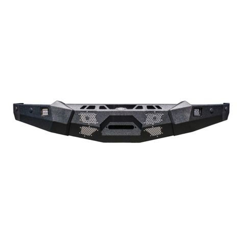
FRONT BUMPER WINCH & NON WINCH
TOOLS REQUIRED SKILL LEVEL TIME REQUIRED
- 13, 18, 21 & 22mm
- T30
- Push Pin Removal Tool
- Grinder or Sawzall
- Zip Ties
Before you install this kit — Read and understand all
instructions, warnings, cautions, and notes contained in
this installation instruction guide. Consult your vehicle
owner’s manual for proper disconnection of electrical and
lifting of vehicle if required for installation of this product.
This install may require some technical skills and
knowledge of basic mechanical work. If you do not feel that
you are capable of performing this install please take this
product to a trained professional.
After reading this guide please contact us with any
questions or concerns before installing product.
Customer Service: 855-680-9595
DV8 Offroad is not responsible for any bodily injury or harm to you
or your vehicle as a result of an improper install.
Proper installation of this kit required knowledge of the factory
recommended procedures for removal and installation of original
equipment components. We recommend that the factory shop manual
and any special tools needed to service your vehicle be on hand during
the installation. Installation of this kit without proper knowledge of the
factory recommended procedures may affect the performance of these
components and the safety of the vehicle
• Always wear eye protection when operating power tools
Inspect all contents of this package to make sure product is not damaged
and all installation hardware has been included. If parts are missing from
kit, please be prepared to provide the following information
1. Name of purchase location
2. Bar Code on side of box
3. Date above bar code
4. Date inside box cover
- Intermediate
- 2 people
Intermediate skill level required.
- 3.5 Hours
Time to install this should take
about 3.5 hours
WARNINGS/CAUTIONS BEFORE STARTING INSTALLATION
INSTALLATION MANUAL
855-680-9595
NEED HELP?
STEP 1
STEP 3
Begin by unpacking all items and
inspecting for missing pieces or
damage. If you have any concerns,
please contact the company the
product was purchased from.
To remove the bumper, using a 21mm
socket, remove the three mounting
nuts on each frame rail.
STEP 2
Begin by unplugging the bumper from
the main wire harness on the truck.
The plug can be found located on top
of the frame rail under the passenger
side headlight.
Note: If you have trouble removing this
plug, you can wait until the bumper has
been unbolted, however this will require
additional help to hold the bumper and
remove the plug.
(6) M14 x 35mm Bolts
(6) M14 Lock Nuts
(12) M14 Flat Washers
(6) M12 x 50mm Bolts
Hardware Included:
(6) M12 Nuts
(6) M12 Split Washers
(12) M12 Flat Washers
(4) Bumper Spacers
INSTALLATION MANUAL
855-680-9595
NEED HELP?
STEP 4
Once the nuts are removed, pull the
bumper off by leaning the center back
and pulling forward.
STEP 5
Once the bumper is off you will have
to remove two plugs still attached to
the bumper. One is directly under the
grille in the center, and the second is
on the passenger near the main plug
removed earlier. Unclip both plugs
to allow the bumper to be pulled
free. Set bumper on soft surface face
down.
INSTALLATION MANUAL
855-680-9595
NEED HELP?
STEP 6
Remove the shutter shroud by
removing the clips around the
outside.
STEP 7
Using a grinder or a Sawzall, safely
cut the crash bars on each side of the
frame. Ensure to paint any exposed
metal to prevent corrosion.
INSTALLATION MANUAL
855-680-9595
NEED HELP?
STEP 8
If your bumper is equipped from the
factory with front parking sensors,
begin by removing the automatic air
dampening system on the factory
bumper using a 13mm socket on the
three bolts located on each side.
STEP 9
Unplug the connector on each side of
the air dampening system and set off
to the side.
STEP 10
Using a T30 torx bit, remove the
four bolts holding fog light housing
on each side of the factory bumper.
Unplug the fog lights and set off to
the side.
NOTE: The bumper wire harness has a
mount on the fog light. Using your push
pin removal tool, remove the harness
from each light.
INSTALLATION MANUAL
855-680-9595
NEED HELP?
STEP 11
Using a 13mm socket, remove the four
bolts holing each bumper bracket.
STEP 12
If you have and adaptive cruise
control (ACC) module, unplug this off
the driver side bracket and set off to
the side since this will not be a part of
the bumper install.
NOTE: To relocate the ACC module, you
will need the FBFF1-BR. Use the FBBR1-BR
instructions for relocation steps before
you continue with remainder of bumper
install.
INSTALLATION MANUAL
855-680-9595
NEED HELP?
STEP 14
Using the push pin tool, remove the
harness from all points on the factory
bumper.
STEP 13
After you have full access to the
bumper wire harness, unclip each
sensor from the bracket by spreading
the side of the sensor bezels. Do not
overextend these tabs since they can
break.
INSTALLATION MANUAL
855-680-9595
NEED HELP?
STEP 17
Using a 22mm and 21mm socket,
install the wings onto the center
section using the supplied M14 bolts.
NOTE: If you do not have factory sensors,
use the provided sensor plugs and with
your setup, change to step 23.
STEP 16
Moving to the DV8 bumper, install the
supplied foam pads to the wings of
the bumper.
STEP 15
To remove the sensor bezels from the
bumper, squeeze the side of the bezel
from the back and pull the face from
the front.
INSTALLATION MANUAL
855-680-9595
NEED HELP?
STEP 20
Our bumper sensor holes are keyed to
t each sensor bezel into the correct
spot on the bumper. To install your
factory sensor bezels into the DV8
bumper, look for the letters marked
on each bezel. For example, this bezel
is marked “FIL” meaning “front inner
left”.
STEP 19
Once the sensors are in place, loosely
secure the wire into place with zip
ties (not provided) using the welded
in zip tie tabs.
STEP 18
Install the factory wire harness into
the bumper with the main plug lying
at the passenger side of the bumper.
Loosely lay the sensors over the
correlating holes. Different levels
of factory trims will offer different
amounts of sensors on the front
bumper. Utilize the holes on the
bumper that closely relate to the
factory bumper. Any remaining holes
will utilize the provided sensor plugs.
INSTALLATION MANUAL
855-680-9595
NEED HELP?
STEP 23
Install 3” pods into the wings using
hardware provided with the light.
NOTE: We are using two 3” DV8elite pod
lights for this install.
STEP 22
From the back, click each sensor into
the bezel while holding the face of
the bezel. Make sure both tabs on the
bezel are at against the sensor and
that the sensor is sitting ush in the
bezel.
STEP 21
After each bezel is matched up to the
correct location, you need to trim the
tabs on the bezel. Since our bumpers
use a thicker material, you will need
to either use snips or a small Dremel
to shave down the tabs. Take a little
material off and test t until tabs
click into place and bezel ts ush.
INSTALLATION MANUAL
855-680-9595
NEED HELP?
STEP 25
With help, lift the bumper over the
frame horns and using the provided
M12 hardware and a 18mm socket
and wrench, mount the bumper to the
factory bumper mounts. Leave loose
to allow for adjustment.
NOTE: We included some spacers with
the bumper. These are used to bring the
wings up closer to the body and can be
used based on your preference. If needed,
prior to install of the top two bolts on
each side, place up to two spacers on
each side prior to securing hardware.
STEP 24
If you are running the FBFF1-10 winch
version of this bumper, install your
winch now. Secure the wires away
from the back of the bumper to
ensure that they do not get in the way
during the bumper install.
INSTALLATION MANUAL
855-680-9595
NEED HELP?
STEP 28
To trim your inner fender, using snips
or a sharp razor blade, carefully cut
the inner fender. Make sure to leave
the mounting hole near the bumper
wing to the inner fender intact to
secure the inner fender.
STEP 27
Plug in center grille connector and
main bumper harness connector.
STEP 26
With help hold bumper into place
where you have even gaps all around
and tighten hardware down to 70 ft.
lbs.
INSTALLATION MANUAL
855-680-9595
NEED HELP?
STEP 29
Double check all hardware is
secure and wire fog lights to your
preference and wire your winch if
applicable.

Other DV8 OFFROAD Automobile Accessories manuals

DV8 OFFROAD SRGX-02 User manual

DV8 OFFROAD

DV8 OFFROAD SRGX-02 User manual

DV8 OFFROAD SPBR-05 User manual

DV8 OFFROAD

DV8 OFFROAD SPBR-05 User manual

DV8 OFFROAD DMT3-01 User manual

DV8 OFFROAD

DV8 OFFROAD DMT3-01 User manual

DV8 OFFROAD LBJL-11 User manual

DV8 OFFROAD

DV8 OFFROAD LBJL-11 User manual

DV8 OFFROAD D-JP-190024-BLK User manual

DV8 OFFROAD

DV8 OFFROAD D-JP-190024-BLK User manual

DV8 OFFROAD FDBR-01 User manual

DV8 OFFROAD

DV8 OFFROAD FDBR-01 User manual

DV8 OFFROAD FDGL-06 User manual

DV8 OFFROAD

DV8 OFFROAD FDGL-06 User manual

DV8 OFFROAD LPBM-03 User manual

DV8 OFFROAD

DV8 OFFROAD LPBM-03 User manual

DV8 OFFROAD MPJL-01 User manual

DV8 OFFROAD

DV8 OFFROAD MPJL-01 User manual

DV8 OFFROAD D-JP-180011-BK User manual

DV8 OFFROAD

DV8 OFFROAD D-JP-180011-BK User manual

DV8 OFFROAD D-JL-180014-SIL4 User manual

DV8 OFFROAD

DV8 OFFROAD D-JL-180014-SIL4 User manual

DV8 OFFROAD CCBR-01 User manual

DV8 OFFROAD

DV8 OFFROAD CCBR-01 User manual

DV8 OFFROAD RRJK-03 User manual

DV8 OFFROAD

DV8 OFFROAD RRJK-03 User manual

DV8 OFFROAD FDJL-07 User manual

DV8 OFFROAD

DV8 OFFROAD FDJL-07 User manual

DV8 OFFROAD MPGX-02 User manual

DV8 OFFROAD

DV8 OFFROAD MPGX-02 User manual

DV8 OFFROAD SPEC Series User manual

DV8 OFFROAD

DV8 OFFROAD SPEC Series User manual

DV8 OFFROAD LPBR-04 User manual

DV8 OFFROAD

DV8 OFFROAD LPBR-04 User manual

DV8 OFFROAD FS-15 Series User manual

DV8 OFFROAD

DV8 OFFROAD FS-15 Series User manual

DV8 OFFROAD RBJL-12 User manual

DV8 OFFROAD

DV8 OFFROAD RBJL-12 User manual

DV8 OFFROAD SRBR-06 User manual

DV8 OFFROAD

DV8 OFFROAD SRBR-06 User manual

DV8 OFFROAD CCJL-01 User manual

DV8 OFFROAD

DV8 OFFROAD CCJL-01 User manual

DV8 OFFROAD SPEC Series User manual

DV8 OFFROAD

DV8 OFFROAD SPEC Series User manual

DV8 OFFROAD MPT3-01 User manual

DV8 OFFROAD

DV8 OFFROAD MPT3-01 User manual

DV8 OFFROAD SRJK-08 User manual

DV8 OFFROAD

DV8 OFFROAD SRJK-08 User manual

Popular Automobile Accessories manuals by other brands

Atera STRADA SPORT M quick start guide

Atera

Atera STRADA SPORT M quick start guide

Rear view safety RVS-OP7 user manual

Rear view safety

Rear view safety RVS-OP7 user manual

Directed Electronics PYTHON 872 user manual

Directed Electronics

Directed Electronics PYTHON 872 user manual

Toyota PZ403-9963F-00 Fitting instructions

Toyota

Toyota PZ403-9963F-00 Fitting instructions

Whispbar K089 Fitting Instructions for Basic Carrier

Whispbar

Whispbar K089 Fitting Instructions for Basic Carrier

DFI VP101-BT user manual

DFI

DFI VP101-BT user manual

Hama 00 123530 operating instructions

Hama

Hama 00 123530 operating instructions

Mazda 0000 8C Z01 installation instructions

Mazda

Mazda 0000 8C Z01 installation instructions

STO N SHO SNS 280 Installation procedures

STO N SHO

STO N SHO SNS 280 Installation procedures

Bazooka UT6200 troubleshooting guide

Bazooka

Bazooka UT6200 troubleshooting guide

curt 55513 installation instructions

curt

curt 55513 installation instructions

PAC TATO manual

PAC

PAC TATO manual

travall TDG 1634 Fitting instructions

travall

travall TDG 1634 Fitting instructions

DU-HA 70827 manual

DU-HA

DU-HA 70827 manual

Douglas Dynamics Fisher Minute Mount 2 XLS 50600 installation instructions

Douglas Dynamics

Douglas Dynamics Fisher Minute Mount 2 XLS 50600 installation instructions

Flash Cover MN003 installation manual

Flash Cover

Flash Cover MN003 installation manual

Cruz Evo Rack Pro P32-158 Assembly instructions

Cruz

Cruz Evo Rack Pro P32-158 Assembly instructions

Kuda 286340 Installation instruction

Kuda

Kuda 286340 Installation instruction

manuals.online logo
manuals.online logoBrands
  • About & Mission
  • Contact us
  • Privacy Policy
  • Terms and Conditions

Copyright 2025 Manuals.Online. All Rights Reserved.