manuals.online logo
Brands
  1. Home
  2. •
  3. Brands
  4. •
  5. DV8 OFFROAD
  6. •
  7. Automobile Accessories
  8. •
  9. DV8 OFFROAD FDJK-07 User manual

DV8 OFFROAD FDJK-07 User manual

6400 SYCAMORE CANYON BLVD.
RIVERSIDE, CALIFORNIA 92507
855-680-9595
WWW.DV8OFFROAD.COM
PRODUCT
INSTALLATION MANUAL
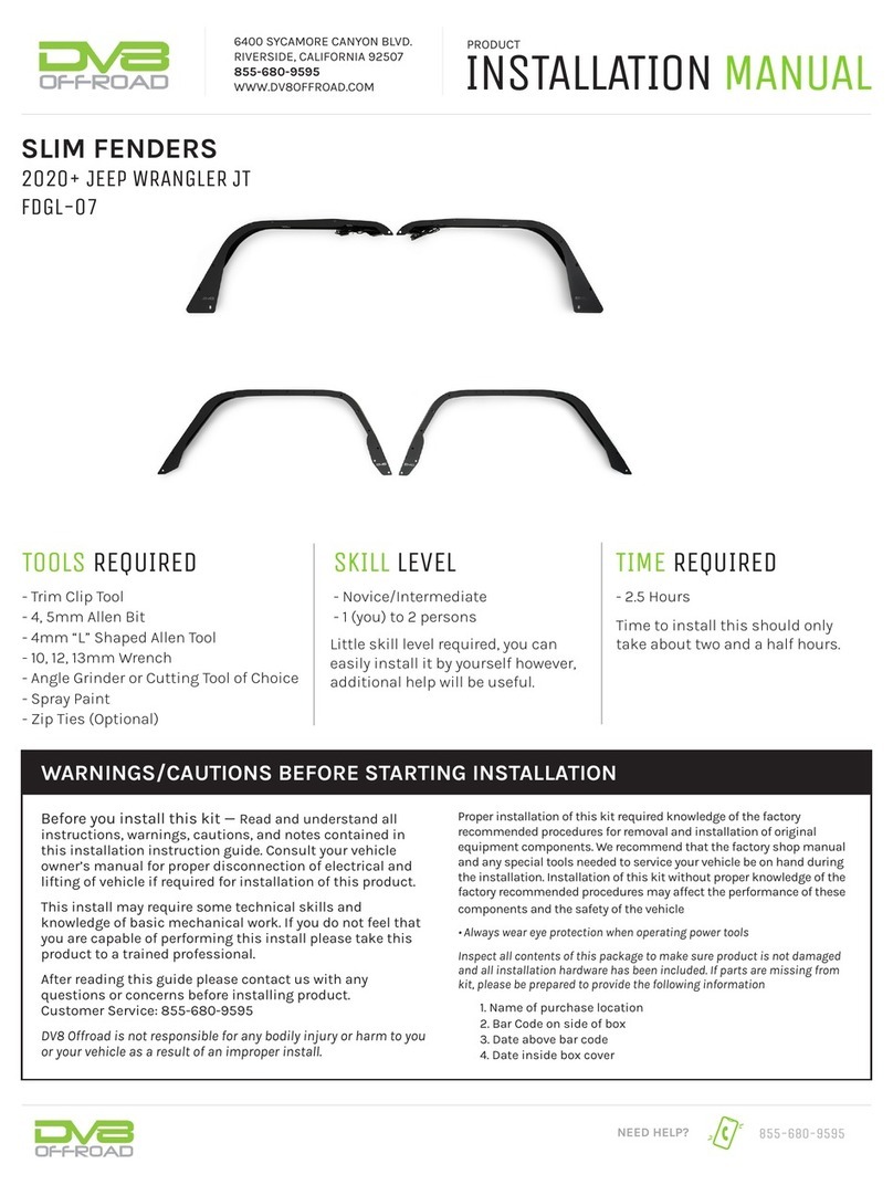
SLIM FENDERS
07-18 JEEP WRANGLER JK
FDJK-07
TOOLS REQUIRED
SKILL LEVEL TIME REQUIRED
- Trim Clip Tool
- 10mm Socket
- #4 Allen Bit
- 13mm Wrench
- Scissors or Blade
- Metal Cutting Tool, Painters Tape, Color
Matched or Black Paint (Optional)
- Nutsert tool, Power Ratchet, Low Prole
Ball End #4 Allen Key (Optional, Highly
Recommended)
- Zip Ties
Before you install this kit — Read and understand all
instructions, warnings, cautions, and notes contained in
this installation instruction guide. Consult your vehicle
owner’s manual for proper disconnection of electrical and
lifting of vehicle if required for installation of this product.
This install may require some technical skills and
knowledge of basic mechanical work. If you do not feel that
you are capable of performing this install please take this
product to a trained professional.
After reading this guide please contact us with any
questions or concerns before installing product.
Customer Service: 855-680-9595
DV8 Offroad is not responsible for any bodily injury or harm to you
or your vehicle as a result of an improper install.
Proper installation of this kit required knowledge of the factory
recommended procedures for removal and installation of original
equipment components. We recommend that the factory shop manual
and any special tools needed to service your vehicle be on hand during
the installation. Installation of this kit without proper knowledge of the
factory recommended procedures may affect the performance of these
components and the safety of the vehicle
• Always wear eye protection when operating power tools
Inspect all contents of this package to make sure product is not damaged
and all installation hardware has been included. If parts are missing from
kit, please be prepared to provide the following information
1. Name of purchase location
2. Bar Code on side of box
3. Date above bar code
4. Date inside box cover
- Novice/Intermediate
- 1 (you) to 2 persons
Little skill level required, you can
easily install it by yourself however,
additional help will be useful.
- 2.5 Hours
Time to install this should only
take about two and a half hours.
WARNINGS/CAUTIONS BEFORE STARTING INSTALLATION
855-680-9595
NEED HELP?
INSTALLATION MANUAL
NEED HELP? 855-680-9595
STEP 1 | If you installing the DV8 JK
Front Inner Fenders, retain the factory
hardware during uninstall, some if it may
be re-used during installation of the inner
fenders.
It is recommended to install the inner
fenders after the outer fenders, so there is
easier access route and secure any wiring.
Disconnect the side marker light wiring
harness by pressing the release clip and
pulling. Do not confuse this with the turn
signal connector.
Use a trim clip tool if necessary.
FENDER UNINSTALL
INSTALLATION MANUAL
NEED HELP? 855-680-9595
STEP 2 | Use a 10mm socket to
remove the hardware securing the fenders
to the vehicle.
There are ve fasteners located along the
top of each fender and one more securing
the fenders to the support brackets.
INSTALLATION MANUAL
NEED HELP? 855-680-9595
STEP 3 | Use a trim clip tool to
remove the ve trim clips located along
the interior of each fender.
INSTALLATION MANUAL
NEED HELP? 855-680-9595
STEP 4 | Remove the fender are by
pulling rmly away and up from the tire to
remove it from the plastic clips.
If you pull away from the body of the
vehicle, the plastic clips may break.
The clips are pictured at the bottom of the
page.
Note how the fasteners follow the curve
of the fender and how you will adjust the
direction of the pull as you move from the
side to the upper part of the fender.
Be careful not to scratch the vehicle when
removing the fenders.
INSTALLATION MANUAL
NEED HELP? 855-680-9595
STEP 5 | Use a trim clip tool to
remove all the plastic fasteners from the
front fender mounts.
STEP 6 | Use a trim clip tool to
remove the ve trim clips located along
the interior of each rear inner fender.
INSTALLATION MANUAL
NEED HELP? 855-680-9595
STEP 7 | With the trim clips removed,
un-install the fender are by pulling
directly away and up from the tire to
remove it from the plastic clips.
If you pull away from the body of the
vehicle, the plastic clips may break.
The fasteners follow the curve of the
fender similar to the front.
Starting at the front of the fender. Pull
rmly away from the tire toward the front
of the vehicle and up to unclip the fender
from the fasteners.
As you move towards the middle, begin to
pull straight up away from the tire.
Once at the rear of the fender, pull away
from the tire towards the rear of the
vehicle, and up.
Be careful not to scratch the vehicle when
removing the fenders.
INSTALLATION MANUAL
NEED HELP? 855-680-9595
STEP 8 | Remove all remaining
plastic fasteners from each rear fender
using a trim clip tool.
INSTALLATION MANUAL
NEED HELP? 855-680-9595
STEP 9 | Install the gaskets onto the
fenders.
The gaskets are notched to line up with
the mounting holes on each fender. Match
each gasket with the corresponding
fender.
Peel the back the plastic cover to reveal
the adhesive and install the gaskets onto
each fender.
Begin by unpacking all items and inspecting
for missing pieces or damage. If you have any
concerns, please contact the company the
product was purchased from. Extra hardware
may be included with the product.
(30) M6x20 Allen
(2) M6x20 Hex
(32) M6 Flat Washers
(20) M6 Serrated Nuts
(32) M6x14 Nutserts
(4) Rubber Gasket Seals
(1) Nutsert Tool Kit
HARDWARE INCLUDED
INSTALLATION MANUAL
NEED HELP? 855-680-9595
STEP 10 | Trimanyexcessgasketfrom
each end of all fenders using scissors or
a blade.
Carefully remove any excess tape that
from all mounting holes that may
obstruct hardware during install.
STEP 11 | Hold up the fenders to the
vehicle and note what holes will be used.
Install the provided nutserts using a
nutsert tool. If you do not own a nutsert
tool, we provide one with our kit.
For instructions on how to use the nutsert
tool, scroll to the last page.
Tip: Hold up the fender the vehicle as a guide to
determine which holes require a nutsert.
INSTALLATION MANUAL
NEED HELP? 855-680-9595
STEP 12 | (Optional) Cut the front
fender mounts off and grind it down
so it is ush with the vehicle. Paint
is recommended on the bare steel to
prevent rust.
While this step is not 100% necessary for
tment, we recommend doing this step to
achieve the best look possible.
STEP 13 | Loosely install the front
fenders using the provided M6 hardware.
Check that the gasket does not move out
of place during install.
There are two hex bolts included to be
used in the rear corners of the front
fenders for easier access.
INSTALLATION MANUAL
NEED HELP? 855-680-9595
STEP 14 | Use a #4 allen bit and 10mm
wrench to secure all hardware on the front
fenders.
STEP 15 | Pull the rubber grommet off
the light and slide it through to mounting
hole.
Then pull the grommet through the hole
until it is evenly seated in the hole.
INSTALLATION MANUAL
NEED HELP? 855-680-9595
STEP 16 | Pressthelightgentlyuntilit
seated securely in the grommet.
STEP 17 | Connect the light to the
factory connector and secure it out of the
way using a zip ties.
We use a pre-existing hole in the body
directly behind the grille and below the
front of the fender.
INSTALLATION MANUAL
NEED HELP? 855-680-9595
STEP 18 | Hold up the fenders to
the vehicle and note what holes will be
used. Install the provided nutserts using
a nutsert tool. If you do not own a nutsert
tool, we provide one with our kit.
For instructions on how to use the nutsert
tool, scroll to the last page.
Tip: Hold up the fender the vehicle as a guide to
determine which holes require a nutsert.
STEP 19 | Loosely secure the fenders
to the vehicle using the provided M6
hardware. Check that the gasket does not
move out of place during install.
Start at the rear of the fender/vehicle and
move forward, installing the hardware in
these three locations last.
Due to the angle of the mounting,
these mounting holes have the most
adjustment, and so it is easiest to do
them last.
INSTALLATION MANUAL
NEED HELP? 855-680-9595
STEP 20 | Use a #4 allen bit to secure
the all hardware on the rear fenders.
Check the gasket on all fenders and use
a trim clip tool to press any area of the
gasket that may have slipped out slightly
during install.
INSTALLATION MANUAL
NEED HELP? 855-680-9595
STEP 21 | To use the nutsert tool,
slider the M6 washer and spacer onto the
provided M6x50 bolt.
Then install a nutsert onto the exposed
threads by hand.
STEP 22 | Slide the nutsert tool with
the nutsert into the mounting hole.
Ensure the ange of the nutsert is at
against the vehicle prior to tightening.
STEP 23 | Use a 12mm wrench to hold
the spacer while tightening with a 10mm
socket. Tighten slowly until the nutsert is
set properly. Do not over tighten.
Nutsert should be “crushed” against the
inside of the fender so that it is tight and
secure.
When nished remove the nutsert tool
using a 10mm socket and repeat as
needed.
Note: Be sure to hold the spacer tight so it does
not move and scratch paint.

Other DV8 OFFROAD Automobile Accessories manuals

DV8 OFFROAD ABJL-01 User manual

DV8 OFFROAD

DV8 OFFROAD ABJL-01 User manual

DV8 OFFROAD SPEC Series User manual

DV8 OFFROAD

DV8 OFFROAD SPEC Series User manual

DV8 OFFROAD STJL-05 User manual

DV8 OFFROAD

DV8 OFFROAD STJL-05 User manual

DV8 OFFROAD DMT3-01 User manual

DV8 OFFROAD

DV8 OFFROAD DMT3-01 User manual

DV8 OFFROAD SPBR-01 User manual

DV8 OFFROAD

DV8 OFFROAD SPBR-01 User manual

DV8 OFFROAD TSJL-03 User manual

DV8 OFFROAD

DV8 OFFROAD TSJL-03 User manual

DV8 OFFROAD FDBR-01 User manual

DV8 OFFROAD

DV8 OFFROAD FDBR-01 User manual

DV8 OFFROAD CCJL-01 User manual

DV8 OFFROAD

DV8 OFFROAD CCJL-01 User manual

DV8 OFFROAD SPEC Series User manual

DV8 OFFROAD

DV8 OFFROAD SPEC Series User manual

DV8 OFFROAD FDJL-07 User manual

DV8 OFFROAD

DV8 OFFROAD FDJL-07 User manual

DV8 OFFROAD SRBR-03 User manual

DV8 OFFROAD

DV8 OFFROAD SRBR-03 User manual

DV8 OFFROAD FDGL-06 User manual

DV8 OFFROAD

DV8 OFFROAD FDGL-06 User manual

DV8 OFFROAD CCT2-01 User manual

DV8 OFFROAD

DV8 OFFROAD CCT2-01 User manual

DV8 OFFROAD RBJL-11 User manual

DV8 OFFROAD

DV8 OFFROAD RBJL-11 User manual

DV8 OFFROAD LPBM-03 User manual

DV8 OFFROAD

DV8 OFFROAD LPBM-03 User manual

DV8 OFFROAD D-JP-180014-STR4 User manual

DV8 OFFROAD

DV8 OFFROAD D-JP-180014-STR4 User manual

DV8 OFFROAD MTO Series User manual

DV8 OFFROAD

DV8 OFFROAD MTO Series User manual

DV8 OFFROAD RRJK-03 User manual

DV8 OFFROAD

DV8 OFFROAD RRJK-03 User manual

DV8 OFFROAD D-JP-190024-BLK User manual

DV8 OFFROAD

DV8 OFFROAD D-JP-190024-BLK User manual

DV8 OFFROAD RRUN-02 User manual

DV8 OFFROAD

DV8 OFFROAD RRUN-02 User manual

DV8 OFFROAD RRUN-03 User manual

DV8 OFFROAD

DV8 OFFROAD RRUN-03 User manual

DV8 OFFROAD RBJL-12 User manual

DV8 OFFROAD

DV8 OFFROAD RBJL-12 User manual

DV8 OFFROAD D-JL-180014-SIL4 User manual

DV8 OFFROAD

DV8 OFFROAD D-JL-180014-SIL4 User manual

DV8 OFFROAD OE PLUS SRBR-05 User manual

DV8 OFFROAD

DV8 OFFROAD OE PLUS SRBR-05 User manual

Popular Automobile Accessories manuals by other brands

HHO Plus CCPWM60A installation manual

HHO Plus

HHO Plus CCPWM60A installation manual

Metra Electronics 99-9100 installation instructions

Metra Electronics

Metra Electronics 99-9100 installation instructions

Big Country Pull Pro installation instructions

Big Country

Big Country Pull Pro installation instructions

Thule Rapid Fixpoint XT 3005 Fitting instructions

Thule

Thule Rapid Fixpoint XT 3005 Fitting instructions

Dynojet Power commander V installation instructions

Dynojet

Dynojet Power commander V installation instructions

Aim GT 320-350 user guide

Aim

Aim GT 320-350 user guide

Fjordsen Bolt set Assembly manual

Fjordsen

Fjordsen Bolt set Assembly manual

Thule Rapid System 1362 Fitting instructions

Thule

Thule Rapid System 1362 Fitting instructions

Cequent Draw-Tite 76026 installation instructions

Cequent

Cequent Draw-Tite 76026 installation instructions

Warn 103950 quick start guide

Warn

Warn 103950 quick start guide

Jushengtimes 323 user manual

Jushengtimes

Jushengtimes 323 user manual

Mont Blanc FK 45 Fitting instructions

Mont Blanc

Mont Blanc FK 45 Fitting instructions

Clarion SIRIUS SIRCR installation guide

Clarion

Clarion SIRIUS SIRCR installation guide

Yada BT54860 user manual

Yada

Yada BT54860 user manual

Directed Directechs DB3 installation guide

Directed

Directed Directechs DB3 installation guide

DRAGONFIRE 04-0820 quick start guide

DRAGONFIRE

DRAGONFIRE 04-0820 quick start guide

SimPark Easymatic-E installation manual

SimPark

SimPark Easymatic-E installation manual

bosal 035-898 Fitting instructions

bosal

bosal 035-898 Fitting instructions

manuals.online logo
manuals.online logoBrands
  • About & Mission
  • Contact us
  • Privacy Policy
  • Terms and Conditions

Copyright 2025 Manuals.Online. All Rights Reserved.