manuals.online logo
Brands
  1. Home
  2. •
  3. Brands
  4. •
  5. Dynojet
  6. •
  7. Automobile Accessories
  8. •
  9. Dynojet Power commander V User manual

Dynojet Power commander V User manual

14-007 www.powercommander.com 2009 Ducati Desmosedici - PCV - 1
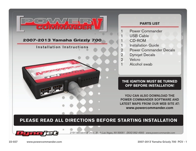
PARTS LIST
1 Power Commander
1 USB Cable
1 Installation Guide
2 Power Commander Decals
2 Dynojet Decals
2 Velcro strips
1 Alcohol swab
2 Zip ties
2 Posi-taps
THE LATEST POWER COMMANDER
SOFTWARE AND MAP FILES CAN BE
DOWNLOADED FROM OUR WEB SITE AT:
www.powercommander.com
2009 Ducati Desmosedici
Installation Instructions
PLEASE READ ALL DIRECTIONS BEFORE STARTING INSTALLATION
THE IGNITION MUST BE TURNED
OFF BEFORE INSTALLATION!
2191 Mendenhall Drive North Las Vegas, NV 89081 (800) 992-4993 www.powercommander.com
14-007 www.powercommander.com 2009 Ducati Desmosedici - PCV - 2
EXPANSION PORTS 1 & 2
Optional Accessories such as
POD-300 unit or Auto-tune kit.
POWER COMMANDER V
INPUT ACCESSORY GUIDE
Map - (Input 1 or 2) The PCV has the ability to hold
2 different base maps. You can switch on the
fly between these two base maps when you
hook up a switch to the MAP inputs. You can
use any open/close type switch. The polarity
of the wires is not important. When using the
Autotune kit one position will hold a base map
and the other position will let you activate the
learning mode. When the switch is “CLOSED”
Autotune will be activated. (Set to Switch
Input #1 by default.)
Shifter- (Input 1 or 2) These inputs are for use with the
Dynojet quickshifter. Insert the wires from the
Dynojet quickshifter into the SHIFTER inputs.
The polarity of the wires is not important. (Set
to Switch Input #2 by default.)
Speed- If your application has a speed sensor then
you can tap into the signal side of the sensor
and run a wire into this input. This will allow
you to calculate gear position in the Control
Center Software. Once gear position is setup
you can alter your map based on gear position
and setup gear dependent kill times when
using a quickshifter.
Analog- This input is for a 0-5v signal such as
engine temp, boost, etc. Once this input
is established you can alter your fuel curve
based on this input in the control center
software.
Crank- Do NOT connect anything to this port unless
instructed to do so by Dynojet. It is used to
transfer crank trigger data from one module to
another.
ACCESSORY INPUTS
Wire connections:
To input wires into the PCV first remove the rubber
plug on the backside of the unit and loosen the
screw for the corresponding input. Using a 22-24
gauge wire strip about 10mm from its end. Push the
wire into the hole of the PCV until is stops and then
tighten the screw. Make sure to reinstall the rubber
plug.
NOTE: If you tin the wires with solder it will make
inserting them easier.
CRANK
ANALOG
SPEED
INPUT 1 (Grnd)
INPUT 1
INPUT 2 (Grnd)
INPUT 2
USB CONNECTION
14-007 www.powercommander.com 2009 Ducati Desmosedici - PCV - 3
1 Remove the seat and fuel tank.
2 Remove the left side fairing.
3 Mount the PCV to left side inner panel, using the supplied Velcro (Fig. A).
Make sure to use the alcohol swab to clean both surfaces before attaching the
Velcro.
4 Locate the throttle body sub-connector on the left side of the air box (Fig. B).
Unplug this connector by turning counter-clockwise.
5 Plug the PCV wiring harness in-line of the stock wiring harness and throttle
body sub-harness (Fig. C).
FIG.A
FIG.C
Remove
Ground wire
FIG.B
Stk connector
PCV connector
Unplug
PCV connector
14-007 www.powercommander.com 2009 Ducati Desmosedici - PCV - 4
6 Locate the Throttle Position Sensor connector on
the left side of the throttle bodies. This is a 3-pin
connector located to the inside of the frame.
Unplug this connector from the throttle bodies to gain
access to the wires.
7 Using one of the supplied Posi-taps attach the GREY
wire from the PCV to the stock ORANGE wire of the
TPS harness (Fig. D).
8 Using the other supplied Posi-tap, attach the BLACK/
WHITE wire from the PCV to the stock PURPLE/
BLACK wire of the stock TPS connector (Fig. D).
FIG.D
9 Plug the stock TPS connector back onto the throttle bodies.
10 Route the PCV harness along the left side of the engine and go towards the
battery (Fig. E).
11 Use the supplied zip ties to secure the PCV harness to the main wiring
harness.
FIG.E
12 Route the PCV ground wire along the stock ground wire and secure it to the
negative (-) terminal of the bike’s battery (Fig. F).
13 Reinstall the bodywork, the seat, and the fuel tank.
FIG.F
PCV harness
PCV ground

Other manuals for Power commander V

95

Other Dynojet Automobile Accessories manuals
Dynojet POWER VISION PV3-2509C User manual

Dynojet

Dynojet POWER VISION PV3-2509C User manual

Dynojet Power Commander III USB User manual

Dynojet

Dynojet Power Commander III USB User manual

Dynojet POWER VISION 3 User manual

Dynojet

Dynojet POWER VISION 3 User manual

Dynojet power commander III User manual

Dynojet

Dynojet power commander III User manual

Dynojet Power Commander III User manual

Dynojet

Dynojet Power Commander III User manual

Dynojet power commander III User manual

Dynojet

Dynojet power commander III User manual

Dynojet Power commander V User manual

Dynojet

Dynojet Power commander V User manual

Dynojet POWER VISION PV3-25-09 User manual

Dynojet

Dynojet POWER VISION PV3-25-09 User manual

Dynojet Power commander V User manual

Dynojet

Dynojet Power commander V User manual

Dynojet POWER COMMANDER III USB EX User manual

Dynojet

Dynojet POWER COMMANDER III USB EX User manual

Dynojet POWER VISION PV3-2511C User manual

Dynojet

Dynojet POWER VISION PV3-2511C User manual

Dynojet Power commander V User manual

Dynojet

Dynojet Power commander V User manual

Dynojet Power Commander III User manual

Dynojet

Dynojet Power Commander III User manual

Dynojet POWER VISION PV3-25-04 User manual

Dynojet

Dynojet POWER VISION PV3-25-04 User manual

Dynojet Power commander V User manual

Dynojet

Dynojet Power commander V User manual

Dynojet Power commander V User manual

Dynojet

Dynojet Power commander V User manual

Dynojet WIDEBAND CX User manual

Dynojet

Dynojet WIDEBAND CX User manual

Dynojet POWER VISION PV3-25-08 User manual

Dynojet

Dynojet POWER VISION PV3-25-08 User manual

Dynojet POWER VISION PV3-2504C User manual

Dynojet

Dynojet POWER VISION PV3-2504C User manual

Dynojet Power Commander V 22-027 User manual

Dynojet

Dynojet Power Commander V 22-027 User manual

Dynojet Power commander V User manual

Dynojet

Dynojet Power commander V User manual

Dynojet Power commander V User manual

Dynojet

Dynojet Power commander V User manual

Dynojet POWER VISION PV3-17-02 User manual
Dynojet

Dynojet POWER VISION PV3-17-02 User manual

Dynojet Power commander V Service manual
Dynojet

Dynojet Power commander V Service manual

Popular Automobile Accessories manuals by other brands

Graco Compact Dyna-Star 132662 installation instructions

Graco

Graco Compact Dyna-Star 132662 installation instructions

Airxcel Aqua-Hot GEN1 Series Use and care guide

Airxcel

Airxcel Aqua-Hot GEN1 Series Use and care guide

packright rightline GEAR StrapRight Strap Set quick start guide

packright

packright rightline GEAR StrapRight Strap Set quick start guide

Havis-Shields Impala C-TCB-22 brochure

Havis-Shields

Havis-Shields Impala C-TCB-22 brochure

APS iBoard IB-R296 quick start guide

APS

APS iBoard IB-R296 quick start guide

Fortin EVO ONE THAR-GM7 Installation

Fortin

Fortin EVO ONE THAR-GM7 Installation

iSimple Media Gateway ISGM11 PGHGM1 owner's manual

iSimple

iSimple Media Gateway ISGM11 PGHGM1 owner's manual

Mont Blanc FK199 Fitting instructions

Mont Blanc

Mont Blanc FK199 Fitting instructions

AL-KO AKS 1300 operating instructions

AL-KO

AL-KO AKS 1300 operating instructions

Camos RV-566 instruction manual

Camos

Camos RV-566 instruction manual

Steinhof R-104 FITTING AND OPERATION MANUAL

Steinhof

Steinhof R-104 FITTING AND OPERATION MANUAL

Thule Kit 1003 Fitting instructions

Thule

Thule Kit 1003 Fitting instructions

Ground Zero GZTC 1.0FX owner's manual

Ground Zero

Ground Zero GZTC 1.0FX owner's manual

Polaris 2883687 instructions

Polaris

Polaris 2883687 instructions

ARB Airlocker RD146 installation guide

ARB

ARB Airlocker RD146 installation guide

Marquardt B8N user manual

Marquardt

Marquardt B8N user manual

Brink 727617 installation instructions

Brink

Brink 727617 installation instructions

Memphis CANAMX365FE quick start guide

Memphis

Memphis CANAMX365FE quick start guide

manuals.online logo
manuals.online logoBrands
  • About & Mission
  • Contact us
  • Privacy Policy
  • Terms and Conditions

Copyright 2025 Manuals.Online. All Rights Reserved.