manuals.online logo
Brands
  1. Home
  2. •
  3. Brands
  4. •
  5. Dynojet
  6. •
  7. Motorcycle Accessories
  8. •
  9. Dynojet 4-126 User manual

Dynojet 4-126 User manual

Quickshifter Installation Guide - 1
2191 Mendenhall Drive North Las Vegas, NV 89081
1-800-992-4993 www.dynojet.com
4-126
Installation Instructions
PARTS LIST
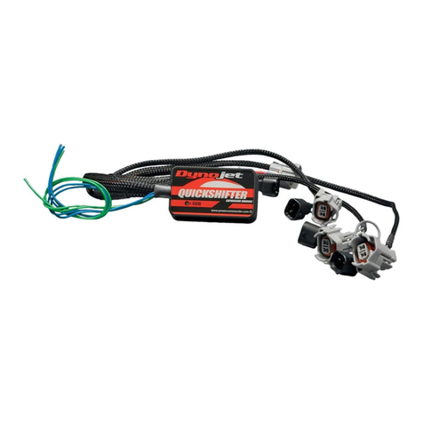
1 Quickshifter Stand Alone
1 Installation Guide
2 Dynojet Decal
2 Cable Tie
2 Velcro
1 Alcohol Swab
PLEASE READ ALL DIRECTIONS BEFORE STARTING INSTALLATION
Read this instruction manual before fitting and operating your product
PRECAUTIONS:
When installing this product it is advisable to position the motorcycle/vehicle so
it cannot cause injury or damage by falling over/rolling forwards or backwards.
The use of a paddock stand is ideal or if necessary chock the wheels.
Ensure that the ignition supply is switched off at all times unless instructed
otherwise within this manual.
When removing or adding electrical cables to the vehicle battery or wiring
harness always remove the negative earth cable/terminal before the positive
cable/terminal. Replace the negative earth cable/terminal last to avoid
shorting the electrical system.
When mounting the components ensure that the units are protected from
excessive vibration and the environmental elements, and that they are securely
mounted.
Be careful not to bend or pull the wires exiting the module as this could
compromise the weather proofing causing water to enter the module.
When routing electrical cables ensure the cables cannot become trapped or
pinched which could result in malfunction and secure with cable ties where
necessary.
TROUBLESHOOTING
1. No power-up - Check for incorrect battery terminal connections, blown
fuses, poor negative battery terminal connections. Check for severed or trapped
wires.
2. No quickshifter interrupt - Check the Quickshifter is being operated above
approximatley 3000RPM. Check for correct connection of the Quickshifter
harness connectors with the yellow dots and their associated grey link wire
alignment. Verify the Quickshifter sensor output. Check for severed or trapped
wires. Check that the Quickshifter harness connectors have not been greased
as this will cause a poor electrical connection!
3. Engine misfire - Verify the control unit mounting position and check
for isolation from vibration. Check plug and play connections. Verify ignition
coil type and suitability and correct connection of the Quickshifter harness
connectors with the yellow dots and their associated grey link wire alignment.
Verify the Quickshifter sensor output.
4. For further troubleshooting contact Dynojet.
4-126 www.dynojet.com Quickshifter Installation Guide - 2
Fitting the Control Unit
The Ignition Quickshifter control unit should be positioned so it does not exceed
an operating temperature of 160°F and must be installed where it is protected
from excessive vibration and harsh environmental elements. Under the seat area or
passenger seat is an ideal position.
1 Locate a suitable flat surface for the control unit to adhere to.
Note: Do not actually fix the control unit into position until you have installed the
rest of the components and have routed the relevant cables.
2 Once you have completed the rest of the installation you can then finally fix the
control unit into position using the supplied Velcro mounting pads.
Make sure you de-grease and warm up the mounting surfaces prior to peeling
the backing off of the Velcro pads and securing into position. Cold surfaces
result in poor adhesion.
No part of the Ignition Quickshifter housing is permitted to touch any
other object such as the chassis, bodywork, etc.
Connecting the Quickshifter Harness
If your vehicle has stick coils they could be either Denso or Mitsubishi type. These
ignition coils may require you to remove the blue and white wires along with the grey
link wire in the Quickshifter harness connector #1 and swap the wire positions in the
connectors as shown, refer to Figure 1. This enables the Ignition Quickshifter to obtain
12v from the stock harness.
Note: The RED wire and GREY link wire in the Quickshifter harness connector #1
must align with the +12Volt supply wire in the OEM ignition coil connector. Only
the BLUE and WHITE wired connector needs to have the wires swapped and the
GREY link wire aligned as shown. It is crucial that if you need to swap the wires
that you swap both the male AND female connector.
We have found that most Kawasaki and Yamaha models need to be swapped.
Typically there will be two wires in each OEM ignition coil connector. The wire which
is the same color in each OEM ignition coil connector will be the +12Volt supply wire.
In the example shown in Figure 1, the +12Volt wire is PURPLE although it might be a
different color with each installation. You can double check this by using a digital volt
meter.
If your vehicle does not feature these particular ignition stick coils see Figure 2.
Figure 1: OEM Ignition Coil Connector Harness
To swap the wires in the white
and black connectors with the
yellow dots gently lift the tabs
up then pull the wires out from
the back of the connector. Then
re-insert the wires as required
RIGHT! IGNITION
COIL WIRES ARE
WIRED CORRECTLY
WRONG! IGNITION
COIL WIRES ARE
CROSSED OVER
AND MISALIGNED
WRONG! ALL
IGNITION COIL
WIRES ARE
MISALIGNED
1. Route the harness through the motorcycle/vehicle so the WHITE and BLACK
Quickshifter connectors end up in close proximity to the ignition coils. Do not run
the Quickshifter harness next to the OEM vehicle harness. One at a time unplug the
original connector on each ignition coil and connect one male and female Quickshifter
harness connector to the ignition coil and its original connector. You will need to do
this on each of the ignition coils.
2. Connect the black eyelet ring terminal wire to the negative battery terminal only.
3. Plug the quickshifter sensor into the 2 pin, GREY connector of the Intellishift
Quickshifter harness.
If you are using this on a 3 cylinder model do not use the YELLOW and GREY colored
leads.
4-126 www.dynojet.com Quickshifter Installation Guide - 3
Figure 2: Splicing into the OEM harness
PRO-TUNER Mode Adjustments
It should not be necessary to enter Pro-Tuner-Mode unless you wish to experiment with the
FACTORY DEFAULT SETTINGS. It may be possible to improve the `feel’ of the Intellishift Quick-
shifter System by incrementing and decrementing the BASE SETTINGS to suit a particular rider
or vehicle transmission.
To enter `Pro-Tuner-Mode’ switch on the ignition and then within the first 20 seconds move the
gear lever into a `trigger’ position where the status LED illuminates solid GREEN and hold in this
position for 6 seconds until the GREEN status LED changes to RED then when you release the
gear lever the status LED will change to flashing ORANGE to indicate you have entered
`Pro-Tuner-Mode’. You can now release the gear lever.
NOTE1: The `primary’ default interrupt duration is 66ms in each RPM band.
NOTE2: The status LED will flash ORANGE in the sensor trigger force section.
NOTE3: The status LED will flash GREEN to indicate what RPM band you are about to adjust,
There are 5 bands, 1 flash equals RPM Band #1, 2 flashes equals RPM Band #2 and so on.
NOTE4: The status LED will flash RED in each of the RPM bands to indicate the interrupt
duration, each flash will increase or decrease the interrupt duration by 2ms (milliseconds).
Pro-Tuner-Mode tutorial
Go ahead and enter Pro-Tuner-Mode, the status LED will be flashing ORANGE 5 times (default
setting) The feel of the sensor trigger force point is a personal thing to the rider. If you would like
to feel a little more force on the gear lever before the quickshift happens you can increase the
sensor trigger force by following example 1.
To save the sensor trigger force setting and move onto the next section hold the gear lever in the
sensor trigger position. You’ll see the status LED change to GREEN while holding in the sensor
trigger position, it will then change to RED after 3 seconds. Release the gear lever at this point
and then you’ll see the status LED flash GREEN once to indicate you are in `Interrupt duration
RPM Band#1’. You’ll now see the status LED flash 10 times to indicate the default interrupt
duration. See Example 2.
Interrupt RPM bands.
RPM Band#1 RPM Band#2 RPM Band#3 RPM Band#4 RPM Band#5
3000 to 5000 5000 to 7000 7000 to 9000 9000 to 11000 11000 +
Move the gear lever to the trigger position once, you’ll
see the status LED momentarily change to GREEN
when the sensor is in the trigger position, then
release the gear lever. You’ll now be able to count 6
ORANGE status LED flashes. You can repeat this
action up to a maximum of 15 flashes and back to a
minimum of 1flash. (15 flashes will increase the
trigger force significantly, 1 flash will have reduced
the trigger force).
If your vehicle does not have the same connectors that correlates with this product you can
splice into the OEM harness by using outsourced connectors.
Route the harness through the motorcycle/vehicle so the Quickshifter connectors end up in
close proximity to each of the ignition coils. Do not run the Quickshifter harness next to the
OEM harness on the vehicle. Typically there will be 2 or 3 wires on each of your OEM ignition
coils. The wire which is the same color on each OEM ignition coil will probably be the +12Volt
supply wire and possibly a common ground if your ignition coil has 3 wires.
The wire that is a different color on each ignition coil will be the signal wire. You can double
check which wires carry +12v or ground using a Digital Volt Meter. In each example you will
interrupt the`signal wire’ on each ignition coil or fuel injector as illustrated in Figure 2.
The RED wire of the Dynojet Quickshifter harness can be wired into the +12v wire of the coil
harness or to any switched 12v source.
4-126 www.dynojet.com Quickshifter Installation Guide - 4
Imagine the interrupt duration in RPM Band#1 feels too long and the bike appears to come off
power for too long as you quickshift, in this case we would decrease the interrupt duration from
the default 10 RED status LED flashes. Let’s go ahead and do that, reduce the interrupt dura-
tion down to 5 RED status LED flashes . See example 2.
To save the interrupt duration in RPM Band#1 and move onto the next section, Interrupt
duration RPM Band#2, hold the gear lever in the sensor trigger position, you’ll see the status
LED change to GREEN while holding in the sensor trigger position, it will then change to RED
after 3 seconds, release the gear lever at this point and then you’ll see the status LED flash
GREEN twice to indicate you are in `Interrupt duration RPM Band#2’. You’ll now see the status
LED flash 10 times to indicate the default interrupt duration. See Example 3.
Imagine the interrupt duration in RPM Band#2 feels too short and the bike appears to snap too
fast into the gear as you quickshift, in this case we would increase the interrupt duration from the
default 10 RED status LED flashes. Let’s go ahead and do that, increase the interrupt duration
up to 14 RED status LED flashes . See example 3.
To save the interrupt duration in RPM Band#2 and move onto the next section, Interrupt dura-
tion RPM Band#3, hold the gear lever in the sensor trigger position, you’ll see the status LED
change to GREEN while holding in the sensor trigger position, it will then change to RED after
3 seconds, release the gear lever at this point and then you’ll see the status LED flash GREEN
twice to indicate you are in `Interrupt duration RPM Band#3’. You’ll now see the status LED flash
10 times to indicate the default interrupt duration.
Let’s imagine you are happy with the interrupt durations in RPM Band#3 and the other remain-
ing RPM bands now you have had a chance to use the Intellishift quickshifter. So let’s now skip
each of the other RPM bands and exit Pro-Tuner-Mode. See example 4.
Move the gear lever to the trigger position 15 times,
you’ll see the status LED momentarily change to
GREEN when the sensor is in the trigger position,
then release the gear lever. Once you have moved
the gear lever to the trigger point 15 times you’ll now
be able to count 5 RED status LED flashes. By
doing this you’ll have reduced the interrupt duration
in RPM Band#1 by 10ms. (Remember, each RED
status LED flash is worth 2ms)
Move the gear lever to the trigger position 4 times,
you’ll see the status LED momentarily change to
GREEN when the sensor is in the trigger position,
then release the gear lever. Once you have moved
the gear lever to the trigger point 4 times you’ll now
be able to count 14 RED status LED flashes. By
doing this you’ll have increased the interrupt duration
in RPM Band#2 by 8ms. (Remember, each RED
status LED flash is worth 2ms)
I
REMEMBER!
If the interrupt duration feels too long in any of the RPM bands then you can try and shorten the
duration. Be aware that it might feel slightly longer but still have smooth gear shifts in the mid-
range area of the engine, this is the Intellishift smoothing out the quickshifts in this difficult RPM
range. If the interrupt duration feels too short and the engine snaps/tugs into the next gear then
you’ll need to lengthen the interrupt duration slightly.
NOTE: When you enter Pro-Tuner-Mode to make an adjustment you will need to go through
each of the stages and exit RPM Band #5 to save the settings and changes made.
Warranty
As with any technical equipment of this nature it is strongly recommended that the exposed
product items such as the Ignition Quickshifter and GP/LS sensors should be kept clean
and checked regularly. These units should be cleaned by removing excess dust with a cloth
or small nylon brush. Avoid using a jet wash within the vicinity of these units.
Products fitted to motocross, supermoto, kart, and off road buggy applications are
not covered by the warranty.
• This Dynojet product is covered by a 12 month warranty from the date of purchase
against any defects in materials or workmanship.
• If any defect should occur during the warranty period the product should be
returned to Dynojet Research, or alternatively to the place of purchase along with
proof of purchase. This warranty does not cover return shipping costs.
• Dynojet Research will examine the product and if it is found to be defective due
to faulty materials or bad workmanship will, without charge, repair or replace the
product at their discretion.
• If the product covered by this warranty is damaged due to accidents, misuse,
modification or unauthorized repair, shortening of cables, broken weatherproof
seals due to cable exit bending/pulling or incorrect electrical connections then this
warranty becomes void.
• This warranty is personal to the purchaser and is not transferable.
• Products returned to Dynojet Research should be packed carefully to avoid damage
in transit. Please include details of the fault together with your name, address and
contact telephone numbers.
Move and hold the gear lever in the sensor trigger
position, you’ll see the status LED change to GREEN
while holding in the sensor trigger position, it will then
change to RED after 3 seconds, release the gear
lever then immediatley repeat this action until you
have saved the settings in RPM Band#5 and then
you’ll notice the status LED will go out completely,
the Intellishift quickshifter is now ready for operation.
Other Dynojet Motorcycle Accessories manuals

Dynojet POWER COMMANDER III User manual

Dynojet

Dynojet POWER COMMANDER III User manual

Dynojet Power commander V User manual

Dynojet

Dynojet Power commander V User manual

Dynojet POWER COMMANDER FC User manual

Dynojet

Dynojet POWER COMMANDER FC User manual

Dynojet Power commander V User manual

Dynojet

Dynojet Power commander V User manual

Dynojet Power Commander III USB 109-411 User manual

Dynojet

Dynojet Power Commander III USB 109-411 User manual

Dynojet Power commander V User manual

Dynojet

Dynojet Power commander V User manual

Dynojet Power Commander III User manual

Dynojet

Dynojet Power Commander III User manual

Dynojet Power commander V User manual

Dynojet

Dynojet Power commander V User manual

Dynojet POWER VISION 3 User manual

Dynojet

Dynojet POWER VISION 3 User manual

Dynojet Power Commander III User manual

Dynojet

Dynojet Power Commander III User manual

Dynojet Power Commander III ZX10R User manual

Dynojet

Dynojet Power Commander III ZX10R User manual

Dynojet Power commander V User manual

Dynojet

Dynojet Power commander V User manual

Dynojet Power commander V User manual

Dynojet

Dynojet Power commander V User manual

Dynojet Power Commander V Ex User manual

Dynojet

Dynojet Power Commander V Ex User manual

Dynojet POWER VISION 4 User manual

Dynojet

Dynojet POWER VISION 4 User manual

Dynojet Power commander V User manual

Dynojet

Dynojet Power commander V User manual

Dynojet Power Commander III 718-411 User manual

Dynojet

Dynojet Power Commander III 718-411 User manual

Dynojet Power commander V User manual

Dynojet

Dynojet Power commander V User manual

Dynojet POWER COMMANDER III User manual

Dynojet

Dynojet POWER COMMANDER III User manual

Dynojet 1139.005 User manual

Dynojet

Dynojet 1139.005 User manual

Dynojet Power commander V User manual

Dynojet

Dynojet Power commander V User manual

Dynojet Power Commander User manual

Dynojet

Dynojet Power Commander User manual

Dynojet Power Commander III User manual

Dynojet

Dynojet Power Commander III User manual

Dynojet Power commander V User manual

Dynojet

Dynojet Power commander V User manual

Popular Motorcycle Accessories manuals by other brands

Ohlins BM 701 Mounting instructions

Ohlins

Ohlins BM 701 Mounting instructions

JIMS 1290 instruction sheet

JIMS

JIMS 1290 instruction sheet

hepco & becker 611.793 00 02 Assembling instructions

hepco & becker

hepco & becker 611.793 00 02 Assembling instructions

LSL ZGT40A FITTING INSTRUCTION

LSL

LSL ZGT40A FITTING INSTRUCTION

R&G FI0027BK Fitting instructions

R&G

R&G FI0027BK Fitting instructions

Termignoni H14908040ITX installation guide

Termignoni

Termignoni H14908040ITX installation guide

R&G CP0485 Fitting instructions

R&G

R&G CP0485 Fitting instructions

Shark Heritage manual

Shark

Shark Heritage manual

Petzl ECRIN ROC A01 Product information

Petzl

Petzl ECRIN ROC A01 Product information

MRA X-Creen Mounting instructions

MRA

MRA X-Creen Mounting instructions

kellermann Atto DF Integral installation manual

kellermann

kellermann Atto DF Integral installation manual

Suzuki 990D0-06LME-010 installation instructions

Suzuki

Suzuki 990D0-06LME-010 installation instructions

Parkside PSHL 2 A2 Operation and safety notes translation of the original instructions

Parkside

Parkside PSHL 2 A2 Operation and safety notes translation of the original instructions

Kuryakyn ISO-SweptWing 4463 installation instructions

Kuryakyn

Kuryakyn ISO-SweptWing 4463 installation instructions

Mugen Denko hit-air user guide

Mugen Denko

Mugen Denko hit-air user guide

Thunderbike Shorty manual

Thunderbike

Thunderbike Shorty manual

gilles.tooling VCR38GT owner's manual

gilles.tooling

gilles.tooling VCR38GT owner's manual

optrel p505 manual

optrel

optrel p505 manual

manuals.online logo
manuals.online logoBrands
  • About & Mission
  • Contact us
  • Privacy Policy
  • Terms and Conditions

Copyright 2025 Manuals.Online. All Rights Reserved.