EKKO EK18RF User manual

Service Manual
EK18RF/RFL
Stand Up Forklift
WARNING
You must understand the operation instructions in this manual
before using it.
Attention:
•Please check the last page of this document and all
the current product type identification on the name
plate.
•Keep it for future use

1
Manual
1. Maintenance List........................................................................................................................................................................................ 2
a. Overview of main components ........................................................................................................................................................2
b. Lubrication point ....................................................................................................................................................................................3
c. Check and refill hydraulic oil.............................................................................................................................................................4
d. Check the fuse ..........................................................................................................................................................................................5
2. Fault Analysis................................................................................................................................................................................................ 5
a. Common Fault analysis......................................................................................................................................................................7
b. The fault code is displayed .................................................................................................................................................................8
3. Wiring/circuit Diagram.............................................................................................................................................................................9
a、Schematic diagram and wiring diagram.............................................................................................................................................10
b、Hydraulic circuit ....................................................................................................................................................................................11
4. Main parts disassembling ....................................................................................................................................................... 12
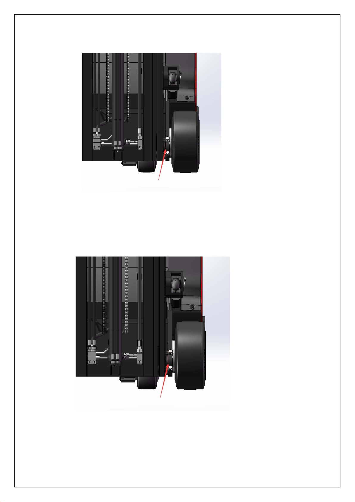
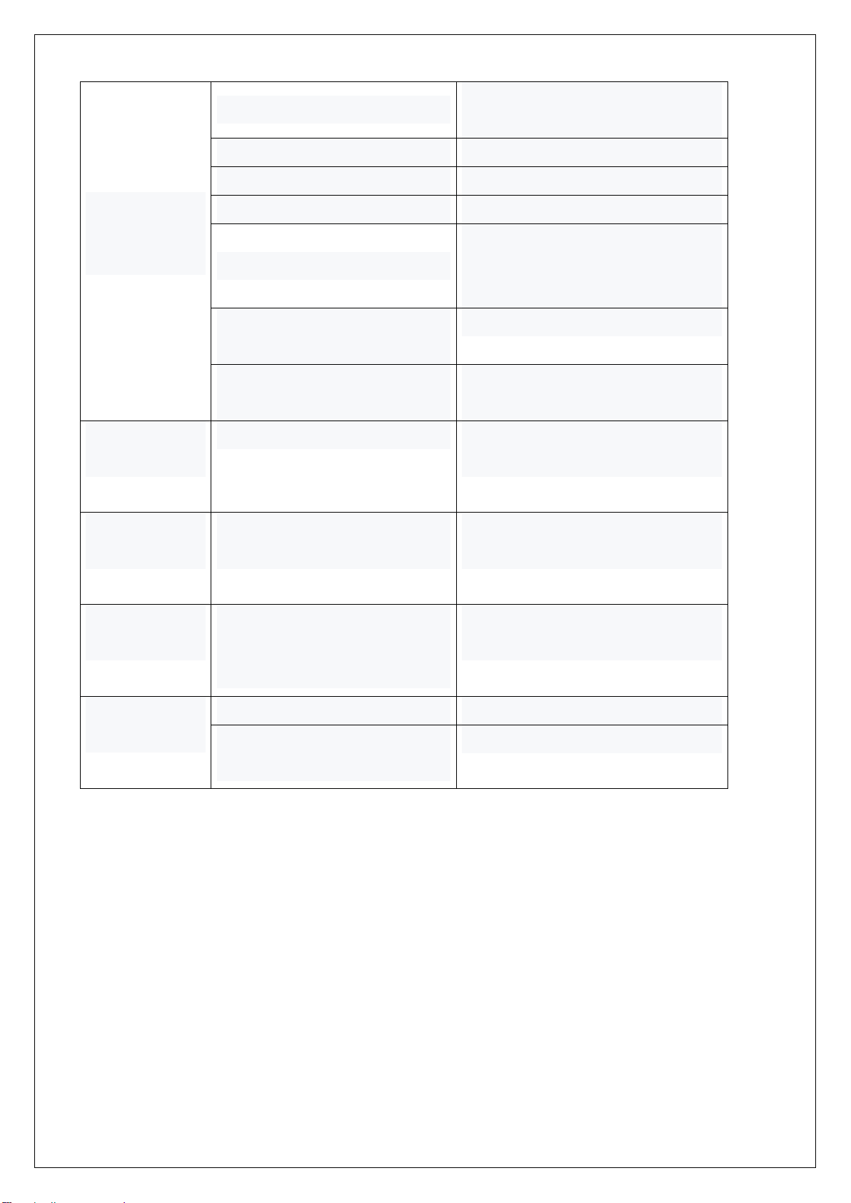
a. Battery brake adjustment.................................................................................................................................................... 12
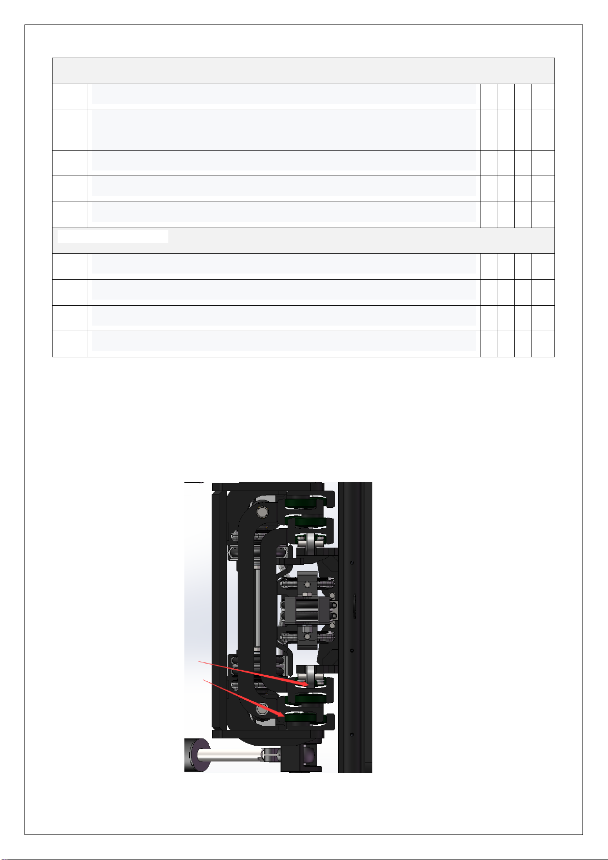
b Drive assembly disassembly............................................................................................................................................... 13
c. Drive brake disassembly ...................................................................................................................................................... 14
d. Drive internal gear bearings............................................................................................................................................... 15
e. Handle assembly...................................................................................................................................................................... 16
f. Frame breakdown ................................................................................................................................................................... 18
g. Pump station motor ................................................................................................Error! Bookmark not defined.4
5、CURTIS Handheld Unit...............................................................................................................................................................................25

2
1. Regular maintenance
Only qualified and trained personnel should perform maintenance work on this vehicle.
Before maintenance, remove the cargo from the fork and lower the fork to the lowest position.
If you need to lift the vehicle, use the specified lashing or jacking equipment. Before operation, place safety
devices (such as designated jacks, wedges or wood blocks) under the vehicle to prevent accidental drop,
movement or sliding.
Use the original parts approved and released by your dealer.
Please consider that hydraulic fluid leakage may lead to machine failure and accidents.
Pressure valve adjustment is only allowed by trained service technician.
If you need to replace wheels, casters must be round and free of abnormal wear.
Check the items on the maintenance list.
2. Maintenance List
Interval
(month)
1
3 6
12
The hydraulic system
1.1
Check the function of hydraulic system
•
1.2
Check hoses, piping and joints for tightness, sealing and damage
•
1.3
Inspect cylinder block and piston for damage, sealing and fixation
•
1.4
Visually inspect the door stand roller and inspect the roller surface for wear
•
1.5
Inspect forks and loading parts for wear and loss
•
1.6
Check load chain Settings and re-tensioning if necessary
•
1.7
Check oil level in fuel tank
•
1.8
Replacement hydraulic fluid
•
Mechanical systems
2.1
Check the fork for deformation and breakage
•
2.2
Check chassis for deformation and cracking
•

3
2.3
Check that all screws are in place
•
2.4
Check gear box for noise and leakage
•
2.5
Check wheel for deformation and damage
•
2.6
Lubricated steering bearing
•
2.7
Check and lubricate the pivot points
•
2.8
Lubricating grease nozzle
•
Electrical system
3.1
Check whether power cables are damaged
•
3.2
Check the electrical connections
•
3.3
Check the function of the emergency switch
•
3.4
Check whether the power drive system is noisy or damaged
•
3.5
Test electricity meter
•
3.6
Check whether the correct fuse is used
•
3.7
Detect warning signals
•
3.8
Check the current contactor
•
3.9
Check frame for leakage (insulation test)
•
3.10
Check the function and wear of the drive controller
•
3.11
Check the electrical system that drives the motor
•
traveling system
4.1
Check the gearbox for abnormal sound
•
4.2
Check the driving mechanism and grease it
•
4.3
Inspect driving and steering wheels for wear and damage
•
4.4
Check wheel bearing and fastening condition
•
4.5
Check the air gap of the electromagnetic brake
•
4.6
Check the lifting, forward and backward tilt and left and right movement of the
door frame
•
4.7
Check and adjust braking effect
•

4
Energy supply
5.1
Check the voltage of the battery
•
5.2
Check that battery cables are securely connected and grease the electrodes if
necessary
•
5.3
Check whether the battery cover is damaged
•
5.4
Check the main cable for damage
•
5.5
Check the start up protection program during charging
•
Monolithic Construction
6.1
Check all labels for clarity and completeness
•
6.2
Check the frame for damage
•
6.3
Check the fixing condition of lifting door frame
•
6.4
Run a test run
•
3. Lubrication point.
Lubricate marked points according to maintenance list. Required grease specification: DIN 51825
standard grease
Pic1:transmission chain

5
Pic2:The rail of gantry
Pic3:Drive axle clamp

6
4. Check and refill hydraulic oil
Recommended hydraulic oil model according to temperature:
Ambient
temperature
–5℃~25℃
>25℃
mark
HVLP 32
,
DIN 51524
HLP 46
,
DIN 51524
Viscosity
28.8-35.2
41.4 - 47
Oil
19-20L
Waste materials such as waste oil, waste batteries or other materials must be treated and recycled in
accordance with national regulations and returned to the recycling company for recycling if necessary.
The oil level should not be lower than the minimum amount required to start the vehicle.
Fill up to refueling point if necessary。
5. Fault analysis
If the vehicle continues to malfunction, follow the instructions of the manual.
6. Common fault analysis
Fault Cause
maintenance
Vehicles cannot
move
The battery connector is not
connected
Check the battery connector and
connect it if necessary
The electric lock switch is in "OFF"
position
The electric lock switch is placed in the
"0" position
The emergency stop switch is not
on
Turn on the emergency stop switch
Battery running out Check the charging status of the
battery and recharge it if necessary
The forklift is charging
Interrupt charging process
Fuse damage
Check fuse
Foot pedal switch not pressed;
handle safety switch not pressed
Step on the pedal switch and press the
handle safety switch

7
The cargo
cannot be raised
or lowered
The vehicle is not running Follow the procedure listed in the
"Vehicle cannot Move" fault
There's too little hydraulic fluid
Check hydraulic oil
Fuse damage
Check fuse
Load overweight
Note rated load
Dirty oil clogs the control valve
Check the hydraulic oil and clean the
control valve and replace the hydraulic
oil if necessary
The descent solenoid valve is not
open or damaged
Check the drop solenoid or replace it
Foot pedal switch not pressed;
handle safety switch not pressed
Step on the pedal switch and press the
handle safety switch
You can't stop
when you go up
The lifting microswitch is damaged Cut off the power supply and replace
the lifting microswitch
Moving in one
direction
Contact between micro switch and
connecting cable is not good
Check the microswitch and connecting
cable in the control handle
Traffic moves
slowly
The battery power is low, or the
corresponding cable is in poor
contact
Check the battery indicator and
corresponding cables
The vehicle
started suddenly
Controller damage
Replacing a Controller
Control forward and backward
handle is not reset
To restore or replace

8
7. Display of fault code
Steering failure code
CODE fault cause
12 Controller Overcurrent
1. The steering motor is short-circuited
13 Current Sense Fault
2. The controller fails
14 Pre-Charge Fault
1. The controller fails
15 Controller Severe Undertemp
1. The controller fails
16 Controller Severe Overtemp
1. The controller runs in a low-temperature environment
17 Severe Undervoltage
2. The temperature sensor is damaged
18 Severe Overvoltage
1. Vehicle overload
21 Motor Temp Hot Cutback
2. The controller runs in an ultra-high temperature environment
22 Controller Overtemp
3. The controller is improperly fixed
23 Motor Polarity Fault
1. The battery or battery cable is faulty
24 5V Output Failure
2. There are other heavy loads connected to the battery
31 Main Driver Fault 3. The battery is dead, or the model is different

9
32 Relay Welded
1. In RegEN mode, the battery or battery cable resistance is too
high
33 Relay Did Not Close
2. The battery cable is disconnected during regen
34 Hardware Fault
1. Vehicle overload
35 Fault Output Failed
2. The controller runs in an ultra-high temperature environment
36 Motor Stalled
1. Vehicle overload
37 Motor Open
1. Open cables to the steering motor
38 Motor Short 2. The motor is incorrectly connected
41 Command Analog1 Out of
Range
3. The controller fails
42 Command Analog2 Out of
Range
1. The steering motor is short-circuited
43 Feedback Analog1 Out of
Range
1. Analog input 1 (J1-6) is out of range
44 Feedback Analog2 Out of
Range
2. Low end of instruction (J1-14) out of range (for resistance
type)
45 Parameter Change Fault
3. The parameter Settings are incorrect
46 EEPROM Failure 1. Analog input 2 (J1-13) is out of range

10
47 Encoder Fault
2. Analog quantities 1 and 2 fail to be cross-checked
53 Home Position Not Found
3. The parameter Settings are incorrect
62 Communication Fault
1. Analog feedback input 1 (J1-11) is out of range
63 Communication Lost
2. The parameter Settings are incorrect
71 Software Fault
1. Analog feedback input 2 (J1-3) is out of range
73 Following Error
2.J1-11 and J1-3 analog cross check failed
75 Parameter Conflict
3. The parameter Settings are incorrect

11
8. Fault code of the walking controller
CODE fault cause
1
Controller Over
current 1, motor external U, V or W connection short circuit
2
Current Sensor Fault
2. Motor parameters do not match
3
Precharge Failed 3. The controller is faulty
4
Controller Severe
Undertemp
1, motor U, V, W through the stator on the car body short circuit,
resulting in leakage
5
Controller Severe
Overtemp
2. The controller is faulty
6
Severe Undervoltage 1. Negative load is connected to the positive end of the capacitor, so
that the capacitor cannot be charged normally
7
Severe Overvoltage 1. The working environment of the controller is too harsh
8
Controller Undertemp
Cutback
1. The working environment of the controller is too harsh
9
Controller Overtemp
Cutback
2. Vehicle overload
10
Undervoltage Cutback 3. The controller is incorrectly installed
11
Overvoltage Cutback 1. Battery parameters are incorrectly set
12
+5V Supply Failure 2. Power consumption of non-controller system
13
Digital Out 6 Failure
3, the battery impedance is too large
14
Digital Out 7
Overcurrent
4. The battery is disconnected
15
Motor Temp Hot
Cutback
5, the fuse is disconnected, or the main contractor is not connected
16
Motor Temp Sensor 1. The motor temperature sensor is incorrectly connected

12
17
Coil 1 Driver
Open/Short If the motor does not use a temperature sensor, the programming
parameters are "Temp Compensation and Temp"
18
Main Open/Short Cutback must be set to "OFF"
19
Coil2 Driver
Open/Short 1. Connect load open or short
20
EMBrake Open/Short 2. The connecting pin is defiled
21
Coil3 Driver
Open/Short 3. Wrong wiring
22
Coil4 Driver
Open/Short 1. Connect load open or short
23
PD Open/Short 2. The connecting pin is defiled
24
Encoder Fault 3. Wrong wiring
25
Motor Open 1. Connect the load to open or short circuit
26
Main Contactor Welded 2. The connector is defiled
27
Main Contactor Did Not
Close
3. Incorrect cables are connected
28
Throttle Wiper High 1. Connect load open or short
29
Throttle Wiper Low
2. The connecting pin is defiled
30
Pot2 Wiper High 3. Wrong wiring
31
Pot2 Wiper Low 1. Connect load open or short
32
Pot Low Overcurrent 2. The connecting pin is defiled
33
EEPROM Failure
EEPROM
3. Wrong wiring
34
HPD/Sequencing Fault 1. Connect load open or short
35
Emer Rev HPD 2. The connecting pin is defiled
36
Parameter Change Fault
3. Wrong wiring
38
VCL Runtime Error 1. Connect load open or short

13
39
External Supply Out of
Range
2. The connecting pin is defiled
40
OS General 3. Wrong wiring
41
PDO Timeout 1. Motor encoder failure
42
Stall Detected 2. Wrong wiring
43
Motor
Characterization
Fault
1, motor phase deficiency
44
Motor Type Fault 2. Wrong wiring
45
VCl/OS Mismatch 1, main contactor contact fusion
46
EM Brake Failed to Set 2. Motor U or V is disconnected, or phase is missing
47
Encoder LOS (Limited
Operating Strategy)
3. The circuit charging capacitor connected to the B+ terminal exists
48
Emer Rev Timeout 1. The main contractor is not closed
49
Illegal Model Number 2, the main contactor contact oxidation, melting
50
Dual motor Parameter Or the connection status is unstable

14
9. Wiring/circuit diagram
A. Electrical schematic diagram
3.2 hydraulic principle diagram

15
10. Hydraulic oil inspection
Appearance odor condition results
Clear not discoloration
good
good
can be used
color transparency
good
with other oil mix
check viscosity, if qualified can
continue to use
Color changes like milk
well
mixed with air and water
to separate moisture or replace
hydraulic fluid
The color becomes dark brown
not
good
for oxidation
replacement of hydraulic oil
Clear color but small black spots
good
mix with other particles
can be used after filtering
11. Steering system
The steering system consists of rotating steering wheel, steering shaft, steering gear, electromagnetic
braking, steering motor and reducer.
The drive unit is mounted on a rotary platform, and the steering function is realized by the steering motor
reducer.
The steering motor with permanent magnet is controlled by the controller. On the one hand, the steering
controller obtains the input signal from the steering wheel, on the other hand, it also obtains the signal of
the actual Angle position of the wheel.
When turning, the speed of the forklift decreases automatically

16
1. Controller 2. Rotating steering wheel 3.Electromagnetic braking 5. Steering motor 6. Reducer 7.
Tires
When the vehicle is moving forward, rotate the steering wheel in the direction of S, then the vehicle
rotation direction is S; If the steering wheel is rotated in the N direction, the whole vehicle rotates in the N
direction.
When the vehicle is driving backwards, the steering wheel rotates to the DIRECTION of S, and the
vehicle rotates to the direction of N; if the steering wheel is rotated in the N direction, the whole vehicle is
rotated in the S direction.

17
12. The braking system
Operating handle diagram

18
1. Roll forward button 2. Roll back button 3. The left button
4. Right move button 5. Horn button 6. Safety switch button
Insert the key into the key switch, turn to the right, turn the emergency stop switch in accordance with the
direction indicated by the arrow above the button, and open the control circuit. Slowly push down the foot
switch. Turn the steering wheel in the desired direction (forward or backward). Hold the handle lever
(safety switch must be pressed) to B direction, forklift forward. Hold the handle lever (safety switch must
be pressed) in the F direction, the forklift back. Observe the road condition and adjust the speed through
the handle lever. When the forklift stops running, pull the handle lever slowly to the middle O position,
and leave the pedal switch with the right foot to make the forklift stop completely. Place the fork in the
lowest position and press the safety switch to remove the key.

19
a. Hydraulic system
The hydraulic system consists of main oil pump, valve group, lifting cylinder, inclined cylinder and oil
circuit.
The oil pump motor drives the gear pump to provide hydraulic power, the lifting cylinder is responsible
for the lifting of the fork, the inclined cylinder completes the forward and backward tilt of the door frame,
and the lateral cylinder completes the left and right-side movement of the tray frame. It has been
debugged before leaving the factory. After leaving the factory, non-after-sales staff of our company or
professional maintenance personnel is strictly prohibited to adjust themselves to avoid safety accidents.
7.1 Multiple valve sets
Multi-way valve consists of valve body, solenoid valve, relief valve and so on. The pressure of the main
safety valve has been adjusted well before delivery, so users are not allowed to adjust it casually.
Other manuals for EK18RF
1
This manual suits for next models
1
Table of contents
Other EKKO Forklift manuals