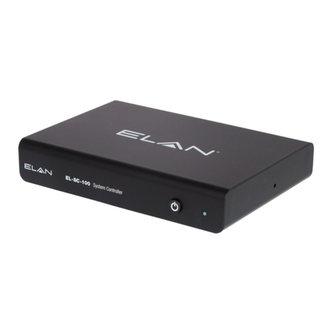
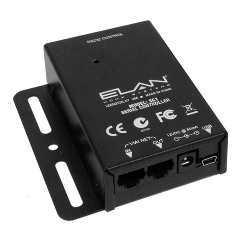
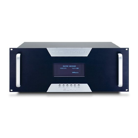
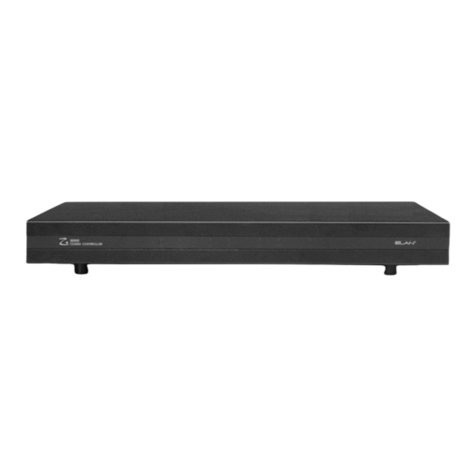
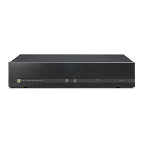
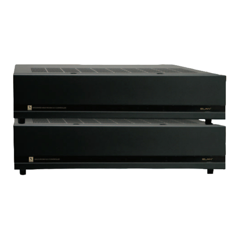
Elan SC1 User manual


© ELAN Home Systems 2008 • All rights reserved Page 1
SC-1 INSTALLATION MANUAL
ELAN HOME SYSTEMS
Items in Box
• SC-1
• RJ-45 to DB9 Adapter
• Installation Manual
• RJ-45 to RJ45 Cable

Page 2 © ELAN Home Systems 2008 • All rights reserved.
SC-1 INSTALLATION MANUAL ELAN HOME SYSTEMS
Contents
Introduction ................................................................................. 3
Features ....................................................................................... 3
System Design ............................................................................ 6
Connections ..................................................................................... 13
Operations ................................................................................... 22
Troubleshooting .............................................................................. 24
Appendix A: Specifications ...................................................... 25
Appendix B: Programming ....................................................... 26
Appendix C: RJ-45 to DB9 Wiring Code ................................ 27
Warranty ......................................................................... Back Page

© ELAN Home Systems 2008 • All rights reserved Page 3
SC-1 INSTALLATION MANUAL
ELAN HOME SYSTEMS
Introduction
The SC-1 has one Serial Port for the integration of local and system
RS-232-controlled sub-systems and components (i.e. lighting,
temperature, security), allowing wired VIA! Touch Panels, Wireless
Color Touch Panels, and Olé Touchpads to control these systems.
Independent LED activity indicator for data transmission functions
and troubleshooting, and VIA!NET ports make for easy setup. The
USB Port allows easy programming from ELAN VIA!®TOOLS and
ELAN®TOOLS.
Features
• RS-232 Serial Device Controller for Home Automation
• Single RS-232 COM Port, a low cost solution when interfacing
to a single Serial Device
• Solve control issues with devices located farther than 50 feet
from the “Head-End” such as VIAmigo and pool and spa controls
• Add an SC-1 to expand a System SS1 to customize control
options
ELAN Precision Panels save
time and make sense out
of complex wiring jobs!
+
- -
VIA!NET
16VDC / 10A
16VDC / 4A
16VDC/1.5A
1
ZONE
2
ZONE
3
ZONE
4
ZONE
SS/SC4
5
ZONE
6
ZONE
7
ZONE
8
ZONE
TO SENSE INPUTS EXT IR
1 2 3
USE STEREO 3.5mm PLUGS ONLY
4 5 6
1
TRIGGERS
2 3 4
5678
POWER

Page 4 © ELAN Home Systems 2008 • All rights reserved.
SC-1 INSTALLATION MANUAL ELAN HOME SYSTEMS
Functions & Indicators
1
5
643
2
Figure 1-1: Functions & Indicators

© ELAN Home Systems 2008 • All rights reserved Page 5
SC-1 INSTALLATION MANUAL
ELAN HOME SYSTEMS
Item# Item Function
1
RS232 Port Communicates to Serial Devices
2
LED
Indicator
Status Indicator
3
USB Port Programming
Interface
4
Power
Connector
12VDC
Connection
5
VIA!NET
OUT
RS485 Data
Connection Loop
6
VIA!NET
IN
RS485 Data
Input Connection
Table 1-1: Functions & Indicators
See Appendix C for wiring details
RJ-45 (EIA 561) to Male DB9 (DTE)

Page 6 © ELAN Home Systems 2008 • All rights reserved.
SC-1 INSTALLATION MANUAL ELAN HOME SYSTEMS
System Design
The rst step to a good design is to map the system. It is advisable
to mark up a copy of the house oor plan with speaker, keypad,
touch panel, touchpad, volume control, and equipment locations,
etc. Make sure that all locations are decided upon before pre-wiring
commences so that all necessary wiring and installation hardware is
in place. It is essential that ALL system components are accounted
for prior to the pre-wire stage.
Secondly, make a detailed list of all components. Include source
equipment, touch panels, touchpads, keypads, RS-232 controlled
devices, relay controlled devices, power supplies, and sensors. Be
sure to include necessary electrical boxes, structured wiring enclo-
sures, telephone lines, rough-in brackets, ELAN Precision Panels,
patch cables, etc.
Pre-Wire
Pre-wiring for the SC-1 requires careful system planning. Pay close
attention to where each component will be located and ensure that
the appropriate wires are run to the correct locations! Make sure to
plan for the future. It is often advantageous to pre-wire for compo-
nents that may be installed later.
Applications
The SC-1 is extremely versatile. Whether being located in the ‘head-
end’ of a central equipment rack or remotely located in the Zone or
a combination of both, the SC-1 makes adding a serial controlled
devices easy.

© ELAN Home Systems 2008 • All rights reserved Page 7
SC-1 INSTALLATION MANUAL
ELAN HOME SYSTEMS
VNET-V485/RS485
When using the SC-1 with ELAN S86A/S86P Multi-Room Controllers
ELAN recommends using the SPP Precision Panel’s Zone (X) A or B
punchdown locations. These multi-room controllers utilize V485 to
transfer information and status. The SS/SC4 Port connection on the
front of the SPP Precision Panel may also be utilized, but requires
the SC1 to be powered locally, see page 19 for more details.
The S86A/S86P Multi-Room Controller uses a VIA!NET data buss
to transmit V485 information. A basic S86A/P can take advantage
of the KP 1-6 connector for a direct link to the SC-1 when an SPP
Precision Panel is not used. Direct connection of an Olé Touch Pad
to the SC-1 streamlines the wiring network when installing a single
SC-1 to an S86P as shown in applications Figure 2-2.
Using the VIA!NET run with Cat5 cable simplies control of remotely
located RS-232 devices such as HVAC, security, pool equipment,
and ELAN’s VIAmigo.
ZNET-Z485/RS485
When using the SC-1 with ELAN S6/S12 Multi-Room Controllers
ELAN recommends using the SS/SC4 data port on the front of the
SPP Precision Panel. These multi-room controllers utilize Z485 data
to transmit information and status so the use of a precision panel is
required. A PWR3 power supply will be needed for the SC-1 in this
application, see page 19. Ensure that the SPP ZNet/VNET switch is
in the ZNET Position and the SS/SC-4 switch is in the ON position. If
a Zone installation is required with a ZNET application see page 18
for SPP ZNET Zone wiring details.

Page 8 © ELAN Home Systems 2008 • All rights reserved.
SC-1 INSTALLATION MANUAL ELAN HOME SYSTEMS
RS Serial
Adapter
RJ-45
to
RS-232
Connector
Cat-5
SPP
S6
16 VDC/
4A
PWR4
Zone
RJ-45
Wall Plate
+
--
VIA!NET
16VDC / 10A
16VDC / 4A
16VDC/1.5A
1
ZONE
2
ZONE
3
ZONE
4
ZONE
SS/SC4
5
ZONE
6
ZONE
7
ZONE
8
ZONE
TO SENSE INPUTSEXT IR
123
USE STEREO 3.5mm PLUGS ONLY
456
1
TRIGGERS
234
5 6 7 8
POWER
SC-1
Jandy
VIA!70
R
Rack
RJ-45
Wall Plate
Figure 2-1: S6 Jandy Pool Application

© ELAN Home Systems 2008 • All rights reserved Page 9
SC-1 INSTALLATION MANUAL
ELAN HOME SYSTEMS
RJ-45
to
RS-232
Connectors
Cat-5
S86P
SC-1
ZONE 4 ZONE 5 ZONE 6 VIA!NET OUT
ZONE 1 ZONE 2 ZONE 3 VIA!NET IN
2 3 45 6 7
IN
OUT
IN
OUT
SOURCE IR OUTPUTS
1 2 3 45 6
ELAN SENSE INPUTS
ZONE PRE-AMP OUTPUTS
SOURCE INPUT 4
SOURCE INPUT 8
V L R
LOOP OUTPUT 4
LOOP OUTPUT 8
V L R
1 2 3 4 5 6
PROGRAMMABLE TRIGGER OUTPUTS
ELAN RS-232
PORTS
SOURCE IR
EXPANSION PORTS
ALL IR
OUT
SYSTEM
TRIGGER
OUT
PG OUT
PG IN
MOH OUT
IN
PAGE
TRIGGER
OUT
SOURCE INPUT 3
SOURCE INPUT 7
V L R
LOOP OUTPUT 3
LOOP OUTPUT 7
V L R
SOURCE INPUT 2
SOURCE INPUT 6
V L R
LOOP OUTPUT 2
LOOP OUTPUT 6
V L R
SOURCE INPUT 1
SOURCE INPUT 5
V L R
LOOP OUTPUT 1
LOOP OUTPUT 5
V L R
V
L
R
V
L
R
V
L
R
V
L
R
V
L
R
120VAC 60Hz.
400W
1 2 3 4 5 6
81
LEXINGTON, KY USA • MADE IN CHINA
MODEL: S8.6AVP
MULTI-ROOM AUDIO/ VIDEO CONTROLLER
WARNING: DO NOT REMOVE COVER. NO USER SERVICEABLE PARTS INSIDE.
REFER SERVICE TO ELAN-APPROVED SERVICE TECHNICIAN.
ZONE 3 Olé
L
R
IR
OUT
IN
SOURCE
VIDEO
LSWP
Local Source
Wall Plate
VIA!migo RCA
A/V Cables
Cat-5 3.5mm
IR Cable
Zone
RJ-45
Wall Plate
Figure 2-2: S86P Application (No SPP)

Page 10 © ELAN Home Systems 2008 • All rights reserved.
SC-1 INSTALLATION MANUAL ELAN HOME SYSTEMS
Note: With S12, Autobuild using IR commands in VIA!TOOLS, or
Autofill using IR commands in ELANTOOLS.
Olé
Cat-5
Cat-5
S12
16 VDC/
4A
PWR4
+
--
VIA!NET
16VDC / 10A
16VDC / 4A
16VDC/1.5A
1
ZONE
2
ZONE
3
ZONE
4
ZONE
SS/SC4
5
ZONE
6
ZONE
7
ZONE
8
ZONE
TO SENSE INPUTSEXT IR
1 2 3
USE STEREO 3.5mm PLUGS ONLY
4 5 6
1
TRIGGERS
2 3 4
5678
POWER
RJ-45
to
RS-232
Connectors SC-1
L
R
IR
OUT
IN
SOURCE
VIDEO
LSWP
Local Source
Wall Plate
VIA!migo RCA
A/V Cables
Cat-5 3.5mm
IR Cable
Zone
RJ-45
Wall Plate
PWR3
Figure 2-3: S12 VIAmigo Application

© ELAN Home Systems 2008 • All rights reserved Page 11
SC-1 INSTALLATION MANUAL
ELAN HOME SYSTEMS
SPP
+
--
VIA!NET
16VDC / 10A
16VDC / 4A
16VDC/1.5A
1
ZONE
2
ZONE
3
ZONE
4
ZONE
SS/SC4
5
ZONE
6
ZONE
7
ZONE
8
ZONE
TO SENSE INPUTSEXT IR
123
USE STEREO 3.5mm PLUGS ONLY
4 5 6
1
TRIGGERS
234
5678
POWER
16VDC
10.0A
PWR10
PWR
GND
NC
COM
NO
PWR
GND
NC
COM
NO
PWR
GND
NC
COM
NO
PWR
GND
NC
COM
NO
PWR
GND
NC
COM
NO
PWR
GND
NC
COM
NO
PWR
GND
NC
COM
NO
PWR
GND
NC
COM
NO
PWR
GND
DC RELAY PWR RELAY 1 RELAY 2 RELAY 3 RELAY 4 RELAY 5 RELAY 6 RELAY 7 RELAY 8
HOST RS-232
ELAN RS-232
HOST
ELAN
COM 1
COM 3
COM 2
COM 4
COM 1
COM 2
COM 3
COM 4
ETHERNET
LINK
RX/TX
IR-LINK SENSE INPUTS
123
4 5 6
ALL IR OUTPUT
EXT IR INPUT
IR OUTPUTS
1
2
3
4
5
6
7
8
9
10
11
12 VIA-NET
PWR
IR
VIA!2SS1
12VDC
-+
LEXINGTON, KY • MADE IN CHINA
MODEL: VIA2SS1
WARNING: DO NOT REMOVE COVER.
NO USER SERVICEABLE PARTS INSIDE.
REFER SERVICE TO ELAN-APPROVED
SERVICE TECHNICIAN.
SS1
S12
VIA!NET 100’
run to Utility
Closet
RJ-45
to
RS-232
Connector SC-1
Security
Panel
RJ-45
to
RS-232
Connector
SC-1
HVAC
Panel
*SS1 COM Ports
are taken up with
Home Theater
Components
Figure 2-4: SC-1 Loop Application

Page 12 © ELAN Home Systems 2008 • All rights reserved.
SC-1 INSTALLATION MANUAL ELAN HOME SYSTEMS
RJ-45
to
RS-232
Connectors
Cat-5
S86P
SC-1
ZONE 4 ZONE 5 ZONE 6 VIA!NET OUT
ZONE 1 ZONE 2 ZONE 3 VIA!NET IN
2 3 45 6 7
IN
OUT
IN
OUT
SOURCE IR OUTPUTS
1 2 3 45 6
ELAN SENSE INPUTS
ZONE PRE-AMP OUTPUTS
SOURCE INPUT 4
SOURCE INPUT 8
V L R
LOOP OUTPUT 4
LOOP OUTPUT 8
V L R
1 2 3 4 5 6
PROGRAMMABLE TRIGGER OUTPUTS
ELAN RS-232
PORTS
SOURCE IR
EXPANSION PORTS
ALL IR
OUT
SYSTEM
TRIGGER
OUT
PG OUT
PG IN
MOH OUT
IN
PAGE
TRIGGER
OUT
SOURCE INPUT 3
SOURCE INPUT 7
V L R
LOOP OUTPUT 3
LOOP OUTPUT 7
V L R
SOURCE INPUT 2
SOURCE INPUT 6
V L R
LOOP OUTPUT 2
LOOP OUTPUT 6
V L R
SOURCE INPUT 1
SOURCE INPUT 5
V L R
LOOP OUTPUT 1
LOOP OUTPUT 5
V L R
V
L
R
V
L
R
V
L
R
V
L
R
V
L
R
120VAC 60Hz.
400W
1 2 3 4 5 6
81
LEXINGTON, KY USA • MADE IN CHINA
MODEL: S8.6AVP
MULTI-ROOM AUDIO/ VIDEO CONTROLLER
WARNING: DO NOT REMOVE COVER. NO USER SERVICEABLE PARTS INSIDE.
REFER SERVICE TO ELAN-APPROVED SERVICE TECHNICIAN.
ZONE 3 Olé
L
R
IR
OUT
IN
SOURCE
VIDEO
LSWP
Local Source
Wall Plate
VIA!migo RCA
A/V Cables
Cat-5 3.5mm
IR Cable
SPP
+
--
VIA!NET
16VDC / 10A
16VDC / 4A
16VDC/1.5A
1
ZONE
2
ZONE
3
ZONE
4
ZONE
SS/SC4
5
ZONE
6
ZONE
7
ZONE
8
ZONE
TO SENSE INPUTSEXT IR
1 2 3
USE STEREO 3.5mm PLUGS ONLY
4 5 6
1
TRIGGERS
2 3 4
5678
POWER
16VDC
10.0A
PWR10
PWR
GND
NC
COM
NO
PWR
GND
NC
COM
NO
PWR
GND
NC
COM
NO
PWR
GND
NC
COM
NO
PWR
GND
NC
COM
NO
PWR
GND
NC
COM
NO
PWR
GND
NC
COM
NO
PWR
GND
NC
COM
NO
PWR
GND
DC RELAY PWR RELAY 1 RELAY 2 RELAY 3 RELAY 4 RELAY 5 RELAY 6 RELAY 7 RELAY 8
HOST RS-232
ELAN RS-232
HOST
ELAN
COM 1
COM 3
COM 2
COM 4
COM 1
COM 2
COM 3
COM 4
ETHERNET
LINK
RX/TX
IR-LINK SENSE INPUTS
123
4 5 6
ALL IR OUTPUT
EXT IR INPUT
IR OUTPUTS
1
2
3
4
5
6
7
8
9
10
11
12 VIA-NET
PWR
IR
VIA!2SS1
12VDC
-+
LEXINGTON, KY • MADE IN CHINA
MODEL: VIA2SS1
WARNING: DO NOT REMOVE COVER.
NO USER SERVICEABLE PARTS INSIDE.
REFER SERVICE TO ELAN-APPROVED
SERVICE TECHNICIAN.
SS1
SC-1
Zone
RJ-45
Wall Plates
LCD TV
PWR3
*SS1 COM Ports
are taken up with
Home Theater
Components
Figure 2-5: S86P Application (w/SPP)

© ELAN Home Systems 2008 • All rights reserved Page 13
SC-1 INSTALLATION MANUAL
ELAN HOME SYSTEMS
Connections
This chapter describes all necessary connections for installing the
SC-1.
VIA!NET
When adding an SC-1 to expand Com Port capability use a Cat-5
wire with ELAN Standard RJ-45 pinout to connect the SC-1 to a
system’s VIA!NET when installing ELAN devices including SS1s. Set
the SPP SS/SC4 switch to the up position (ON).
VIA!NET
PORT RJ45-to-RJ45
Patch Cable
SPP
VIA!NET
IN
SC-1
Figure 3-1: VIA!NET Connection
The communication link between an SC-1, SS1 and all the wired or
wireless VIA! Touch Panels and Olé Touchpads in a system is called
the ‘VIA!NET’. All VIA!NET wire runs are “home-run” from each VIA!/
Olé location to a PVIA 1, PVIA4, PVIA10 or SPP Precision Panel,
which serve as the network hub. There are two types of VIA!NETs:
BASIC and EXTENDED.

Page 14 © ELAN Home Systems 2008 • All rights reserved.
SC-1 INSTALLATION MANUAL ELAN HOME SYSTEMS
BASIC VIA!NET
A BASIC VIA!NET has the following specications and limitations:
• Capable of supporting System SS1s, SC-1s, and a maximum
of 30 wired VIA! Touch Panels, wireless VIA!2 Touch Panels (with
their companion Zone SS1s) and/or Olé Touchpads.
• The maximum distance between an SC-1 and any one wired
VIA! Touch Panel and companion Zone SS1 or Olé Touchpad
CANNOT EXCEED 1000 feet.
• In a BASIC VIA!NET system, the combined TOTAL LENGTH of
the wire runs CANNOT EXCEED 2000 feet.
EXTENDED VIA!NET
An EXTENDED VIA!NET has the following specications and limita-
tions:
• Capable of supporting System SS1s, SC-1s and a maximum
of 30 wired VIA! Touch Panels, wireless VIA!2 Touch Panels (with
their companion Zone SS1s) and/or Olé Touchpads (same as
BASIC VIA!NET).
• The maximum distance between an SC-1 and any one wired
VIA! Touch Panel and companion Zone SS1 or Olé Touchpad
CANNOT EXCEED 1000 feet (same as BASIC VIA!NET).
• In an EXTENDED VIA!NET system the combined TOTAL
LENGTH of the wire runs within the VIA!NET CAN EXCEED 2000
feet.

© ELAN Home Systems 2008 • All rights reserved Page 15
SC-1 INSTALLATION MANUAL
ELAN HOME SYSTEMS
Even when VIA!NET Repeaters are utilized, the combined
TOTAL LENGTH of wire runs in each “sub-net” still
MUST NOT EXCEED 1000 feet.
NOTE: Use of system-specific Precision Panels for S and VIA!
is required for proper functionality when integrating serial con-
trolled devices with the SC-1.
VIA!NET Repeaters
VIA!NET Repeaters allow devices to be installed at distances that
are in excess of normal maximum wire run lengths. Punch the re-
peater down on a PVIA or other VIA!NET Precision Panel as shown
in the drawing below.
Keep in mind the following points:
• Use VIA!NET Repeaters when the TOTAL combined wire
length to all VIA! Touch Panels or SC-1 VIA!NET Ports exceeds
the 2000 ft. maximum limit.
NOTE: Wire runs WITH VIA!NET Repeaters still must not exceed
1000ft. in length.
• As many as 30 wire runs WITH VIA!NET Repeaters may
be utilized, as long as NONE of the individual runs exceed
1000 ft. in length.
• The combined length of all wire runs remaining
WITHOUT VIA!NET Repeaters (‘sub-net’) must not exceed
1000 ft.

Page 16 © ELAN Home Systems 2008 • All rights reserved.
SC-1 INSTALLATION MANUAL ELAN HOME SYSTEMS
VIA!Net Repeater
Figure 3-2: VIA!NET Repeater
All Cat-5 connections described in this manual will use ELAN’s
standard pinout conguration, as shown below.
Blue (Pin 1) - System Sense (Passthrough)
White/Blue (Pin 2) - IR Out (Passthrough)
Orange (Pin 3) - VIA!Net RS-485 -
White/Orange (Pin 4) - VIA!Net RS-485 +
Green (Pin 5) - ZNet 485 -
White/Green (Pin 6) - ZNet 485 +
Brown (Pin 7) - Ground
White/Brown (Pin 8) - +12V or +16V
BLUE
WHITE/BLUE
ORANGE
WHITE/ORANGE
GREEN
WHITE/GREEN
BROWN
WHITE/BROWN
1
2
3
4
5
6
7
8
PIN # COLOR CODE
FRONT
CABLE
Standard ELAN RJ-45 Pin-Out
TA B
Figure 3-3: VIA!NET Pin-Out

© ELAN Home Systems 2008 • All rights reserved Page 17
SC-1 INSTALLATION MANUAL
ELAN HOME SYSTEMS
SPP/VNET
When locating an SC-1 in a Zone, i.e. to control a TV or VIAmigo,
use a Cat-5 wire with ELAN Standard RJ-45 pinout to connect the
SC-1 to an SPP ZONE VIA 16V punchdown when installing the SC-
1. Set the SPP SS/SC4 switch to the up position (ON).
Z1A 16V VIA
Cat-5
Blue
White/Blue
Orange
White/Orange
Green
White/Green
Brown
White/Brown
SC-1
N/C
N/C
W/BR
BR
N/C
W/BL
W/OR
OR
Figure 3-4: SPP VNET Punchdown

Page 18 © ELAN Home Systems 2008 • All rights reserved.
SC-1 INSTALLATION MANUAL ELAN HOME SYSTEMS
SPP/ZNET
When a Zone application is necessary for S6/S12 Multi-Room
controllers, use a Cat-5 wire with ELAN Standard RJ-45 pinout to
connect the SC-1 to an SPP ZONE VIA 16V punchdown and the
RS485 expansion block. Connect the IR, V485+/-, GND, and +16V to
the ZONE VIA Punchdown and the Z485+/- to the RS485 Expansion
block when installing the SC-1. Set the SPP VNET/ZNET switch to
the ZNET position. Set the SPP SS/SC4 switch to the up position
(ON).
Cat-5
SC-1
White/Green
Green
RS 485 Expansion
-
+
Z1A 16V VIA
Blue
White/Blue
Orange
White/Orange
Green
White/Green
Brown
White/Brown
N/C
N/C
W/BR
BR
N/C
W/BL
W/OR
OR
-
+
-
+
-
+
Figure 3-5: SPP ZNET Punchdown
Other manuals for SC1
1
Table of contents
Other Elan Controllers manuals
Popular Controllers manuals by other brands

Toshiba
Toshiba TS3000 Series instruction manual

Emerson
Emerson Copeland XC643 Application Engineering Bulletin

Regal-Beloit
Regal-Beloit Marathon Electric PM300 instruction manual

AMCOL
AMCOL 6000-ETC Operator's manual

Sumpo Electric Co., Ltd.
Sumpo Electric Co., Ltd. P9000 instruction manual

DEXAPLAN
DEXAPLAN SL 614 - 2 DU 5-2008 manual