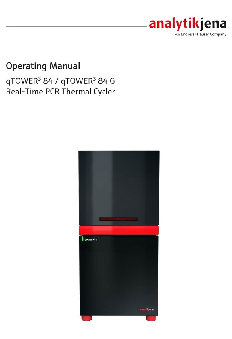
Endress+Hauser Analytik Jena CyBio FeliX User manual
Other Endress+Hauser Laboratory Equipment manuals
Endress+Hauser
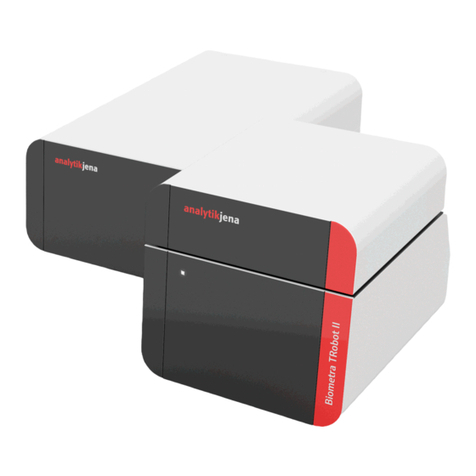
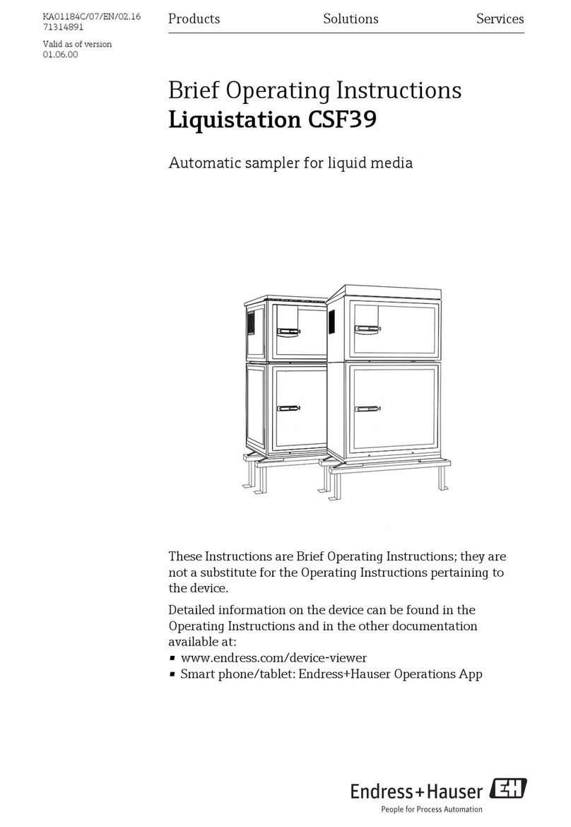
Endress+Hauser Analytik Jena Biometra TRobot II 96 G User manual
Endress+Hauser
Endress+Hauser Liquistation CSF39 Technical specifications
Endress+Hauser
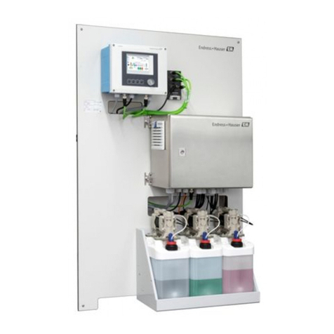
Endress+Hauser Liquiline Control CDC90 User manual
Endress+Hauser
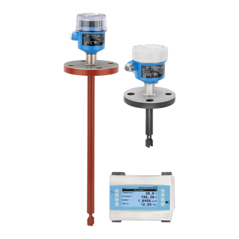
Endress+Hauser Liquiphant FTL62 Density User manual
Endress+Hauser
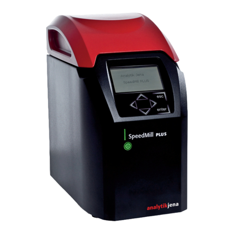
Endress+Hauser Analytik Jena SpeedMill PLUS User manual
Endress+Hauser
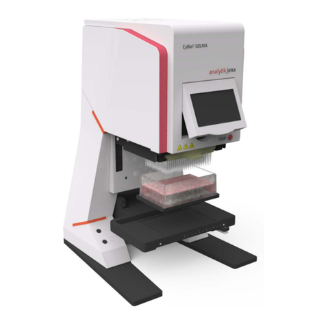
Endress+Hauser Analytik Jena CyBio SELMA User manual
Endress+Hauser
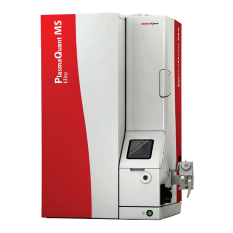
Endress+Hauser Analytik Jena PlasmaQuant MS Series User manual

Endress+Hauser
Endress+Hauser Liquistation CSF48 Manual
Endress+Hauser
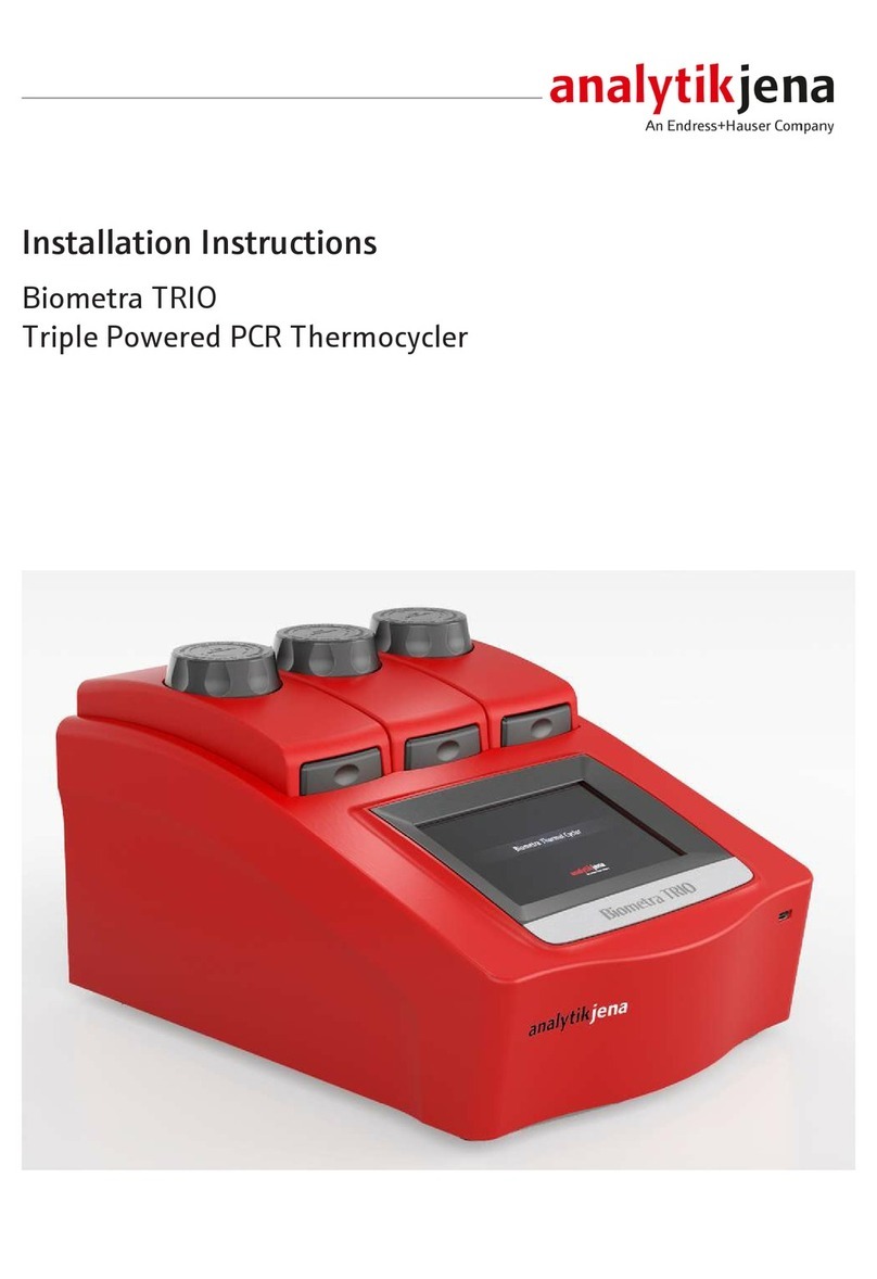
Endress+Hauser Analytik Jena Biometra TRIO User manual
Endress+Hauser
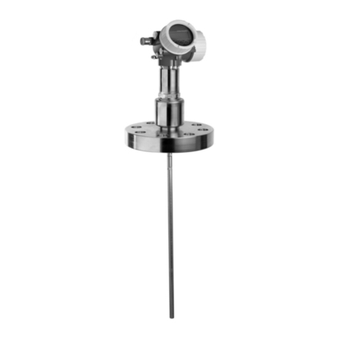
Endress+Hauser Levelflex FMP51 Installation instructions
Endress+Hauser
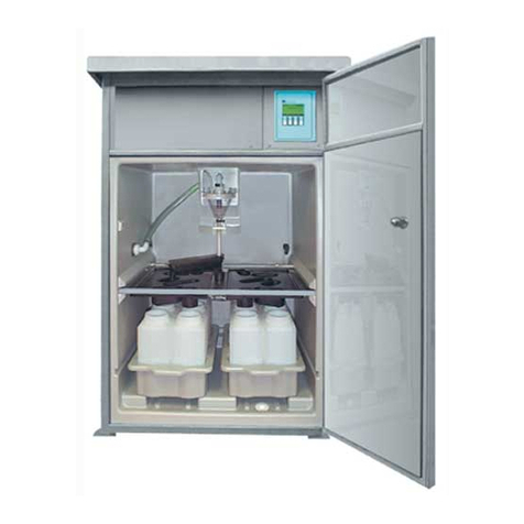
Endress+Hauser ASP Station 2000 User manual
Endress+Hauser
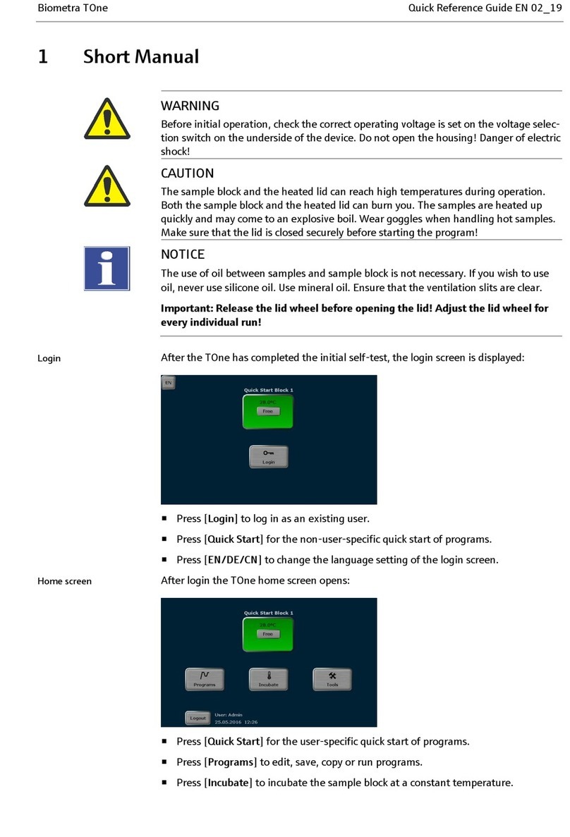
Endress+Hauser Analytik Jena Biometra TOne How to use

Endress+Hauser
Endress+Hauser Analytik Jena Biometra TAdvanced 96 User manual

Endress+Hauser
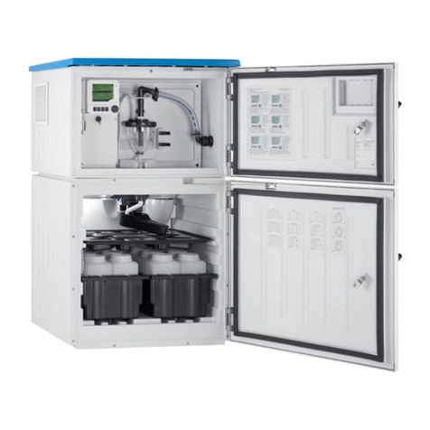
Endress+Hauser Liquistation CSF39 User manual
Endress+Hauser
Endress+Hauser Liquistation CSF34 User manual
Endress+Hauser
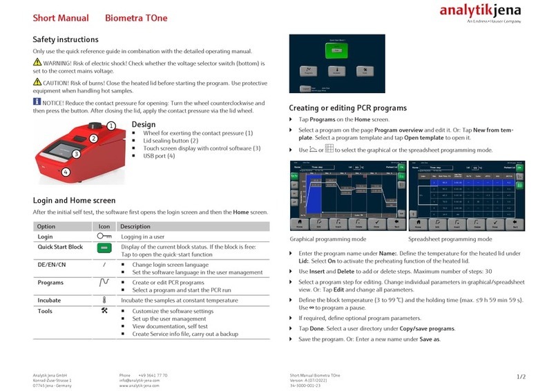
Endress+Hauser analytikjena Biometra TOne How to use
Endress+Hauser
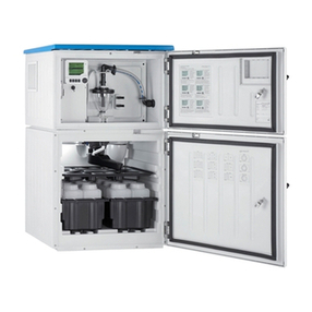
Endress+Hauser Liquistation CSF48 Manual
Endress+Hauser
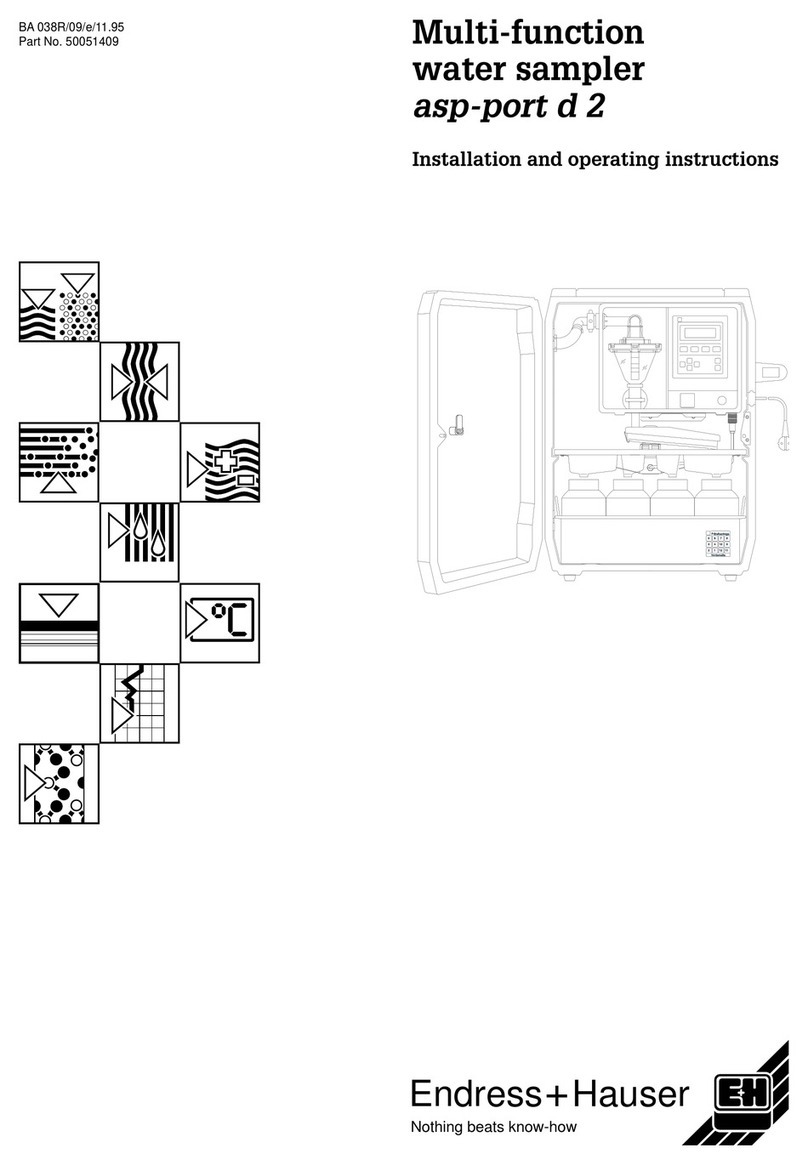
Endress+Hauser asp-port d 2 User manual
Endress+Hauser
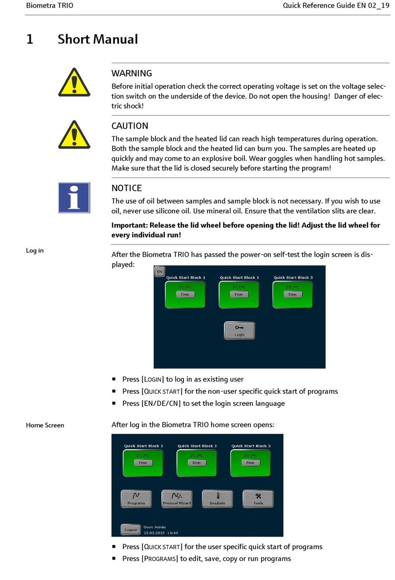
Endress+Hauser Analytik Jena Biometra TRIO User manual
Endress+Hauser
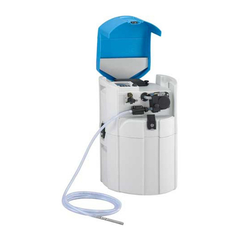
Endress+Hauser Liquiport 2010 CSP44 Technical specifications
Popular Laboratory Equipment manuals by other brands

Agilent Technologies
Agilent Technologies 5800 ICP-OES user guide

NI
NI PXI-5422 CALIBRATION PROCEDURE

Collomix
Collomix Aqix operating instructions

SPEX SamplePrep
SPEX SamplePrep 6875 Freezer/Mill Series operating manual

Ocean Insight
Ocean Insight FLAME-NIR+ Installation and operation manual

Parker
Parker ALIGN-MG-NA Installation, operation and maintenance manual

