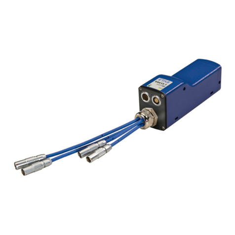
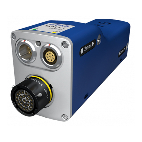
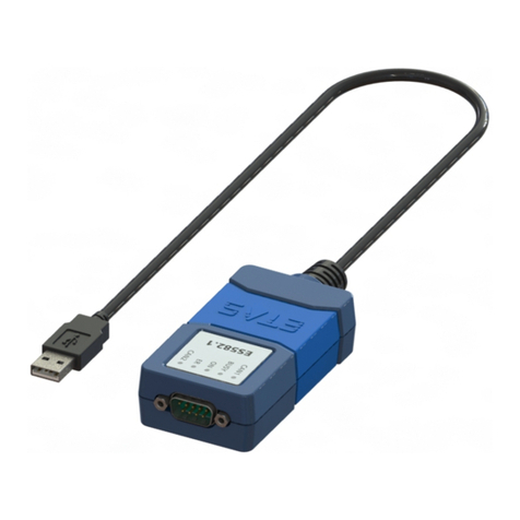
ETAS ES583.1 User manual

www.etas.com
ES583.1
FlexRay Bus Interface USB Module
User’s Guide

Copyright
The data in this document may not be altered or amended without special noti-
fication from ETAS GmbH. ETAS GmbH undertakes no further obligation in
relation to this document. The software described in it can only be used if the
customer is in possession of a general license agreement or single license.
Using and copying is only allowed in concurrence with the specifications
stipulated in the contract.
Under no circumstances may any part of this document be copied, reproduced,
transmitted, stored in a retrieval system or translated into another language
without the express written permission of ETAS GmbH.
© Copyright 2020 ETAS GmbH, Stuttgart
The names and designations used in this document are trademarks or brands
belonging to the respective owners.
ES583.1 - User's Guide R04 EN - 06.2020

ETAS Contents
Contents
ES583.1 - User's Guide 3
1 About this Document . . . . . . . . . . . . . . . . . . . . . . . . . . . . . . . . . . . . . . . . . . . . . . . . . . . 5
1.1 Classification of Safety Messages . . . . . . . . . . . . . . . . . . . . . . . . . . . . . . . . . . . . . . . . . . 5
1.2 Presentation of Instructions . . . . . . . . . . . . . . . . . . . . . . . . . . . . . . . . . . . . . . . . . . . . . . . 5
1.3 Typographical Conventions . . . . . . . . . . . . . . . . . . . . . . . . . . . . . . . . . . . . . . . . . . . . . . . . 6
1.4 Presentation of Supporting Information . . . . . . . . . . . . . . . . . . . . . . . . . . . . . . . . . . . . . 6
2 General . . . . . . . . . . . . . . . . . . . . . . . . . . . . . . . . . . . . . . . . . . . . . . . . . . . . . . . . . . . . . . 7
2.1 Basic safety notices . . . . . . . . . . . . . . . . . . . . . . . . . . . . . . . . . . . . . . . . . . . . . . . . . . . . . . 7
2.1.1 Intended use . . . . . . . . . . . . . . . . . . . . . . . . . . . . . . . . . . . . . . . . . . . . . . . . . . . . 7
2.2 RoHS conformity . . . . . . . . . . . . . . . . . . . . . . . . . . . . . . . . . . . . . . . . . . . . . . . . . . . . . . . . . 8
2.3 CE marking . . . . . . . . . . . . . . . . . . . . . . . . . . . . . . . . . . . . . . . . . . . . . . . . . . . . . . . . . . . . . . 8
2.4 Product return and recycling . . . . . . . . . . . . . . . . . . . . . . . . . . . . . . . . . . . . . . . . . . . . . . . 9
2.5 Identifications on the product . . . . . . . . . . . . . . . . . . . . . . . . . . . . . . . . . . . . . . . . . . . . . 10
2.6 About this manual . . . . . . . . . . . . . . . . . . . . . . . . . . . . . . . . . . . . . . . . . . . . . . . . . . . . . . . 10
2.7 Scope of supply . . . . . . . . . . . . . . . . . . . . . . . . . . . . . . . . . . . . . . . . . . . . . . . . . . . . . . . . . 10
2.8 Additional information . . . . . . . . . . . . . . . . . . . . . . . . . . . . . . . . . . . . . . . . . . . . . . . . . . . 10
3 Hardware description . . . . . . . . . . . . . . . . . . . . . . . . . . . . . . . . . . . . . . . . . . . . . . . . 11
3.1 Overview . . . . . . . . . . . . . . . . . . . . . . . . . . . . . . . . . . . . . . . . . . . . . . . . . . . . . . . . . . . . . . . 11
3.2 Properties . . . . . . . . . . . . . . . . . . . . . . . . . . . . . . . . . . . . . . . . . . . . . . . . . . . . . . . . . . . . . . 11
3.3 Housing . . . . . . . . . . . . . . . . . . . . . . . . . . . . . . . . . . . . . . . . . . . . . . . . . . . . . . . . . . . . . . . . 12
3.4 LEDs . . . . . . . . . . . . . . . . . . . . . . . . . . . . . . . . . . . . . . . . . . . . . . . . . . . . . . . . . . . . . . . . . . . 12
3.4.1 Operating state of the module. . . . . . . . . . . . . . . . . . . . . . . . . . . . . . . . . . . . 13
3.4.2 Function state of FlexRay interface . . . . . . . . . . . . . . . . . . . . . . . . . . . . . . . 13
3.5 Block diagram. . . . . . . . . . . . . . . . . . . . . . . . . . . . . . . . . . . . . . . . . . . . . . . . . . . . . . . . . . . 14
3.6 USB port. . . . . . . . . . . . . . . . . . . . . . . . . . . . . . . . . . . . . . . . . . . . . . . . . . . . . . . . . . . . . . . . 14
3.7 FlexRay interface (FLX1, FLX2) . . . . . . . . . . . . . . . . . . . . . . . . . . . . . . . . . . . . . . . . . . . . 14
3.7.1 Properties . . . . . . . . . . . . . . . . . . . . . . . . . . . . . . . . . . . . . . . . . . . . . . . . . . . . . 14
3.7.2 Bus termination resistor . . . . . . . . . . . . . . . . . . . . . . . . . . . . . . . . . . . . . . . . . 15
3.7.3 Synchronization nodes . . . . . . . . . . . . . . . . . . . . . . . . . . . . . . . . . . . . . . . . . . 15
3.8 Firmware update . . . . . . . . . . . . . . . . . . . . . . . . . . . . . . . . . . . . . . . . . . . . . . . . . . . . . . . . 15
4 Startup . . . . . . . . . . . . . . . . . . . . . . . . . . . . . . . . . . . . . . . . . . . . . . . . . . . . . . . . . . . . . 16
4.1 Preparing the installation . . . . . . . . . . . . . . . . . . . . . . . . . . . . . . . . . . . . . . . . . . . . . . . . . 16
4.1.1 USB driver . . . . . . . . . . . . . . . . . . . . . . . . . . . . . . . . . . . . . . . . . . . . . . . . . . . . . 16
4.1.2 Checking system requirements. . . . . . . . . . . . . . . . . . . . . . . . . . . . . . . . . . . 16
4.1.3 CD-ROM . . . . . . . . . . . . . . . . . . . . . . . . . . . . . . . . . . . . . . . . . . . . . . . . . . . . . . . 16
4.2 Installing the USB driver . . . . . . . . . . . . . . . . . . . . . . . . . . . . . . . . . . . . . . . . . . . . . . . . . . 16
4.3 Uninstalling the USB driver. . . . . . . . . . . . . . . . . . . . . . . . . . . . . . . . . . . . . . . . . . . . . . . . 18
4.4 Verifying the installation of the USB driver . . . . . . . . . . . . . . . . . . . . . . . . . . . . . . . . . . 19
4.5 Connection to the PC . . . . . . . . . . . . . . . . . . . . . . . . . . . . . . . . . . . . . . . . . . . . . . . . . . . . 20
Contents

ETAS Contents
ES583.1 - User's Guide 4
5 Troubleshooting Problems . . . . . . . . . . . . . . . . . . . . . . . . . . . . . . . . . . . . . . . . . . . . 21
5.1 Displays of the LEDs . . . . . . . . . . . . . . . . . . . . . . . . . . . . . . . . . . . . . . . . . . . . . . . . . . . . . 21
5.2 Problems with the ES583.1 . . . . . . . . . . . . . . . . . . . . . . . . . . . . . . . . . . . . . . . . . . . . . . . 21
6 Technical Data . . . . . . . . . . . . . . . . . . . . . . . . . . . . . . . . . . . . . . . . . . . . . . . . . . . . . . 23
6.1 General data . . . . . . . . . . . . . . . . . . . . . . . . . . . . . . . . . . . . . . . . . . . . . . . . . . . . . . . . . . . . 23
6.1.1 Standards . . . . . . . . . . . . . . . . . . . . . . . . . . . . . . . . . . . . . . . . . . . . . . . . . . . . . 23
6.1.2 Ambient conditions . . . . . . . . . . . . . . . . . . . . . . . . . . . . . . . . . . . . . . . . . . . . . 23
6.1.3 Maintenance of the product. . . . . . . . . . . . . . . . . . . . . . . . . . . . . . . . . . . . . . 23
6.1.4 Cleaning the product . . . . . . . . . . . . . . . . . . . . . . . . . . . . . . . . . . . . . . . . . . . . 23
6.1.5 Mechanical data. . . . . . . . . . . . . . . . . . . . . . . . . . . . . . . . . . . . . . . . . . . . . . . . 24
6.2 System requirements . . . . . . . . . . . . . . . . . . . . . . . . . . . . . . . . . . . . . . . . . . . . . . . . . . . . 24
6.2.1 Hardware . . . . . . . . . . . . . . . . . . . . . . . . . . . . . . . . . . . . . . . . . . . . . . . . . . . . . . 24
6.2.2 Software. . . . . . . . . . . . . . . . . . . . . . . . . . . . . . . . . . . . . . . . . . . . . . . . . . . . . . . 25
6.3 Electrical data. . . . . . . . . . . . . . . . . . . . . . . . . . . . . . . . . . . . . . . . . . . . . . . . . . . . . . . . . . . 26
6.3.1 Voltage supply . . . . . . . . . . . . . . . . . . . . . . . . . . . . . . . . . . . . . . . . . . . . . . . . . 26
6.3.2 FlexRay interface (FLX1 and FLX2) . . . . . . . . . . . . . . . . . . . . . . . . . . . . . . . 26
6.4 Terminal assignment . . . . . . . . . . . . . . . . . . . . . . . . . . . . . . . . . . . . . . . . . . . . . . . . . . . . 27
7 Cables and Accessories . . . . . . . . . . . . . . . . . . . . . . . . . . . . . . . . . . . . . . . . . . . . . . 28
7.1 Cable CBF100. . . . . . . . . . . . . . . . . . . . . . . . . . . . . . . . . . . . . . . . . . . . . . . . . . . . . . . . . . . 28
7.2 FlexRay termination resistor . . . . . . . . . . . . . . . . . . . . . . . . . . . . . . . . . . . . . . . . . . . . . . 30
8 Order Information. . . . . . . . . . . . . . . . . . . . . . . . . . . . . . . . . . . . . . . . . . . . . . . . . . . . 31
8.1 ES583.1 . . . . . . . . . . . . . . . . . . . . . . . . . . . . . . . . . . . . . . . . . . . . . . . . . . . . . . . . . . . . . . . 31
8.2 Accessories . . . . . . . . . . . . . . . . . . . . . . . . . . . . . . . . . . . . . . . . . . . . . . . . . . . . . . . . . . . . 31
8.2.1 FlexRay interface cable . . . . . . . . . . . . . . . . . . . . . . . . . . . . . . . . . . . . . . . . . 31
8.2.2 FlexRay termination resistor . . . . . . . . . . . . . . . . . . . . . . . . . . . . . . . . . . . . . 31
9 Contact Information. . . . . . . . . . . . . . . . . . . . . . . . . . . . . . . . . . . . . . . . . . . . . . . . . . 32
Figures . . . . . . . . . . . . . . . . . . . . . . . . . . . . . . . . . . . . . . . . . . . . . . . . . . . . . . . . . . . . 33
Index . . . . . . . . . . . . . . . . . . . . . . . . . . . . . . . . . . . . . . . . . . . . . . . . . . . . . . . . . . . . . . 34

ETAS About this Document
ES583.1 - User's Guide 5
1 About this Document
1.1 Classification of Safety Messages
The safety messages used here warn of dangers that can lead to personal
injury or damage to property:
1.2 Presentation of Instructions
The target to be achieved is defined in the heading. The necessary steps for his
are in a step-by-step guide:
Target definition
1. Step 1
2. Step 2
3. Step 3
> Result
DANGER
indicates a hazardous situation with a high risk of death or serious injury if
not avoided
WARNING
indicates a hazardous situation of medium risk which could result in death or
serious injury if not avoided.
CAUTION
indicates a hazardous situation of low risk which may result in minor or
moder-ate injury if not avoided.
NOTICE
indicates a situation which may result in damage to property if not avoided.

ETAS About this Document
ES583.1 - User's Guide 6
1.3 Typographical Conventions
Hardware
1.4 Presentation of Supporting Information
Bold Menu commands, buttons, labels of the product
Italic Emphasis on content and newly introduced terms
NOTE
Contains additional supporting information.

ETAS General
ES583.1 - User's Guide 7
2 General
The introductory chapter provides information about the basic safety notices,
product return and recycling, use of this manual, system requirements for oper-
ating the module, scope of supply and additional information.
2.1 Basic safety notices
Requirements for users and duties for operators
The product may be assembled, operated and maintained only if you have the
necessary qualification and experience for this product. Improper use or use by
a user without sufficient qualification can lead to damages or injuries to one's
health or damages to property.
General safety at work
The existing regulations for safety at work and accident prevention must be
followed.
2.1.1 Intended use
This product was developed and approved for automotive applications. For use
in other application areas, please contact your ETAS contact partner.
Requirements for operation
The following requirements are necessary for safe operation of the module:
• Observe the notes for the ambient conditions (see chapter 6.1.2
on page 23).
• Ensure compliance with the connection and settings values (see chapter
6.2.1 on page 24).
• Use the product only according to the specifications ion the correspond-
ing user's guide. For any other use, the product safety is not ensured.
• Observe the regulations concerning electrical safety and the laws and
regulations concerning occupational safety applicable at the application
site!
• Do not use the product in a potentially explosive atmosphere.
WARNING
This is a class A product. In a domestic environment this product may cause
radio interference in which case the user may be required to take adequate
measures.

ETAS General
ES583.1 - User's Guide 8
Opening the module
Requirements for the technical state of the product
The product is designed in accordance with state-of-the-art technology and
recognized safety rules. The product may be operated only in a technically flaw-
less condition and according to the intended purpose and with regard to safety
and dangers as stated in the respective product documentation. If the product
is not used according to its intended purpose, the protection of the product
may be impaired.
Maintenance and cleaning
The product is maintenance-free. For cleaning, use a clean and dry cloth.
2.2 RoHS conformity
European Union
The EU guideline 2002/95/EU limits the use of certain dangerous materials for
electric and electronic devices (RoHS conformity).
ETAS confirms that the product meets this directive applicable in the European
Union.
China
With the China RoHS identification attached to the product or its packaging,
ETAS confirms that the product meets the guidelines of the "China RoHS"
(Management Methods for Controlling Pollution Caused by Electronic Informa-
tion Products Regulation) applicable in the People's Republic of China.
2.3 CE marking
With the CE marking attached to the product or its packaging, ETAS confirms
that the product corresponds to the product-specific, applicable European
Directives. The CE Declaration of Conformity for the product is available upon
request.
CAUTION
Loss of Features as defined by IP30!
Do not open or change the module housing!
Works on the module housing may be executed only by qualified technical
personnel.
CAUTION
Damage or destruction of module is possible!
Do not open or change the module housing!
Work on the module housing may only be performed by qualified personnel.

ETAS General
ES583.1 - User's Guide 9
2.4 Product return and recycling
The European Union (EU) released the Directive for Waste Electrical and Elec-
tronic Equipment - WEEE to ensure the setup of systems for collecting, treating
and recycling electronic waste in all countries of the EU.
This ensures that the devices are recycled in a resource-friendly way that does
not represent any risk to personal health and the environment.
Fig. 2-1WEEE symbol
The WEEE symbol (see Fig. 2-1 on page 9) on the product or its packaging iden-
tifies that the product may not be disposed of together with the remaining
trash.
The user is obligated to separately collect old devices and provide them to the
WEEE return system for recycling.
The WEEE Directive applies to all ETAS devices, but not to external cables or
batteries.
Additional information about the recycling program of ETAS GmbH is available
from the ETAS sales and service locations (see chapter 9 on page 32).

ETAS General
ES583.1 - User's Guide 10
2.5 Identifications on the product
The following symbols are used for identifying the product:
Please observe the information in the chapter “Technical Data” on page 23.
2.6 About this manual
2.7 Scope of supply
Prior to the initial commissioning of your ES583.1, please check whether the
module was delivered with all required components (see chapter 8.1
on page 31).
Additional cables and adapters can be obtained separately from ETAS. A list of
available accessories and their order designation is located in chapter 8.2
on page 31 of this manual or in the ETAS product catalog.
2.8 Additional information
The configuration instructions for the ES583.1 under INCA can be found in the
corresponding software documentation.
Symbol Description
The User's Guide must be read prior to the startup of the
product!
Terminal assignment (see chapter “Terminal assign-
ment” on page 27)
Operating voltage range (DC voltage)
Marking for CE conformity, see chapter 2.3 on page 8
Marking for RoHS, see chapter on page 8

ETAS Hardware description
ES583.1 - User's Guide 11
3 Hardware description
The "Hardware description" chapter provides an overview of the ES583.1 mod-
ule, the LEDs, the block diagram, the power supply, the interfaces and the firm-
ware update.
3.1 Overview
The ES58x series consists of a series of compact ECU and bus interface mod-
ule to cost-efficiently connect vehicle buses with the PC.
The compact ES583.1 module is equipped with a FlexRay interface at a DSUB9
plug connector and with a USB port for connection to the PC. The Y-shaped
cable CBCF100 connects the SUB-D plug connector of the module with the
FlexRay channels.
The ES583.1 supports a FlexRay node with two redundantly usable FlexRay
channels and can be used in a variety of applications for analyzing the commu-
nication on the FlexRay bus.
With the efficient data transmission to the HOST PC, the module is suitable for
the calibration as well as flashing of FlexRay ECUs.
Fig. 3-1ES583.1 module (top view)
The ES583.1 is integrated in the ETAS application software INCA and supports
the protocols XCP and UDS.
The installation and configuration effort is minimal, an external voltage supply
is not required.
The ES583.1 module and the corresponding CBF100 cable are designed for
use in the lab, at the test bench and in the passenger cell of motor vehicles.
3.2 Properties
• HOST interface
– USB 2.0 high-speed port
• FlexRay interface
– Connection via standard 9-pin SUB-D plug connector in accordance
with FlexRay EPL specification V2.1 Rev. A
– 1 x FlexRay Bus (channel A + B), in accordance with FlexRay protocol
specification V 2.1 Rev. A
– Electrical isolation to HOST interface
• 1 FlexRay node with two redundantly usable FlexRay channels

ETAS Hardware description
ES583.1 - User's Guide 12
– BOSCH E-Ray-based FlexRay communication controller, compatible
with the FlexRay protocol specification V2.1
– Support of future FlexRay versions through firmware update
– Configuration of the FlexRay node in the application software, e.g. in
INCA, by importing the Fibex file
• 1 internal FlexRay node for the synchronization of both FlexRay chan-
nels:
– Exclusive use as FlexRay synchronization node is possible
– Individual FlexRay nodes/ECUs that are not located on a FlexRay bus
can be synchronized automatically with this node (e.g. for flashing
ECUs)
• Automotive-capable module that is suitable for use in the development
environment and in the vehicle on test courses.
– Compact dimensions (approx. 100 mm x 40 mm x 20 mm)
– Immune to ambient conditions (temperature, EMC)
– High level of mechanical stability and robustness
• Part of the ETAS Tool Suite
Complete technical data for the ES583.1 module can be found in the chapter
“Technical Data” on page 23.
3.3 Housing
The compact plastic housing offers not only high mechanical stability, but also
a non-slip surface for safe handling.
Connections
A USB cable with connector is permanently attached at the rear for the connec-
tion to the HOST PC. The SUB-D plug connector for connection to the FlexRay
bus is located at the front.
Serial number
The serial number of the module is located at the bottom of the device.
3.4 LEDs
The ES583.1 is equipped with an LED to display the operating state of the mod-
ule and with two LEDs to display the function of both FlexRay channels FLX1
and FLX2. The following flashing codes are used for the LEDs:
Fig. 3-2LED flashing codes
1342t(s)
Off
Off
On
On
LED
LEDFlashCode1
LEDFlashCode2

ETAS Hardware description
ES583.1 - User's Guide 13
3.4.1 Operating state of the module
At the top of the module is the LED ON/ER to display the operating and error
state of the module (see Fig. 3-1 on page 11).
• Operating state
• Error states or firmware update of the module
• Overtemperature inside the housing
Functional states of the module (LED "ON/ER")
The LED ON/ER is used to indicate the following functional states:
3.4.2 Function state of FlexRay interface
Function states of FlexRay channels (LEDs FLX1 and FLX2)
To display the function state of the FlexRay node, one LED is assigned to each
of the two FlexRay channels:
• LED FLX1: FlexRay channel A
• LED FLX2: FlexRay channel B
Meaning LED ON/ER State Description
Power Off Off Switched off
Green Normal operat-
ing mode
Active, operational
Error Off No error Error-free function
Red Functional error Return the module to
ETAS for repair.
Flashing red
(code 2)
Critical operat-
ing state / soft-
ware update is
active
Firmware update is
being performed. Do not
disconnect the module
from the PC!
Temperature in the
module is too high, func-
tion is disabled.
LED FLX1 LED FLX2 Function state
Off Off FlexRay node inactive,
(FlexRay controller is not configured)
Flashing yellow
(code 1)
Off FlexRay channel A active,
waiting for synchronization
Yellow Off FlexRay channel A active,
synchronized, ready for data exchange
Off Flashing yellow
(code 1)
FlexRay channel B active,
waiting for synchronization

ETAS Hardware description
ES583.1 - User's Guide 14
3.5 Block diagram
Fig. 3-3Block diagram
3.6 USB port
The ES583.1 must be connected to a USB 2.0 high-speed port (480 Mbit/s).
Since the module is supplied with power via the USB port, it must provide an
output current of 500 mA (USB 2.0 high power).
USB ports that can provide only a current of 100 mA are not being supported
(USB 2.0 low power). In case of insufficient current supply, the ES583.1 does
not boot and is not recognized as a USB device by the PC.
3.7 FlexRay interface (FLX1, FLX2)
The ES583.1 features a FlexRay interface with two channels (channel A and
channel B) that are routed to a 9-pin DSUB plug connector FLX1/FLX2. The
FlexRay channels A (FLX1) and B (FLX2) are completely independent channels
with separate connections.
The FlexRay interface is electrically isolated from the USB port. No electrical
decoupling exists between the FlexRay channels.
Operation of the module at USB 1.0 interfaces is not supported.
The module must be directly connected to the USB port of your PC. The use of
USB-cables extending the connection between the ES583.1 and the PC is not
allowed.
3.7.1 Properties
The FlexRay applications supported by the ES583.1 are listed in an overview in
chapter on page 25.
Off Yellow FlexRay channel B active,
synchronized, ready for data exchange
Flashing yellow
(code 1)
Flashing yellow
(code 1)
FlexRay node active (channel A and chan-
nel B), waiting for synchronization
Yellow Yellow FlexRay node active (channel A and chan-
nel B), synchronized, ready for data
exchange
LED FLX1 LED FLX2 Function state
USB
ES583.1
Power
Supply
FlexRay
Transceiver
Channel B
FlexRay
Transceive r
Channel A
FLX1/ FLX 2
FlexRay
Synch Node
Flash
Microc ontroller
LED SRAM
FlexRay
Controller

ETAS Hardware description
ES583.1 - User's Guide 15
3.7.2 Bus termination resistor
The FlexRay specification allows the design of different bus topologies, such as
passive bus, passive star or active star.
Each of the topologies requires a corresponding bus termination. The FlexRay
termination selected by ETAS in the context of the FlexRay specification mea-
sures 100 ohm. To support the design in FlexRay networks, ETAS offers Flex-
Ray cables and matching FlexRay terminations. The terminations must be
connected to the cable or the plug.
3.7.3 Synchronization nodes
After the start of a FlexRay network, the local clock generators of all nodes of
the network must be synchronized. Prerequisites for the synchronization pro-
cess are at least two nodes that can send sync frames (synchronization
nodes). The other nodes of the network synchronize themselves by analyzing
the occurrence of the sync frame and adjusting their local clock generator.
The FlexRay interface of the ES583.1 is equipped with an additional internal
synchronization node. The synchronization node can take over only synchroni-
zation functions and is internally connected with the FlexRay channels FLX1
and FLX2.
If this synchronization node sends Start-up/Sync messages as the second
node of the FlexRay network, then FlexRay networks in which no other nodes
with synchronization module exist can be started and synchronized with a sin-
gle ES583.1 module.
Application examples
• Testing/starting up FlexRay ECUs outside of FlexRay networks
• Flashing ECUs via FlexRay
3.8 Firmware update
The firmware of the ES583.1 can be updated by the user so that future versions
of the module can also be used. The firmware update is done with the help of
the service software "Hardware Service Pack" (HSP) from the connected PC.
NOTE
During a firmware update, the USB connection to the PC must not be discon-
nected!

ETAS Startup
ES583.1 - User's Guide 16
4 Startup
The "Startup” chapter describes the preparation of the installation, the Installa-
tion, the uninstallation as well as checking the installation of the USB drivers for
the ES583.1.
4.1 Preparing the installation
4.1.1 USB driver
4.1.2 Checking system requirements
Verify that your PC meets the system requirements.
To install the USB driver on the PC, you require the user rights of an administra-
tor. If necessary, contact your system administrator.
4.1.3 CD-ROM
The supplied CD-ROM includes:
• USB driver for the ES583.1 with installation wizard
• Hardware Service Pack (HSP) for updating the firmware
• Documentation: ES583.1 User's Guide (this document)
The application for installing the USB driver is in the root directory of the CD-
ROM as executable autostart.exe file.
Or you can install the driver via the supplement contained in the HSP (HSP
V10.1.1 and higher).
4.2 Installing the USB driver
Regardless of whether you install the USB driver from the CD-ROM or a network
drive, the procedure is identical.
Installing the USB driver:
1. In the main window, select the Drivers option.
The Drivers window opens.
2. Select Install ES583.1 - USB Drivers.
The ETAS program for installing the USB drivers for the
ES583.1 is started.
NOTE
A specific USB driver must be installed on the PC for operating the ES583.1
module.
CAUTION
The USB driver must be installed on the PC first before you connect the
ES583.1 to the USB port of the PC.

ETAS Startup
ES583.1 - User's Guide 17
3. Click on Next and follow the instructions of the installation pro-
gram.
4. Accept the general terms of the software licensing agreement.
5. Click the Continue button.
The installation of the USB driver starts.
6. Wait until the driver is installed.

ETAS Startup
ES583.1 - User's Guide 18
7. Click on Finish.
The installation of the USB driver is finished.
4.3 Uninstalling the USB driver
The USB driver for the ES583.1 can be uninstalled in the Device Manager of
Windows.
Uninstalling the USB driver:
1. Select Start Control Panel Device Manager to start the
Windows Device Manager.
The Device Manager window opens.
2. Under ETAS Bus Interfaces, select the entry ES583.1 USB -
FLX for the ES583.1 module.
3. Right-click and select Uninstall.

ETAS Startup
ES583.1 - User's Guide 19
4. Select Delete the driver software for this device and click on
OK.
The system uninstalls the USB drivers for ES583.1.
4.4 Verifying the installation of the USB driver
In the Device Manager of Windows, you can check which hardware drivers are
installed and which status they have.
Verifying the USB driver installation:
1. Select Start Control Panel Device Manager to start the
Device Manager of Windows.
The Device Manager window opens.
2. Select ETAS Bus Interfaces.
3. Verify that the ES583.1 module features the new entry
ES583.1 USB - FLX.
The figure below identifies the entry with a red arrow.
Fig. 4-1Windows Device Manager
When Windows detects the ES583.1 module at the USB port, but the USB driver
for the module was not installed, then an exclamation mark ( ) appears next
to the entry for the module.
Execute the program for installing the USB driver again to remedy this problem.

ETAS Startup
ES583.1 - User's Guide 20
4.5 Connection to the PC
After successful driver installation, the ES583.1 module can be connected to
the PC. Windows should recognize the module and install (enable) the corre-
sponding driver. Windows displays an information note in the start bar (see
Fig. 4-2 on page 20).
Fig. 4-2Windows information note
Other manuals for ES583.1
1
Table of contents
Other ETAS Control Unit manuals
Popular Control Unit manuals by other brands

Baker Hughes
Baker Hughes Consolidated 2900-40 Series instruction manual

Vision tools
Vision tools MDL450 Technical manua

Siemens
Siemens SINAMICS G120 installation instructions

Beijing
Beijing DAM-E3311 user manual

oventrop
oventrop Regufloor HX Installation and operating instructions for the specialised installer

GEM
GEM 543 eSyStep operating instructions