manuals.online logo
Brands
  1. Home
  2. •
  3. Brands
  4. •
  5. EtherWAN
  6. •
  7. Switch
  8. •
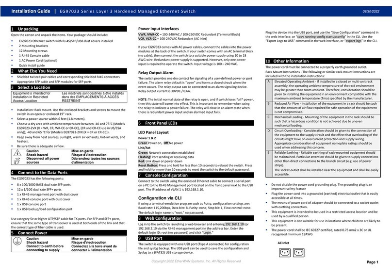
  9. EtherWAN EG97000 Series User manual

EtherWAN EG97000 Series User manual

Copyright 2019 EtherWAN Systems, Inc. Page 1
All Rights Reserved
EG97000
1/08/2019
W70G-EG97000Q2
1 Unpacking
Open the carton and unpack the items. Your package should include:
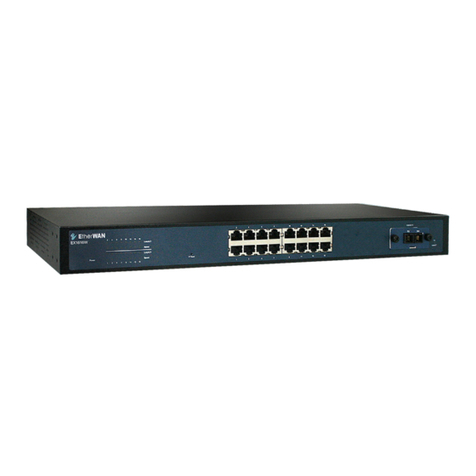
EG97000 Ethernet switch
2 Mounting brackets
12 Mounting screws
1 Console cable
1 AC Power Cord (optional)
Quick install guide
If any items are missing or damaged, notify your EtherWAN representative. If
possible, save the carton and packing material in case you need to ship or
store the switch in the future. The full product manual can be downloaded
from:
https://www.etherwan.com/support/product/EG97000-series
2 What Else You Need
Shielded twisted pair cables and corresponding shielded RJ45 connectors
Appropriate SFP cable and SFP modules for SFP ports
3 Select a Location
Installation: Rack-mount. Use the enclosed screws and brackets to mount the
switch in an open or enclosed rack.
Select a power source within 6 feet (1.8 meters).
Choose a dry area with ambient temperature between -40 and 75ºC (-40 and
167ºF).
75 °C for Models EG97244-4VZ (Z can be either WR, CR, and TR, or WR-CC,
CR-CC, and TR-CC) (CR and CR-CC use in US/CSA only);
Be sure there is adequate airflow.
4 Connect to the Data Ports
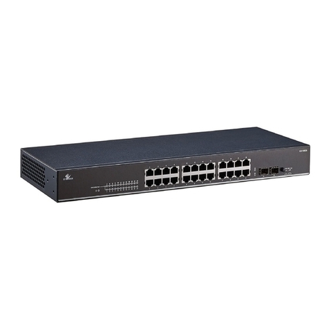
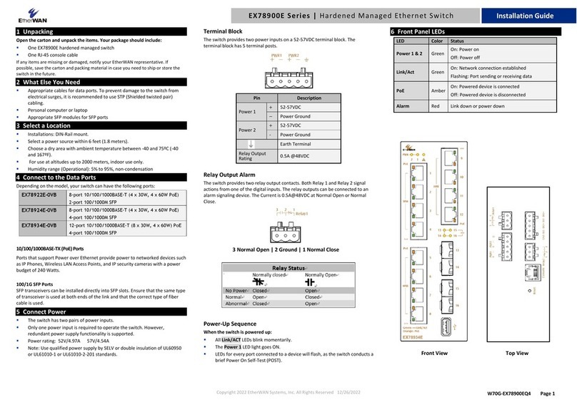
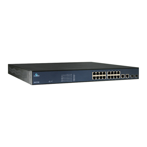
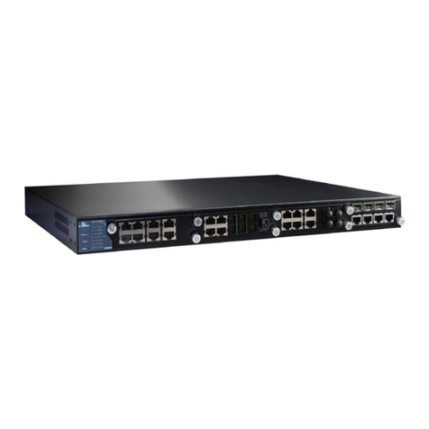
The EG97000 has the following ports:
8 x 10/100/1000 Mbps copper ports
16 x 100/1000 SFP slots
4 x 1/10G SFP+ slots
1 x RJ-45 Management port
1 x USB port
10/100/1000BASE-TX Ports
Ports 1 to 8 are gigabit copper ports and can be connected to routers, other
switches, or end devices.
100/1000BASE SFP Slots
Ports 9 –24 are 100/1000BASE SFP slots, for connection with stackable
switches to form multiple fiber interconnections. Use appropriate SFP
tranceivers.
1/10 Gbps SFP+ Slots
SFP+ ports 1 –4 are for uplink connection to core networks. Ensure that the
same type of transceiver is used at both ends of the link and that the correct
type of fiber cable is used.
5 Connect Power
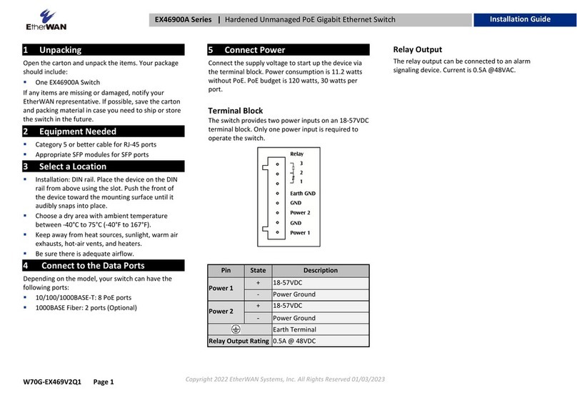
Terminal Block
If your EG97000 comes with AC power cables, connect the cables into the
power modules at the back of the switch. If your switch comes with a DC or
AC terminal block (no cable), then connect the switch to a suitable power
supply using 12 to 24 AWG wire. Redundant power supply is supported.
However, only one power input is required to operate the switch. Input
voltage is 48 VDC or 100 –240 VAC, depending on model.
Relay Output Alarm
The switch provides one dry contact for signaling of a user-defined power or
port failure. The alarm relay default is “open” and forms a closed circuit
when the event occurs. The relay output can be connected to an alarm
signaling device. Relay output current is 30VDC / 0.6A.
NOTE: The initial normal state of the relay is open, and if switch loses *all*
power, then this state will come into effect. This is important to remember
when using the relay to indicate a power failure. The relay will close in an
alarm state when there is redundant power input and an alarmed input fails.
6 Front Panel LEDs
Link/Act
Green: Network connection established
Flashing: Port sending or receiving data
Red: Link down or power down
Reset Button: Press and hold for less than 10 seconds to reboot the switch.
Press and hold for more than 10 seconds to reset the switch to the default
password.
7 Initial Configuration
Connect to the switch using the enclosed Ethernet cable to connect a serial
port on a PC to the RJ-45 Management port located on the front panel next
to the USB port. You can also use regular Ethernet cable to connect the RJ-
45 port on the PC to any of the TX ports 1 - 8. The IP address of VLAN 1 is
192.168.1.10.
Configuration via CLI
If using a terminal-emulation program such as Putty, configuration settings
are: Baud rate: 115,200bps, Data bits: 8, Parity: none, Stop bit: 1, Flow
control: none.
The default login name is “root,” no password.
Configuration via Web Browser
Log in to the switch by launching a web browser and entering 192.168.1.10 in
the address bar.
Enter the default login ID: root (no password) and click “Login.” The system
information screen will display.
8 Copy Configuration to USB
The USB port can be used to save the running switch configuration to a
(FAT32) USB storage device. Plug the device into the USB port, and use the
“Save Configuration” command in the web interface, or “copy running-config
startup-config” in the CLI.
EG97000 Series Layer 3 Hardened Managed Ethernet Switch
Installation Guide
EG97000 Layer 3 Hardened Managed Ethernet Switch
Copyright 2019 EtherWAN Systems, Inc. Page 2
All Rights Reserved
EG97000
1/08/2019
W70G-EG97000Q2
9 Other Electrical and Safety Information
(A) Elevated Operating Ambient - If installed in a closed or multi-unit rack
assembly, the operating ambient temperature of the rack environment may
be greater than room ambient. Therefore, consideration should be given to
installing the equipment in an environment compatible with the maximum
ambient temperature (Tma).
B) Mechanical Loading - Mounting of the equipment in the rack should be
such that a hazardous condition is not achieved due to uneven mechanical
loading.
C) Circuit Overloading - Consideration should be given to the connection of
the equipment to the supply circuit and the effect that overloading of the
circuits might have on overcurrent protection and supply wiring. Appropriate
consideration of equipment nameplate ratings should be used when
addressing this concern.
D) Reliable Earthing - Reliable earthing of rack-mounted equipment should
be maintained. Particular attention should be given to supply connections
other than direct connections to the branch circuit (e.g. use of power strips).
Do not disable the power cord grounding plug. The grounding plug is an
important safety feature.
Caution:
This equipment shall be used with all power supplies connected
simultaneously.
This equipment is intended to be used in a restricted access location and by
qualified personnel. This equipment is not suitable for use in locations where
children are likely to be present.
Les matériels sont destinés à être installés dans des EMPLACEMENTS À
ACCÈS RESTREINT.
This equipment must be connected to Protective earthing (PE) to AC mains
ground. The protective earthing conductor shall be minimum 18 AWG and
having green-and-yellow insulation. The thread diameter of screw type
terminal shall be minimum 3.5mm.
The ground wire should be installed first (earlier than live and neutral ires)
and then removed. The grounding wire should be longer than live and neutral
wires.
When wiring the switch to power, unscrew the two retaining screws that hold
the protective cover in place. The metal protective cover should be
reattached after the wiring is completed to avoid the danger of electric
shock.
When stripping the cable sheath for connection to the terminal block, leave
only 10mm of wires exposed for the connection.
The power cord shall be IEC 60227 certified, rated 0.75 mm2 x 3C or UL
recognized minimum 18AWG.
Terminal Block:
This product is intended to be supplied by certified DC power source and
rated output rating: 48 VDC, 1 A minimum.
AC Terminal Block
AC power rating current is 0.6A.All power connection wiring by a qualified
electrician in accordance with National Electrical Code, ANSI/NFPA 70 and
Canadian Electrical Code, Part I, CSA C22.1. An IEC certified or UL listed
single-phase type circuit-breaker, rated maximum 20A, shall be installed
between mains circuit and equipment.
Thumbscrews should be tightened with a tool after both initial installation
subsequent access to the panel.
Note:
This equipment must use UL recognized Laser Class 1 optical transceiver.
Hazardous voltages may occur within this unit when connected
to all power supplies. Prevent access to hazardous voltages by
disconnecting this equipment from all power supplies.
Plug the power cord into a grounded (earthed) electrical outlet
that is easily accessible at all times.

Other EtherWAN Switch manuals

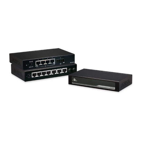
EtherWAN EX78900 Series User manual

EtherWAN

EtherWAN EX78900 Series User manual

EtherWAN EX73900 Series User manual

EtherWAN

EtherWAN EX73900 Series User manual

EtherWAN EX78600 User manual

EtherWAN

EtherWAN EX78600 User manual

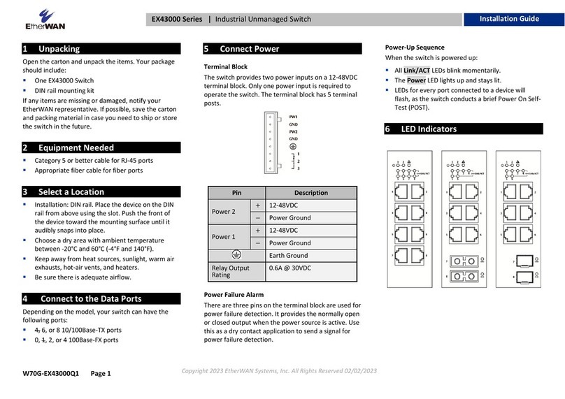
EtherWAN EX42008 Series User manual

EtherWAN

EtherWAN EX42008 Series User manual

EtherWAN EX19164 User manual

EtherWAN

EtherWAN EX19164 User manual

EtherWAN ER58000 Series User manual

EtherWAN

EtherWAN ER58000 Series User manual

EtherWAN EX32008 Series User manual

EtherWAN

EtherWAN EX32008 Series User manual

EtherWAN EX93000 User manual

EtherWAN

EtherWAN EX93000 User manual

EtherWAN EX17008A User manual

EtherWAN

EtherWAN EX17008A User manual

EtherWAN EX72000 User manual

EtherWAN

EtherWAN EX72000 User manual

EtherWAN EX32008 Series User manual

EtherWAN

EtherWAN EX32008 Series User manual

EtherWAN EX78900X Series User manual

EtherWAN

EtherWAN EX78900X Series User manual

EtherWAN EX75900 Series User manual

EtherWAN

EtherWAN EX75900 Series User manual

EtherWAN EX19162 User manual

EtherWAN

EtherWAN EX19162 User manual

EtherWAN EX38000 Series User manual

EtherWAN

EtherWAN EX38000 Series User manual

EtherWAN EX42300 series User manual

EtherWAN

EtherWAN EX42300 series User manual

EtherWAN EX78000R User manual

EtherWAN

EtherWAN EX78000R User manual

EtherWAN EX78000 Series User manual

EtherWAN

EtherWAN EX78000 Series User manual

EtherWAN EX77000 Series User manual

EtherWAN

EtherWAN EX77000 Series User manual

EtherWAN EX61000A User manual

EtherWAN

EtherWAN EX61000A User manual

EtherWAN EX75000 User manual

EtherWAN

EtherWAN EX75000 User manual

EtherWAN EX45900 series User manual

EtherWAN

EtherWAN EX45900 series User manual

EtherWAN EX41941F User manual

EtherWAN

EtherWAN EX41941F User manual

EtherWAN EX25611 User manual

EtherWAN

EtherWAN EX25611 User manual

Popular Switch manuals by other brands

Metel 200M-RS.E4 installation manual

Metel

Metel 200M-RS.E4 installation manual

Chacon DIO Rev-Shutter manual

Chacon

Chacon DIO Rev-Shutter manual

Radio Shack Switch owner's manual

Radio Shack

Radio Shack Switch owner's manual

Broadcast Tools ACS 8.2 Plus Installation and operation manual

Broadcast Tools

Broadcast Tools ACS 8.2 Plus Installation and operation manual

DiO 54715 manual

DiO

DiO 54715 manual

Sams DAS-10 User manual for use and maintenance

Sams

Sams DAS-10 User manual for use and maintenance

schmersal TQ 700 operating instructions

schmersal

schmersal TQ 700 operating instructions

Nortel 4526FX Product information

Nortel

Nortel 4526FX Product information

Cisco Nexus 9332D-GX2B Hardware installation guide

Cisco

Cisco Nexus 9332D-GX2B Hardware installation guide

Linksys SRW2008P Product data

Linksys

Linksys SRW2008P Product data

Zektor HDVI5 manual

Zektor

Zektor HDVI5 manual

Ytc YT-870 Series user manual

Ytc

Ytc YT-870 Series user manual

Perel EMS113 user manual

Perel

Perel EMS113 user manual

D-Link DGS-1250 Series reference guide

D-Link

D-Link DGS-1250 Series reference guide

Conrad Electronic PIR Switch CEI 11 operating instructions

Conrad Electronic

Conrad Electronic PIR Switch CEI 11 operating instructions

KROHNE OPTISWITCH 3100 C operating instructions

KROHNE

KROHNE OPTISWITCH 3100 C operating instructions

Trust START-LINE ACM-2300-HC Important information

Trust

Trust START-LINE ACM-2300-HC Important information

Kontron MSH8900 user guide

Kontron

Kontron MSH8900 user guide

manuals.online logo
manuals.online logoBrands
  • About & Mission
  • Contact us
  • Privacy Policy
  • Terms and Conditions

Copyright 2025 Manuals.Online. All Rights Reserved.