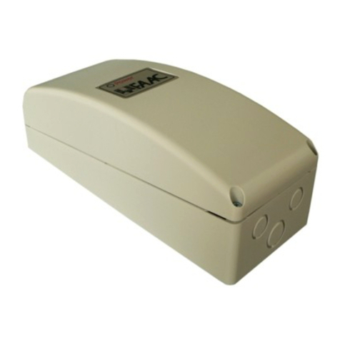
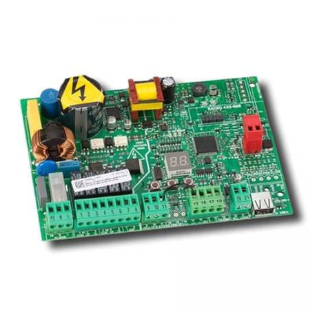
FAAC E012 User manual

E012
E012

Leggere completamente questo manuale di istruzioni prima di iniziare l’installazione del prodotto.
Il simbolo evidenzia le note importanti per la sicurezza delle persone e l’integrità dell’automazione.
Il simbolo richiama l’attenzione sulle note riguardanti le caratteristiche od il funzionamento del prodotto.
Read this instruction manual to the letter before you begin to install the product.
Symbol highlights notes that are important for people’s safety and for the good condition of the automated system.
Symbol draws your attention to the notes about the product’s characteristics or operation.
Lire ce manuel d’instructions dans son entier avant de commencer l’installation du produit.
Le symbole met en évidence les remarques pour la sécurité des personnes et le parfait état de l’automatisme.
Le symbole attire l’attention sur les remarques concernant les caractéristiques ou le fonctionnement du produit.
Vor der Installation des Produkts sind die Anweisungen vollständig zu lesen.
Mit dem Symbol sind wichtige Anmerkungen für die Sicherheit der Personen und den störungsfreien Betrieb der Auto-
mation gekennzeichnet.
Mit dem Symbol wird auf Anmerkungen zu den Eigenschaften oder dem Betrieb des Produkts verwiesen.
Lean completamente este manual de instrucciones antes de empezar la instalación del producto.
El símbolo identifica notas importantes para la seguridad de las personas y para la integridad de la automación.
El símbolo llama la atención sobre las notas relativas a las características o al funcionamiento del producto.
Lees deze instructiehandleiding helemaal door alvorens het product te installeren.
Het symbool is een aanduiding van opmerkingen die belangrijk zijn voor de veiligheid van personen en voor een goede
automatische werking.
Het symbool vestigt de aandacht op opmerkingen over de eigenschappen of de werking van het product.

Page 3
Rev. 01.2006 - Istallation Manual
EC DECLARATION OF CONFORMITY
Manufacturer : FAAC S.p.A.
Address: Via Benini, 1 - 40069 Zola Predosa BOLOGNA - ITALY
Declares that: E012 control board,
• conforms to the essential safety requirements of the following directives:
73/23/EEC and subsequent amendment 93/68/EEC.
89/336/EEC and subsequent amendment 92/31/EEC and 93/68/EEC
Additional note:
This product underwent tests in a typical uniform configuration
(all products manufactured by FAAC S.p.A.).
Bologna, 01 December 2006
The Managing Director
A. Bassi
Contents
1 INSTALLATION OF CONTROL UNIT ........................................................................................................................ 4
2 ELECTRICAL CONNECTIONS ................................................................................................................................. 5
2.1 ELECTRICAL SYSTEM LAY-OUT................................................................................................................... 5
2.2 DESCRIPTION OF CONTROL UNITS ............................................................................................................ 5
2.2.1 TECHNICAL SPECIFICATIONS ................................................................................................................................................ 5
2.2.2 PRESENTATION OF THE BOARD ............................................................................................................................................. 6
2.2.3 POWER SUPPLY CONNECTION .............................................................................................................................................. 7
2.3 ELECTRICAL WIRING FOR BOARD AND MOTORS .................................................................................... 8
2.3.1 AN ESSENTIAL CONTROL ..................................................................................................................................................... 10
2.4 WIRING OF (OPTIONAL) ACCESSORIES ................................................................................................. 10
2.4.1 CONNECTION OF (OPTIONAL) BATTERIES ......................................................................................................................... 11
2.5 PROGRAMMING ...................................................................................................................................... 12
2.5.1 PROGRAMMING THE OPERATING PARAMETERS .............................................................................................................. 12
2.5.2 ELECTRONIC CLUTCH .......................................................................................................................................................... 12
2.5.3 PROGRAMMING OPENING, CLOSING TIMES AND GATE PAUSE .................................................................................... 13
2.5.4 OPERATING LOGICS ............................................................................................................................................................ 14

Page 4
Rev. 01.2006 - Istallation Manual
A
B
C
1 INSTALLATION OF CONTROL UNIT
Procedure for securing components in the water-tight enclosure:
1- Secure the transformer to the water-tight enclosure in position (A)
2- If you are using buffer batteries (optionals), secure the relevant support in position (B).
3- Insert the batteries in the support.
4- Secure the control unit in position (C) with the 4 self-tapping screws (supplied), placing the supplied
spacers between the control unit and the relevant support.
5- Secure the board support to the enclosure, using the supplied screws.
Using the four diam.6 plastic expansion plugs and relevant securing screws (not supplied), install the
enclosure of the unit (to which all the accessories and pulse generators will then be connected), on the side
of the gate supplied with 230V current (which must be connected to the toroidal transformer to change it
to 13V) and near to the operator.
Route the electrical cables in the lower part of the enclosure, using adequate rigid tubes and/or hoses and
appropriate connections.
Leave the cables inside the enclosure lengthy enough to enable you to wire up.
Secure two water-tight (IP 55) pull-boxes (not
supplied), one for each operator, for wiring
up.
Use 12-terminal wiring bars (not supplied).
According to the mains voltage, the voltage coming out of the transformer
can differ from the value given in paragraph 2.2.1. Before putting the
control unit into service, we recommend you to check if the voltage
coming out of the transformer is between 12Vac and 14.5 Vac.This value
is to be checked with load-free transformer, i.e. with the transformer
powered but disconnected from the board.

Page 5
Rev. 01.2006 - Istallation Manual
B
C
D
F
E
B
FA
2 ELECTRICAL CONNECTIONS
2.1 ELECTRICAL SYSTEM LAY-OUT
A) Control board enclosure
B) Pull boxes (not supplied)
C) 3x1.5 mm²(2+T) 230V
D) Key-operated selector switch
OPTIONAL
E) Flashing lamp 12 volt
OPTIONAL
F) Infrared photocells OPTIONAL
Notes:
1) To lay the electrical cables,
use adequate rigid and/or
flexible sheaths.
2) The figure shows an example
of connection to the
DOMOLINK operator. This
connection layout can be
used also for DOMOSWING.
2.2 DESCRIPTION OF CONTROL UNITS
2.2.1 TECHNICAL SPECIFICATIONS
SINGLE MULTI-FUNCTION CONTROL BOARD
Power supply voltage
of the toroidal transformer: 230V - 50/60Hz
Power supply voltage
of the control unit: 13V - 50/60Hz
Absorbed power: 7 W
Motor max. load: 50 W (per motor)
Accessories max. load 12 Vdc 150mA
Flashing light max. load: 12 Vdc 21W max.
Operating temperature: -20°C / +55°C
Protective fuse: 2
Function logics: Automatic/
Step-by-step
automatic /
Step-by-step
semiautomatic.
Programming of functions: By Dip-Switch.
Work time: Self-learning during programming.
Pause time: Self-learning during programming.
Leaf closing delay: Two preset levels.
Adjustment of motor force: Two preset levels.
Specifications of toroidal transformer 230V~: Primary 230V~ / sec.13V~ / 150VA
Slow-downs: At opening and closing during self-learning.
Clutch device: Electronic clutch adjustable on two preset levels.

Page 6
Rev. 01.2006 - Istallation Manual
2.2.2 PRESENTATION OF THE BOARD
DESCRIPTION OF TERMINALS
TERMINAL BOARD CN1(power supply)
Terminals “1-2” (VAC-VAC): Connect, to these terminals, the secondary winding wires arriving from the
toroidal transformer. Power ON is indicated by the lighting up of LED DL1 "power".
Terminals “3-4” (+BAT-BAT): Connect the 2 optional batteries to these terminals. During normal operation,
the control unit keeps the batteries charged. The batteries come into operation when the transformer does
not supply power.
During connection, respect the polarity indicated on the board.
A maximum of two batteries, connected in parallel, can be connected to the control unit.
Power supply provided by the batteries should be considered an emergency situation.
The number of possible manoeuvres depends on the quality of the batteries, the gate's structure
(weight, dimensions, condition of the pivot , etc…), and on the time since power was cut, etc, etc.
Terminals “5-6” (+OUT-OUT): Output for 12Vdc power supply to the accessories.
The maximum load of the accessories must not exceed 150mA.
Terminal “ ”: Connect the earthing cable to this terminal. The earthing cable must be connected to the
earthing system of the 230V~ power supply line.
The connection is absolutely necessary for correct operation of the control unit.
TERMINAL BOARD CN2 (motors)
Terminals “7-8” (OPM1-CLM1): The motor power cable must be connected to these terminals. For two-
motor installations, the power cable of the motor which opens first must be connected to these terminals.
Terminals “9-10” (OPM2-CLM2): The power cable of the motor opening second must be connected to these
terminals. For one motor only installation, no device must be connected to these terminals.
Terminals “11-12” (COM1-EL-S): (optional) The electric lock, if any, with 12 Vdc / 15W max power supply,
must be connected to these terminals.
For 2-leaf installations, the electric lock must always be fitted on the leaf of motor M1, the one which opens
first.
Terminals “12-13” (COM1-LAMP): Connect, to these terminals, the flashing light with power supply of
12Vdc 21W max. Before every manoeuvre, the flashing light pre-flashes for 0.5 sec.
Use a steady light flashing lamp; flashing is controlled by the control unit.
We advise you to install the flashing lamp before programming, because it indicates its phases.
TERMINAL-BOARD CN3 (commands and safety devices)

Page 7
Rev. 01.2006 - Istallation Manual
Terminals “14-18” (OPEN A-COM1): Normally open contact.Connect, to these terminals,any pulse generator
(e.g.push-button, key selector,etc..) which, by closing a contact,generates a pulse for totally opening or
closing the gate. The operation of this input is defined by dip-switch 3 - see paragraph 2.5.1.
Terminals “15-18” (OPEN B-COM1): Normally open contact. Connect, to these terminals, any pulse generator
(e.g. push-button, key selector, etc..) which, by closing a contact, generates a pulse for partially opening
the gate.
In two-motor installations (Dip-switch 5=ON); partial opening corresponds to the total opening of the leaf
on which the motor M1 is installed.
In single-motor applications (Dip-switch 5=OFF), partial opening coincides with an opening of about ~80%
of the total memory-stored opening.
If a total opening command (OPEN A) is given during the partial opening stage, the control unit memory
stores the command, which is executed when partial opening has finished.
Terminals “16-18” (FSW-COM1): Normally closed contact. Connect, to these terminals, any safety device
(photocell, pressure switch, safety edge etc..) which, by opening a contact, affects the gate's closing
motion, reversing it to the mechanical opening stop, without disabling automatic re-closure if it is enabled.
The status of this input is signalled by LED "FSW".
This contact can be disabled with dip-switch 6 - see paragraph 2.5.1.
If you decide to disable the photocells, you do not have to jumper the input.
The control unit is supplied with the photocell input disabled.
Terminals “17-18” (STOP-COM1): Normally closed contact. Connect, to these terminals, any pulse generator
(push-button, key selector, etc..) which, by opening a contact, immediately stops the gate and disables all
automatic functions. The status of this input is signalled by the "STOP"LED. The gate resumes its memory-
stored cycle only by means of another total or partial opening pulse.
This contact can be disabled with dip-switch 7 - see paragraph 2.5.1.
If you decide to disable the stop command, you do not have to jumper the input.
The control unit is supplied with the stop command input disabled.
TERMINAL BOARD CN4
5-terminal connector for coupling receiver.
DIP-SWITCH
DP1(SW1): Parameter adjustment, see paragraph 2.5.1.
FUSES
F1: 16A T 250V 5X20.
F2: 10A T 250V 5X20.
LEDS ON OFF
POWER: Control unit fed by transformer No power supplied, or control unit fed by
batteries.
FSW: Safety device disengaged or input disabled. Safety device engaged, contact open.
STOP: Command inactive or input disabled. Command active, contact open.
Indicated in bold: status of LEDs with the gate closed, and control unit fed by transformer.
2.2.3 POWER SUPPLY CONNECTION
As concerns power supply:
1Use a 3 x 15 mm2 cable for conveying the 230V mains current, protected by a fuse or by a 10 Amp
circuit breaker, routing from the dwelling to the gate.
Page 8
Rev. 01.2006 - Istallation Manual
C
F
A
E
D
D
E
B
2.3 ELECTRICAL WIRING FOR BOARD AND MOTORS
1ST CASE: LEFT LEAF OPENS FIRST TOWARD THE INSIDE
A) 230 Volt Mains power supply coming from the electrical panel of the dwelling.
Protected by a differential switch or by a 10 Amp fuse.
3 x 1.5 mm2line from the dwelling to the pilaster
B) The terminal with fuse, inserted in the enclosure, is used for connecting the 230 V~ mains supply to the
primary winding of the toroidal transformer.
For the connection, respect the indications in the figure.
C) 12 Vdc power supply from toroidal transformer.
D) BROWN
E) BLUE
F) YELLOW/GREEN
BROWN
BLUE
BROWN
BLUE
RED RED YELLOW/GREEN
BROWN
BLUE BROWN
BLUE
The figure shows an example of
connection to the DOMOLINK
operator. This connection layout
can be used also for
DOMOSWING.

Page 9
Rev. 01.2006 - Istallation Manual
F
E
D
C
B
A
D
E
BROWN
BLUE
BROWN
BLUE
RED RED YELLOW/GREEN
BROWN
BLUE
BROWN
BLUE
The figure shows an example of
connection to the DOMOLINK
operator. This connection layout
can be used also for
DOMOSWING.
2nd CASE: RIGHT LEAF OPENS FIRST TOWARD THE INSIDE
A) 230 Volt Mains power supply coming from the electrical panel of the dwelling.
Protected by a differential switch or by a 10 Amp fuse.
3 x 1.5 mm2line from the dwelling to the pilaster
B) The terminal with fuse, inserted in the enclosure, is used for connecting the 230 V~ mains supply to the
primary winding of the toroidal transformer.
For the connection, respect the indications in the figure.
C) 12 Vdc power supply from toroidal transformer.
D) BROWN
E) BLUE
F) YELLOW/GREEN

Page 10
Rev. 01.2006 - Istallation Manual
2.3.1 AN ESSENTIAL CONTROL
If you are not using safety devices (photocell, pressure switch, edge, etc..) or pulse generators (push-
button, key selector,etc..), make sure that cursors 6 and 7 on the dip-switch are disabled (position "ON").
If you decide to disable these commands, you do not have to jumper the input.
This control is essential, otherwise the motor will not start.
IMPORTANT: The dip-switch cursors are shown in white in the following drawings.
2.4 WIRING OF (OPTIONAL) ACCESSORIES
BATTERIES
TOROIDAL TRANSFORMER
POWER SUPPLY TO EXTERNAL
ACCESSORIES
EARTH
MOTOR 1
MOTOR 2
ELECTRIC LOCK 12V
FLASHING LAMP
COURTESY LIGHT
RECEIVER
OTHER CLOSING
SAFETY DEVICES
5-PIN RECEIVERS
CONNECTOR
MAX 1 PAIR FSW

Page 11
Rev. 01.2006 - Istallation Manual
2.4.1 CONNECTION OF (OPTIONAL) BATTERIES
Terminals "+ BAT - BAT". Connect the 2 optional batteries to terminals "+ BAT - BAT".
During normal operation, the control unit keeps the batteries charged.
The batteries come into operation when the transformer does not supply power.
During connection, respect the polarity indicated on the board.
A maximum of two 12 Vdc - 1.2 Ah batteries, connected in parallel, can be connected to the control unit.
Power supply provided by the batteries should be considered an emergency situation.
The number of possible manoeuvres depends on the quality of the batteries, the gate's structure
(weight, dimensions, condition of the pivot , etc..), and on the time since power was cut, etc.
BROWN
BLUE
BLUE
BROWN
RED
RED
After installing the
batteries, open the
pre-perforated
section in the lower
part of the enclosure.

Page 12
Rev. 01.2006 - Istallation Manual
2.5 PROGRAMMING
2.5.1 PROGRAMMING THE OPERATING PARAMETERS
The multi-function control board has a dip-switch (DP1) for programming the operating parameters.
Dip-switch DP1 is used for setting various parameters, such as the operating logic, automatic closing, and
enabling/disabling the safety devices, etc..
All selectable parameters are shown in the table below.
To avoid compromising the condition and operation of the control unit, parameters must be set with the
control unit powered down.
We advise you to select the parameters you require before programming.
2.5.2 ELECTRONIC CLUTCH
This control unit has an electronic clutch device based on the control of the current absorbed by each motor.
This device is very important for the purpose of safety.
It is active during both closing and opening. When it operates, it reverses gate movement without disabling
automatic closing if enabled.
If it operates for two consecutive times, the control unit goes into "STOP" status, disabling all automatic
functions. This is because, when the clutch operates twice consecutively, it means that the obstacle is still
present and it could be dangerous to perform any other manoeuvre. When the obstacle has been removed,
give a "START" pulse and the control unit will resume the memory-stored cycle.
If the clutch operates three consecutive times, and for more than 120 seconds, the control unit performs an
"EMERGENCY" procedure: i.e. it executes opening until the opening mechanical stop is reached, and
then closes, if automatic closing has been enabled. In this way the control unit synchronises itself
automatically, and automatically re-calculates the opening and closing stop points.
The "EMERGENCY" procedure occurs while the motors are turning at low speed.
DIP-SWITCH FUNCTION ON OFF
1
2
3
4
5
6
7
8
Electronic clutch
Automatic closing
Total opening function
Leaf closing delay
Number of motors
Photocells input
Stop input
Programming
Max. force / Min. sensitivity
Enabled
Opens - Stop - Closes - Stop
3-sec. delay
Two-motor operation
Disabled
Disabled
During programming
Min. force / Max. sensitivity
Disabled
Opens- Closes (without Stop)
1.5 sec. delay
Single motor operation
Enabled
Enabled
Normal operation

Page 13
Rev. 01.2006 - Istallation Manual
2.5.3 PROGRAMMING OPENING, CLOSING TIMES AND GATE PAUSE
During this stage, the control unit memory stores work time and any pause time.
To access programming, follow the instructions below:
1- Release the operators (see the instructions on the mechanical operators) and take the leaves to about
halfway of the opening travel.
2- Relock the operators (see the instructions on the mechanical operators) and power up the system.
3- Turn ON dip-switch 8 on the control unit. The flashing lamp lights up on steady beam to indicate entry
to the programming procedure.
4- Give a total opening pulse with the "START" push-button or with the radio control (if already memory
stored) and the leaves will begin to move.
The first manoeuvre the control unit carries out is closing.
5- Make sure that both leaves perform the closing manoeuvre and that the leaf with motor M2 moves
first.
If this does not happen, stop gate movement with a "RESET" pulse, jumper connecting the two
"RESET" pins to each other and using the connector (see figure).
6- Cut the power supply and take the connector back to its normal position (see figure).
7- Make the suitable corrections to the motor connections, and repeat from point 4, changing over the
cables of the motors on connector CN2 (see paragraph 2.3.).
8- When they reach the closing mechanical stop point, the leaves pause for two seconds, and then begin
the opening stage
9- When both leaves reach the opening mechanical stop point, the pause time count begins.
10- When the required pause time has elapsed, give a total opening pulse.
The leaves begin the closing stage.
11- When the leaves reach the closing stop, programming has finished.
12- Turn OFF dip-switch 8 - the flashing lamp goes OFF to finish programming.
NORMAL RESET
RESET
CONNECTOR

Page 14
Rev. 01.2006 - Istallation Manual
2.5.4 OPERATING LOGICS
(1) The operation described in the tables is obtained if the STOP input is enabled (dip-switch 6 = OFF).
When the input is disabled, the command has no effect.
(2) The operation described in the tables is obtained if the input of the photocells is enabled (dip-switch 7
= OFF). When the input is disabled, the command has no effect.
(3) In single motor installations, partial opening of the gate corresponds to about 60% of the memory
stored opening. In two-motor installations, partial opening corresponds to the total opening of the leaf
on which motor M1 is installed.
AUTOMATIC LOGIC (DIP-SWITCH 2=ON / DIP-SWITCH 3=OFF
GATE STATUS PULSES
Closed
Open in pause
Closing
Opening
OPEN A
Opens leaves and re-
closes after pause time
Closes at once
Reverses gate movement
No effect
OPEN B
Partially opens the gate (3)
Closes at once
No effect
No effect
STOP (1)
Disables OPEN commands
Stops pause time count
Stops operation
Stops operation
PHOTOCELLS
(2)
No effect
Stops operation and on
release, if pause time
exceeded, closes after 5
sec
Reverses motion
No effect
STEP-BY-STEP AUTOMATIC LOGIC (DIP-SWITCH 2=ON / DIP-SWITCH 3=ON
GATE STATUS PULSES
Closed
Open in pause
Closing
Opening
OPEN A
Opens leaves and re-
closes after pause time
Closes at once
Stops gate motion and,
at next pulse, opens
Stops gate motion and,
at next pulse, closes
OPEN B
Partially opens the gate (3)
Closes at once
No effect
No effect
STOP (1)
Disables OPEN commands
Stops pause time count
Stops operation
Stops operation
PHOTOCELLS
(2)
No effect
Stops operation and on
release, if pause time
exceeded, closes after 5
sec.
Reverses motion
No effect
SEMIAUTOMATIC LOGIC (DIP-SWITCH 2=OFF / DIP-SWITCH 3=OFF
GATE STATUS PULSES
Closed
Open
Closing
Opening
OPEN A
Opens leaves
Closes at once
Reverses gate movement
OPEN B
Partially opens the gate (3)
Closes at once
No effect
No effect
STOP (1)
Disables OPEN commands
Stops operation
Stops operation
Stops operation
PHOTOCELLS
(2)
No effect
On release, closes after 5
sec.
Reverses motion
No effect
SEMIAUTOMATIC STEP-BY-STEP LOGIC (DIP-SWITCH 2=OFF / DIP-SWITCH 3=ON
GATE STATUS PULSES
Closed
Open
Closing
Opening
OPEN A
Opens leaves
Closes at once
Stops gate movement
and, at next pulse, opens
Stops gate movement
and, at next pulse,
closes
OPEN B
Partially opens the gate (3)
Closes at once
No effect
No effect
STOP (1)
Disables OPEN commands
Stops operation
Stops operation
Stops operation
PHOTOCELLS
(2)
No effect
On release, closes after 5
sec.
Reverses motion
No effect


Le descrizioni e le illustrazioni del presente manuale non sono impegnative. La FAAC si riserva il diritto, lasciando inal-
terate le caratteristiche essenziali dell’apparecchiatura, di apportare in qualunque momento e senza impegnarsi
ad aggiornare la presente pubblicazione, le modifiche che essa ritiene convenienti per miglioramenti tecnici o per
qualsiasi altra esigenza di carattere costruttivo o commerciale.
The descriptions and illustrations contained in the present manual are not binding. FAAC reserves the right, whilst
leaving the main features of the equipments unaltered, to undertake any modifications it holds necessary for either
technical or commercial reasons, at any time and without revising the present publication.
Les descriptions et les illustrations du présent manuel sont fournies à titre indicatif. FAAC se réserve le droit d’apporter à
tout moment les modifications qu’elle jugera utiles sur ce produit tout en conservant les caractéristiques essentielles,
sans devoir pour autant mettre à jour cette publication.
Die Beschreibungen und Abbildungen in vorliegendem Handbuch sind unverbindlich. FAAC behält sich das Recht
vor, ohne die wesentlichen Eigenschaften dieses Gerätes zu verändern und ohne Verbindlichkeiten in Bezug auf die
Neufassung der vorliegenden Anleitungen, technisch bzw. konstruktiv/kommerziell bedingte Verbesserungen vorzu-
nehmen.
Las descripciones y las ilustraciones de este manual no comportan compromiso alguno. FAAC se reserva el derecho,
dejando inmutadas las características esenciales de los aparatos, de aportar, en cualquier momento y sin compro-
meterse a poner al día la presente publicación, todas las modificaciones que considere oportunas para el perfec-
cionamiento técnico o para cualquier otro tipo de exigencia de carácter constructivo o comercial.
De beschrijvingen in deze handleiding zijn niet bindend. FAAC behoudt zich het recht voor op elk willekeurig moment de
veranderingen aan te brengen die het bedrijf nuttig acht met het oog op technische verbeteringen of alle mogelijke
andere productie- of commerciële eisen, waarbij de fundamentele eigenschappen van de apparaat gehandhaafd
blijven, zonder zich daardoor te verplichten deze publicatie bij te werken.
FAAC S.p.A.
Via Benini, 1
40069 Zola Predosa (BO) - ITALIA
Tel. 0039.051.61724 - Fax. 0039.051.758518
www.faac.it
www.faacgroup.com
732954 - Rev. B
Table of contents
Other FAAC Control System manuals
Popular Control System manuals by other brands

Mitsubishi Heavy Industries
Mitsubishi Heavy Industries SC-SL4-AE2 Technical manual

SABROE
SABROE UNISAB S-Control instruction manual

Grunbeck
Grunbeck GENO-CPR-tronic 02 family Operation manual

eqss
eqss OverWatch 6253 installation manual

Endress+Hauser
Endress+Hauser Smart System for Surface Water SSP100B operating instructions

Sutter Instrument
Sutter Instrument Lambda 10-2 Operation manuals