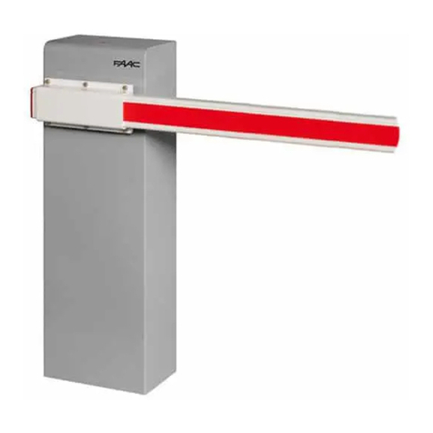
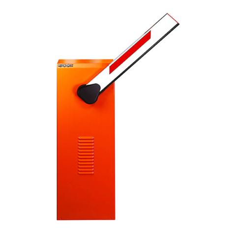
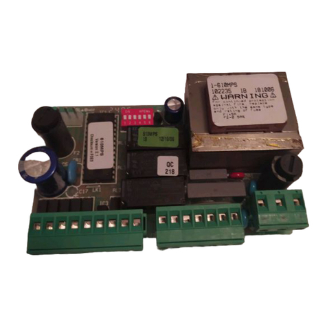
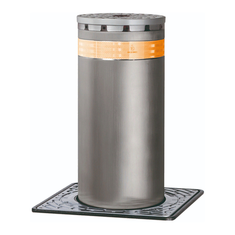
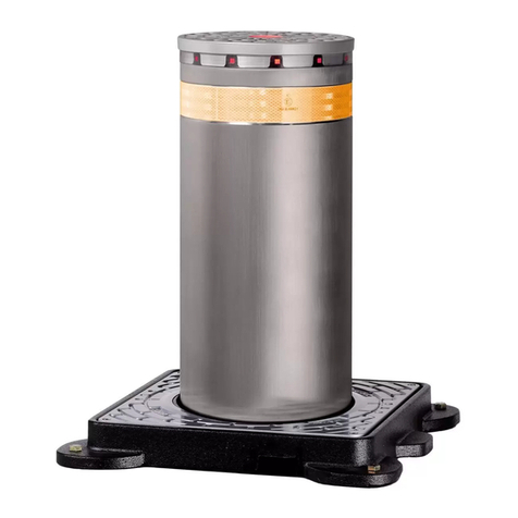
FAAC 620 STANDARD User manual

FAAC International, Inc.
303 Lexington Avenue
Cheyenne, WY 82007
www.faacusa.com
January, 2007
620/640 Operator And
624BLD Control Panel
Installation Manual
CONTENTS
THE 620/640 BARRIER GATE
OPERATOR AND 624BLD
CONTROL PANEL INSTALLATION
MANUAL:
The 624 BLD Control Panel 22
General Description 22
Technical Specifications 23
Terminal Strip Layout 24
Connecting Photo Beams 24
Typical Jumpers Diagram 24
Connecting Main
Power Switch
25
Programming 27
1st Level Programming 27
2nd Level Programming 29
Master/Slave Wiring 32
Programming Notes 29
Led Diagnostics 30
Maintenance 32
Safety in Gate Design 33
Troubleshooting 34
Limited Warranty 36
The 624 BLD Control Panel Installation Instructions
Important Safety Information 2
Technical Data 4
Unpacking The Barrier 5
General Characteristics 5
Manual Release Mechanism 7
Prepare The Forms For Concrete 9
Attach The Barrier Beam 11
Check The Positive Stops 11
Balancing The Beam 11
Emergency Bypass Solenoid
Anti Vandalism Valve
12
Changing The Length Or Type Of Beam 13
Beam And Beam Accessories 14
620 Cabinet Exploded View 16
620 Motor/Pump Exploded View 17
640 Cabinet Exploded View 13
640 Motor/Pump Exploded View 13
Determine The Orientation
OF the Installation
8
Adjusting The Pressures 12
Break Away Beam Stop Switch 15

Both the installer and the owner and/or operator of this
system need to read and understand this installation
manual and the safety instructions supplied with other
components of the gate system. This information
should be retained by the owner and/or operator of the
gate.
WARNING! To reduce the risk of injury or death
1. READ AND FOLLOW ALL
INSTRUCTIONS.
2. Never let children operate or play with gate
controls. Keep the remote control away from
children.
3. Always keep people and objects away from
the gate. NO ONE SHOULD CROSS THE
PATH OF THE MOVING GATE.
4. Test the gate operator monthly. The gate
MUST reverse on contact with a rigid object
or stop when an object activates the non-
contact sensors. After adjusting the force or
the limit of travel, retest the gate operator.
Failure to adjust and retest the gate operator
properly can increase the risk of injury or
death.
5. Use the emergency release only when the
gate is not moving.
6. KEEP GATES PROPERLY MAINTAINED. Read
the owner’s manual. Have a qualified service
person make repairs to gate hardware.
7. The entrance is for vehicles only. Pedestrians
must use separate entrance.
8. SAVE THESE INSTRUCTIONS.
When installing the photo-beams with this unit two
things need to be considered.
1. Care should be exercised to reduce the risk of
nuisance tripping, such as when a vehicle, trips
the sensor while the gate is in motion.
2. One or more photo-beams shall be located
where the risk of entrapment exists, such as
the perimeter reachable by the moving gate.
GATE DESIGN
1. A gate is a potential traffic hazard, so it is im-
portant that you locate the gate far enough away
from the road to eliminate the potential of traffic
getting backed up. This distance is affected by the
size of the gate, how often it is used, and how fast
the gate operates.
2. The operator you choose to install on your gate
must be designed for the type and size of your
gate and for the frequency with which you use the
operator.
3. Your gate must be properly installed and must
work freely in both directions before the automatic
operator is installed.
4. An automatic operator should be installed on the
inside of the property/fence line. Do not install the
operator on the public side of the property/fence
line.
5. Pedestrians should not use a vehicular gate system.
Prevent such inappropriate use by installing
separate gates for pedestrians.
6. Exposed, reachable pinch points on a gate are
potentially hazardous and must be eliminated or
guarded.
7. Outward swinging gates with automatic operators
should not open into a public area.
8. The operating controls for an automatic gate must
be secured to prevent the unauthorized use of those
controls.
9. The controls for an automatic gate should be
located far enough from the gate so that a user
cannot accidentally touch the gate when operating
the controls.
10. An automatic gate operator should not be installed
on a gate if people can reach or extend their arms
or legs through the gate. Such gates should be
guarded or screened to prevent such access.
INSTALLATION
1. If you have any question about the safety of the
gate operating system, do not install this operator.
Consult the operator manufacturer.
2. The condition of the gate structure itself directly
affects the reliability and safety of the gate
operator.
3. Only qualified personnel should install this
equipment. Failure to meet this requirement could
cause severe injury and/or death, for which the
manufacturer cannot be held responsible.
4. The installer must provide a main power switch that
meets all applicable safety regulations.
5. Clearly indicate on the gate with the 2 warning signs
that are included (visible from either side of the
gate).
6. It is extremely unsafe to compensate for a damaged
gate by increasing hydraulic pressure.
7. Devices such as photo beams must be installed to
provide better protection for personal property and
pedestrians. Install reversing devices that are
appropriate to the gate design and gate application.
8. Before applying electrical power, be sure that the
voltage requirements of the equipment correspond
to your supply voltage. Refer to the label on your
operator system.
IMPORTANT SAFETY INFORMATION
January, 2007
620/640 Operator And
624BLD Control Panel Installation Manual
Page 2

January, 2007
620/640 Operator And
624BLD Control Panel Installation Manual
Model Duty Cycle Typical Use
Class I: Residential Vehicular Gate Operator
402 750
422 760
412 400
620 640
885
Limited duty
• Home use
• Small apartment building, for
example, up to 4 units in a
building, with limited public
access
Class II: Commercial/General Access Vehicular Gate Operator
400 640
620 885 Continuous duty • Apartment buildings
• Very public access
Class III: Industrial/Limited Access Vehicular Gate Operator
400 640
620 885 Continuous duty • No public access
Class IV: Restricted Access Vehicular Gate Operator
620 640
885 Continuous duty • Prison rated security
U.L. CLASS AND FAAC OPERATOR
USE
1. Use this equipment only in the capacity for which it
was designed. Any use other than that stated should
be considered improper and therefore dangerous.
2. When using any electrical equipment, observe some
fundamental rules:
• Do not touch the equipment with damp or
humid hands or feet.
• Do not install or operate the equipment
with bare feet.
• Do not allow small children or incapable
persons to use the equipment.
3. If a gate system component malfunctions, turn off
the main power before making any attempt to repair
it.
4. Do not attempt to impede the movement of the
gate. You may injure yourself as a result.
5. This equipment may reach high temperatures
during operation; therefore, use caution when
touching the external housing of the operator.
6. Learn to use the manual release mechanism
according to the procedures found in this in-
stallation manual.
7. Before carrying out any cleaning or maintenance
operations, disconnect the equipment from the
electrical supply.
8. To guarantee the efficiency of this equipment, the
manufacturer recommends that qualified personnel
periodically check and maintain the equipment.
Page 3

Page 4
January, 2007
620/640 Operator And
624BLD Control Panel Installation Manual
TECHNICAL DATA
THE 620/640BARRIER GATE OPERATOR(S)
Parameter 620 640
Express
Available beam length, ft (m) 8 (2.5) 10 (3) 13 (4) 16 (5) 20 (6)
10 (3) 13 (4) 16 (5) 18 (5.5) 23 (7)
13 (4) 16 (5) 20 (6)
Maximum beam length, ft
(m)1
Wood
Aluminum
13 (4)
12 (3)
16 (5)
13 (4)
16 (5)
16 (5)
18 (5.5)
20 (6)
20 (6)
23 (7)
Articulated beam
(aluminum only) 10 (3) 13 (4) NA NA NA
Skirted beam
(aluminum only) NA NA 16 (5)
20 (6) 23 (7)
Pump capacity, liters 2 1.5 2 1.5 1
Motor speed, rpm 280021400
Opening time, sec (not
including braking) 2 3 4
5.5 8
Motor run time2 (frequency of
use), % 100 100
Power voltage required, VAC
(frequency, Hz)3230/115 +6 or -10% (50–60)3
Power consumption, W 440
Operator cabinet weight, lb
(kg) 161 (73) 185 (84)
Operator cabinet dimensions,
in. (cm)
6-5/8 ´ 13-3/4 ´ 42-1/2
(17 ´ 35 ´ 108)
7-7/8 ´ 14-15/16 ´ 42-1/2
(20 ´ 38 ´ 108)
Type of oil Lubrication Engineers- MONOLEC 6115
Oil quantity, qt (l) 2.1 (2)
Fan Standard Standard
Automatic fan operation
temperature, deg F (deg C) 113 (45) 113 (45)
Automatic motor shut off
temperature, deg F (deg C) 185 (85) 185 (85)
Thermal overload switch, deg
F (deg C) 212 (100)
1 Measurements in feet are rounded; measurements in meters are precise.
2 The model 620 115VAC is not available with a 2800 rpm motor.
3 Your standard 220 VAC/115VAC power source meets the specification for 230 VAC, +6 or -10%

Page 5
January, 2007
620/640 Operator And
624BLD Control Panel Installation Manual
UNPACKING THE BARRIER
When you receive your Barrier System, complete the
following steps.
Before you remove the barrier beam or cabinet from its
shipping carton, inspect the carton for damage. As you
unpack the carton, insure that all the parts listed below for
your system are included and are undamaged.
Inspect the parts for damage. Notify the carrier immediately
if you note any damage because the carrier must witness the
damage before you can file a claim.
The U.L. listed Model 620 or 640 Barrier gate system
includes a barrier beam and a cabinet housing the hydraulic
operator and control panel.
The main differences between the 620 and the 640 Barrier
systems are in the length of the barrier beam and in the
speed of operation. The 620 system controls beams that are
6-1/2 to 13 ft (2 to 4.5 m) in length and offers extremely
fast opening and closing times. The 620 is ideal for single-
lane vehicular traffic in moderate to heavy traffic. The 620
Barrier can also be articulated (jointed) for use with low
overhead clearances or skirted to prevent vehicles from
passing beneath the beam.
The 640 Barrier system is for barrier beams that are 13 to
23 ft (4 to 7 m) long and is suitable for wide entrances and
heavy-duty applications. The 640 Barrier can also be skirted
(Aluminum Beams Only).
The barrier beam is attached to a heavy-duty, lockable metal
cabinet bolted to a cement foundation. Inside the cabinet
are the operator and the control panel. Important metal
parts of the barrier unit have been powder coated to resist
the effects of rust and smog.
The motor housing holds the oil that drives the pistons and
helps to cool the motor. The temperature of the oil is
monitored, and in high oil temperatures a cooling fan
automatically turns on for further cooling.
The hydraulic motor of either the 620 or 640 operator
drives two single-acting pistons. Both are attached to the
rocker arm, and the rocker arm rotates the barrier beam. A
compression spring attached to one piston serves to
counterbalance the beam, and an adjustable braking feature
guarantees smooth movement of the beam through its
travel and prevents damage to the beam and cabinet from
abrupt stopping.
Some notable features enhance the reliable and safe
operation of the 620 or 640 Barrier. First, a hydraulic
locking device holds the beam in both the opened and
closed positions. Second, the metal cabinet that
houses the operator can be opened only with a key.
Third, the barrier includes a Manual Release function
to disengage the beam from its hydraulic operation
so that you can raise or lower the beam by hand.
Fourth, two adjustable hydraulic valves precisely
control the force of the beam in the opening and
closing directions.
An optional solenoid valve is available for
automatically disengaging the hydraulic system in the
event of power failures.
Both the 620 and 640 Barriers are supplied with the
FAAC 625 BLD Control Panel. The control panel allows
you to select the following:
• Logical mode of operation
• Braking time of the beam
• Pause time between opening and closing
The control panel also provides terminal connections
for a number of other reversing and gate system
accessories.
Furthermore, the control panel provides a number of
light-emitting diodes (LEDs) and a digital display for
easily diagnosing any operational problems.
GENERAL CHARACTERISTICS
The Parts List
Operator Carton:
1 Operator cabinet
1 Key for cabinet
Bolts for attaching beam to cabinet: 4 or 6,
depending on the barrier and type of beam
Beam Carton (optional):
1 barrier beam

Page 6
January, 2007
620/640 Operator And
624BLD Control Panel Installation Manual
1 Aluminum Beam 15 Pressure Adjusting Screw 29 Right Side Piston
2 Left Hand Stop 16 Pressure Adjusting Screw 30 Spring Support (large spring
groove)
3 Rocker Assembly 17 Cabinet 31 Spring Support Ring
4 Right Hand Limit Adjuster 18 Hole for conduit/wire 32 Spring
5 Left Hand Limit Adjuster 19 Anchor Bolt 33 Right Side Piston Bleed Screw
6 Rocker Arm 20 Foundation Plate (Optional) 34 Thermal (On Older Models)
7 Left Side Limit Switch 21 Hole for conduit/wire 35 Right Side Limit Switch
8 Oil Fill Cap 22 Grounding Lug 36 Spring Adjuster Nut
9 Vent Screw 23 Conduit (Not Supplied) 37 Right Hand Stop
10 Cooling Fins (On motor/pump 24 Control Panel Enclosure 38 Lock
11 Left Side Piston Bleed Screw 25 Hydraulic Hose 39 Door
12 Left side Piston 26 Manual Release 40 Screen For Air Intake
13 Motor Pump Assembly 27 Spring Support (small spring 41 Cooling Fan
14 Hydraulic Hose 28 Screen Cover for Air Intake
Figure 1. The interior of the 620/640 Barrier cabinet (for right-hand orientation)

Page 7
January, 2007
620/640 Operator And
624BLD Control Panel Installation Manual
WARNING! You must have the manual release
key to access the function of the manual release.
Using any other tools could damage the manual
release mechanism.
The Manual Release function for the 620 or 640 Barrier
is engaged with a key in the operator cabinet on the
lower right side. (See figure 2)
Using the Manual Release key to disengage the beam
from hydraulic operation allows you to operate the
barrier by hand.
You disconnect the hydraulic operation of the beam by
turning the Manual Release key counterclockwise. Then
you can raise or lower the barrier by hand.
Manual operation of the beam is important during the
installation process and can be useful during power
interruptions or power failures.
To re-engage the hydraulic operation of the barrier,
turn the key clockwise until the mechanism is “snug”
tight.
MANUAL
(UNLOCK)
AUTOMATIC
(LOCK)
MANUAL RELEASE MECHANISM
Figure 2. Manual Release Location on both the 620/640 Barrier

Page 8
January, 2007
620/640 Operator And
624BLD Control Panel Installation Manual
WARNING! Do not install the barrier in such a
way that the beam moves within 2 feet (610
mm) of a rigid object.
Installing the 620 or 640 Barrier System consists of the
following general steps:
• Determining the orientation of the installation
• Preparing the forms for the concrete mounting
slab and conduit
• Mounting the cabinet on the concrete slab
• Connecting the main power source to the
operator
• Wiring the control panel for operational logic
• Wiring additional accessories into the control
panel
• Decreasing the hydraulic pressures
• Programming the control panel
• Attaching the barrier beam
• Testing the operation of the beam
Note: The following installation instructions
assume you are fully capable of installing an
electronic barrier gate. This manual does not
instruct you in designing a gate, pouring the
cement foundation, or basic electrical wiring. The
installation tasks discussed in this manual are
tasks peculiar to the 620 and 640 Barriers.
DETERMINE THE ORIENTATION OF THE INSTALLATION
You first need to determine whether your operator is set
up for a right-hand or left-hand installation (see Figure 3).
Open the panel door of the operator cabinet with the key
provided and lift the door up and away from the cabinet,
taking care not to disconnect the cabling to the fan. Look
at the two pistons to see which has the compression
spring surrounding it. Compare your operator with Figure
3 and use the figure to help you determine the orientation
of your installation.
If your operator is not in the correct orientation, turning
the cabinet around 180 deg is the easiest way to solve the
problem. We suggest you call us if your installation site
cannot accommodate this solution since the orientation of
the barrier can be changed with about an hour’s worth of
work.
NOTE: It make no difference if the
hoses are crossed or not.
Beam side Beam
Cabinet
Panel
side Compression
spring
Compression
spring
Panel
side
Cabinet
Beam Beam side
(a) Right-hand orientation: top view and hose connections
(b) Left-hand orientation: top view and hose connections
INSTALLING THE BARRIER
Figure 3. Right Hand vs. Left Hand Installation of the 620/640 Barrier

Page 9
January, 2007
620/640 Operator And
624BLD Control Panel Installation Manual
PREPARE THE FORMS FOR THE CONCRETE SLAB AND
CONDUIT
You need to set the concrete forms to provide a cement
footing that is a minimum of 18 by 18 in. (46 by 46 cm)
and that is poured a minimum of 18 in. (46 cm) below
the ground level or just below the frost line, whichever
is greater (see Figure 4). (Your soil conditions will also
affect the size of the cement footing.) To help prevent
rust, the top of your cement footing should be above
ground level.
Within the form boundaries you must locate the
electrical conduit so that it will protrude through the
foundation plate (the plate is provided as an option) and
above the top of the foundation plate about
1/2 in. (1.3 cm).
The exact placement of the conduit is determined partly
by the foundation plate you use and more importantly
by the access holes in the bottom of the operator
cabinet (see Figure 5). If you choose to supply your own
foundation plate, be sure to use steel that is 3/8 in. (1
cm) thick for the plate and be sure to provide a hole
large enough to accommodate your two electrical
conduits, one for high-voltage wire and one for low-
voltage wire. In addition, your foundation plate needs
four 1/2-in. (1-1/4 cm) anchor bolts that extend at least
6-1/2 in. (16-1/2 cm) into the cement footing. The
anchor bolts should be positioned to match the holes in
the bottom of your operator's cabinet.
1/4”
24”
15”
18”
After the concrete is poured in the forms and before it
sets, place the foundation plate in the cement so that the
top of the plate is level and flush with the top of the
cement.
Allow the concrete to set a minimum of two full days
before you mount the operator cabinet.
With the key provided, open the operator's panel door
and lift the door away from the cabinet. It may be
necessary on your model of operator to disconnect the
wiring to the fan on the panel door to allow you to more
easily handle the heavy cabinet.
Set the operator cabinet on the foundation plate, aligning
the holes in the bottom of the cabinet with the bolts and
conduit protruding above the foundation plate. Bolt the
cabinet to the foundation plate and cement footing. If
necessary, reconnect the wiring to the fan on the panel
door.
Before connecting the main power to your barrier, you
must remove the vent screw on the hydraulic power pack.
Midway along the top, left edge of the hydraulic power
pack is a 3 mm Allen screw. Remove it now. Failure to
remove the screw can result in erratic operation of the
barrier beam. Do not throw the screw away in case you
ever need to transport the barrier unit or its hydraulic
power pack.
Figure 4. Recommended Concrete Form Dimensions

Page 10
January, 2007
620/640 Operator And
624BLD Control Panel Installation Manual
B
D
C
A
E
Depth:
s
:
n
.
Old Style New Style
620 Dimensions 620 Dimensions
A(rectangle): 12 1/16 x 2 1/16 in.
Between bolts
B: 11 1/2 in.
C: 3 1/2 in.
Edge to edge
D: 6 in.
E: 13 3/4 in.
A (rectangle): 13 3/8 x 3 1/8 in.
Between bolts
B: 12 1/2 in.
C: 5 1/8 in.
Edge to edge
D: 9 in.
E: 15 1/4 in.
640 Dimensions 640 Dimensions
FG
H
J
Entire plate, edge to edge:
14 1/16 x 7 7/8 in.
Hole diameter: 2 1/4 in.
Distance fromhole to edge:
F: 2 3/4 in.
G: 1 1/4 in.
H: 2 3/4 in.
J: 10 5/8 in.
Entire plate, edge to edge:
15 1/4 x 9 1/16 in.
Hole diameter: 2 1/4 in.
Distance from hole to edge:
F: 3 1/2 in.
G: 1 1/4 in.
H: 3 1/2 in.
J: 12 in.
American Style Italian Style
Figure 7. Positive Stop Location and Adjusters
Figure 5. FAAC foundation Plates for the 620/640 Barrier
Vent Screw
Location
Oil Fill with Built in
Dipstick
Figure 6. Oil Fill and Vent Screw Locations

Page 11
January, 2007
620/640 Operator And
624BLD Control Panel Installation Manual
CHECK THE COMPRESSION SPRING
The compression spring should be adjusted so that it
holds the beam in any position that it is placed while in
manual mode. (Manual mode is discussed on page 7
shown in Fig. 2)
Move the beam by hand to a half-opened position. The
beam should stay there when you remove your hand.
Note: All compression spring adjustments should
be made with the beam in the vertical (open)
position.
If the beam drifts toward the closed position, turn the
adjuster nut (shown in Fig. 10) clockwise to tighten the
compression spring.
If the beam drifts toward the opened position, turn the
adjuster nut (shown in Fig. 10) counterclockwise to
loosen the compression spring.
.
Note: Proper adjustment of the spring will
counterbalance the beam. This will allow the
minimal pressure setting necessary to move the
beam in a smooth movement.
NOTE: The spanner wrench shown in figure 10
is NOT sold by FAAC or needed top make this
adjustment.
ATTACH THE BARRIER BEAM
WARNING! Do not install the barrier in such a way
that the beam moves within 2 feet (610 mm) of a
rigid object.
Before you attach the barrier beam, be sure you have
disconnected the barrier from hydraulic operation by
means of the Manual Release mechanism (turning the
key counterclockwise).
Next you attach the beam to the operator cabinet with
the beam in a vertical position. See Figure 8 if you are
attaching an aluminum beam to a model 620
operator ,see Figure 9 if you are attaching an aluminum
beam to a model 640 operator. (Wooden beams require
additional sandwich plates).
CHECK THE MECHANICAL STOPS
First, be sure the hydraulic operation of the beam is still
disengaged (the Manual Release key should be turned
counterclockwise). Next, move the beam by hand from
the fully opened position (vertical) to the fully closed
position (horizontal) and back to the fully opened
position. If the positions are not perfectly vertical and
perfectly horizontal, then adjust the mechanical stops
as necessary (see Figure 7) using a 17mm socket
wrench. The jam nut must be loosened first and
tightened last.
615/620
Figure 8. Beam Attachment 620 (Aluminum Beam)
Figure 9. Beam Attachment 640 (Aluminum Beam)
Figure 10. Adjuster Nut
640

Page 12
January, 2007
620/640 Operator And
624BLD Control Panel Installation Manual
ADJUST THE HYDRAULIC PRESSURES
Now that the beam is attached, re-engage the hydraulic
operation of the barrier by rotating the Manual Release
key clockwise.
Send an opening activating signal to the barrier. The
signal should open the barrier. If it does not open,
increase the pressure of the opening bypass valve (the
green valve) by turning the screw clockwise in small,
1/8- turn increments until the beam does open.
Test the closing of the barrier in the same way. If the
beam fails to move in the closing direction, then
increase the pressure of the closing bypass valve (the
red valve) by turning the screw clockwise in small
increments until the beam does close.
Remember that you should set the bypass pressure
valves so that the beam works with the least pressure
necessary. It is a safety feature of the barrier that the
beam should apply no more than about 33 lb (15 kg)
force against any obstacle it might encounter.
WARNING! For maximum safety to people and
property, use photo eyes and other non-contact
reversing devices in addition to adjusting the
bypass pressure valves to the minimum settings.
INSTALLING THE EMERGENCY BYPASS SOLENOID
AND ANTI-VANDALISM VALVE (230VAC MODELS
ONLY)
WARNING! Turn the main power off before you
make any electrical connections or set any
switches inside the control panel box.
The emergency bypass solenoid automatically
disengages the hydraulic system of the barrier beam
when the main power is not available. This allows the
barrier to be raised by hand so that people and vehicles
can safely pass during power interruptions and failures
without having to manual release the barrier.
Note: Once the emergency bypass solenoid has
disengaged the hydraulic system and once you
have raised the beam by hand, you cannot lower
the barrier beam until the power is restored or
by using the manual release key.
If you are installing the optional emergency bypass
solenoid, you must first turn off the main power and
disengage the hydraulic system by using the Manual
Release key.
Then you disassemble the hydraulic lines between the
pistons and the operator so that you can install new
hydraulic pipe fittings.
After installing the new pipe fittings, install the
emergency bypass solenoid as shown in figure ()
After connecting the solenoid, you need to connect the
hydraulic lines between the operator and the pistons.
How you connect the lines depends on the orientation
of your barrier installation (see Figure 11).
Finally, connect the solenoid to your main power line
so that it can sense when power is or is not available
(see Figure 11).
Re-engage the hydraulic system with the Manual
Release key so that you can test the installed solenoid.
To test the solenoid, turn off the power to the barrier. If
the solenoid works, you should be able to raise the
beam but not lower it after raising it. You should be
able to lower the beam only after turning the power
back on.
Install the anti-vandalism
valve with the instructions
that are provided with it in
it’s packaging.
Figure 11. Emergency By-Pass Valve
and the Anti-Vandalism Valve

Page 13
January, 2007
620/640 Operator And
624BLD Control Panel Installation Manual
Rigid Beams: Part Numbers of Compression Springs for Various Lengths
Beam and Required
Spring 620 Barrier Systems 640 Barrier Systems
Redwood Beam, ft 8–10 12–14 16 NA 16–18 18–20 20 NA
Rigid Aluminum
Beam, ft (m) 6 (2) 8 (2 1/2) 10 (3) 13 (4) 13 (4) 16 (5) 20 (6) 23 (7)
FAAC Part No. for
Compression Spring 7210855 7210695 7210705 7210885 7210735 7210745 7210755 7210805
Beam and Required
Spring 620 Barrier Systems 640 Barrier Systems
Skirted Aluminum
Beam, ft (m) 6 (2) 8 (2 1/2) 10 (3) 13 (4) 13 (4) 16 (5) 20 (6) 23 (7)
FAAC Part No. for
Compression Spring 7210695 7210715 7210735 7210745 7210795 7210805 7210815 7210825
Skirted Beams: Part Numbers of Compression Springs for Various Lengths
Unbolt the piston with the compression spring from the
rocker arm. Then very carefully unscrew the cap holding
the compression spring by hand to the left to remove
the spring from the piston. Remove the spring from the
piston.
NOTE: Hold the bottom of the piston cylinder to
keep the piston rod from sliding out of the
cylinder.
Install the correct compression spring by placing it over
the piston and screwing it into place with adjusting cap.
Then bolt the piston to the rocker arm and reinstall the
steel cross member. Re-engage the hydraulics by
turning the Manual Release key clockwise.
Be sure to recheck the tension of the compression
spring before you turn on the main power to the
operator. Then be sure to adjust the hydraulic
pressures.
CHANGING THE LENGTH OR TYPE OF BARRIER
BEAM
WARNING! Do not install the barrier in such a
way that the beam moves within 2 feet (610 mm)
of a rigid object.
Changing the length or type of the beam requires
installing a different balancing compression spring.
Make sure you have the correct compression spring
(designed for a particular weight of beam).
The installer is responsible for making sure that the
compression spring is the correct spring for the barrier
beam.
The following tables show which springs are designed
for various beam types and lengths. To check for the
part number of the compression spring in your barrier,
check the tag attached to the spring previously
installed.
If it is necessary for you to replace the spring in a
cabinet with another compression spring, do the
following. First, turn off the main power to the operator
and then open the cabinet panel. Turn the Manual
Release key counterclockwise. Then move the beam by
hand to the fully opened position.

Page 14
January, 2007
620/640 Operator And
624BLD Control Panel Installation Manual
BEAM AND BEAM ACCESSORIES
Assembled Beam Skirt Kit
Recommend aluminum beams only
Steps 1-5 for assembly of
Beam Skirt Kit
Figure 13. Articulated beams
ideal for low ceiling heights.
Figure 14. Round Beams
(620 Models Only)
Figure 15. Break Away
Round Beams
(620 Models Only)
Figure 12. Skirted Beam Kit and Assembly Instructions.
(The Skirt Kits Are Intended For Aluminum Beams Only)

Page 15
January, 2007
620/640 Operator And
624BLD Control Panel Installation Manual
23/4”
23/4”
12”
12”
BREAK AWAY BEAM “STOP” SWITCH
Figure 16. 620 Break Away Round Beam Stop Switch Installation Instruc-

Page 16
January, 2007
620/640 Operator And
624BLD Control Panel Installation Manual
POS. PART DESCRIPTION QTY
1 N/A FAAC Logo 1
2 N/A 620 Cross Member 2
3 N/A Cross Member Bolt 2
4 N/A Lock Washer (10MM) 8
5 N/A Screen/Filter 1
6* 2022711 624 BLD Control Panel 1
7 416004 620 Cabinet (Orange) 1
8 N/A Washer (4MM) 4
9 N/A Nut (4MM) 16
10 N/A Nut (10MM) 2
11 N/A Positive Stop Bolt
(10x35MM)
2
12 499460 Rocker Assembly Housing 1
13 N/A Door Gasket 94”
14 2484 Bearing (Output Shaft) 2
15 N/A Output Shaft 1
16 7073015 Ball Joint 2
17 415001 Rocker Arm 1
18 7580145 Limit Switches 2
19 N/A Screw (3x16MM) 4
20 N/A Bolt (Allen Head 4X10MM) 4
21 N/A Limit Switch Cams 2
POS. PART
NUMBER
DESCRIPTION QTY
22 N/A Limit Switch Cam Plate 1
23 N/A Lock Washer (6MM) 2
24 N/A Screw (6x10MM) 2
25 N/A Spacer 2
26 N/A Bolt 4
27 N/A Harness (Limit Switches) 1
28 7291025 Lock Dog 1
29 7120505 Key Cylinder 1
30 7131005 Viro Key 10
31 N/A Screen/Filter 1
32 7270645 Cabinet Door 1
33 N/A Wire Loom 9
34 N/A Bolt (10x140MM) 2
35 N/A Cable Clamp 1
36 N/A Harness (Fan) 1
37** N/A Cooling Fan 1
38 N/A Bolt (Allen Head 4x16MM) 2
39 N/A Fan Guard 1
40 N/A Skin Pack 1
620 CABINET EXPLODED VIEW
*624 BLD Control Panel 115VAC = 2022712
** Electric Fan 115VAC = 727316

Page 17
January, 2007
620/640 Operator And
624BLD Control Panel Installation Manual
640 CABINET EXPLODED VIEW
POS. PART
NUMBER
DESCRIPTION QTY
1 N/A FAAC Logo 1
2 N/A 620 Cross Member 2
3 N/A Cross Member Bolt 2
4 N/A Lock Washer (10MM) 8
5 N/A Screen/Filter 1
6* 2022711 624 BLD Control Panel 1
7 416004 620 Cabinet (Orange) 1
8 N/A Washer (4MM) 8
9 N/A Nut (4MM) 18
10 N/A Nut (10MM) 2
11 N/A Positive Stop Bolt
(10x35MM)
2
12 499460 Rocker Assembly Housing 1
13 N/A Door Gasket 102”
14 2484 Bearing (Output Shaft) 2
15 N/A Output Shaft 1
16 7073015 Ball Joint 2
17 416003 Rocker Arm 1
18 7580145 Limit Switches 2
19 N/A Screw (3x16MM) 4
20 N/A Bolt (Allen Head 4x10MM)) 4
21 N/A Limit Switch Cams 2
POS. PART
NUMBER
DESCRIPTION QTY
22 N/A Limit Switch Cam Plate 1
23 N/A Lock Washer (6MM) 2
24 N/A Screw (6x10MM) 2
25 N/A Spacer 2
26 N/A Bolt (10x20MM) 4
27 N/A Harness (Limit Switches) 1
28 7291025 Lock Dog 1
29 7120505 Key Cylinder 1
30 7131005 Viro Key 10
31 N/A Screen/Filter 1
32 7270655 Cabinet Door 1
33 N/A Wire Loom 9
34 N/A Bolt (10x140MM) 2
35 N/A Cable Clamp 1
36 N/A Harness (Fan) 1
37** N/A Cooling Fan 1
38 N/A Bolt (Allen Head 4x16MM) 2
39 N/A Fan Guard 1
40 N/A Skin Pack 1
*624 BLD Control Panel 115VAC = 2022712
** Electric Fan 115VAC = 727316

Page 18
January, 2007
620/640 Operator And
624BLD Control Panel Installation Manual
620 MOTOR PUMP ASSEMBLY
EXPLODED VIEW

Page 19
January, 2007
620/640 Operator And
624BLD Control Panel Installation Manual
POS PART
NUMBER
DESCRIPTION QTY
101 7221005 Spring Adjustment Fork 1
102 7182155 Shoulder Bolt 4
103 7049145 Spring Adj. Retainer 1
105 7360165 Cylinder Protection Guide 1
106 7222725 Spring Support Ring 1
107 2487 Snap Ring (Spring Support) 1
108 7039285 Washer 8
109 7110115 Banjo Bolt 4
110 N/A Lock Washer 2
111 2274 Screw (Air Bleed) 2
112 N/A Copper Washer 2
113 725202 Piston (Spring Side) 1
114 7073015 Ball Joint 2
115 N/A Harness (Thermal) 1
116 7543005 Temperature Switch 1
117 7361275 Hydraulic Hose 2
118 7039275 Fiber Washer 1
119 7099315 Gasket (Flange) 2
120 7112055 Oil Cap (Dip Stick) 1
121 7043355 O-Ring (Strain Relief) 1
122 N/A Strain Relief 1
123 N/A Screw 4
124 N/A Washer 4
125 7220625 Mounting Bracket 2
126 7099245 Gasket (Strain Relief) 1
127 7270535 Flange (Top) 1
128 2274 Vent Screw 1
129 7094065 Washer 1
130 7230295 Tie Rod 4
131 N/A Star Washer 4
132 N/A Operator Body 1
133 7514075 Power Cord 1
134 N/A Screw 1
135 2365 Bolt (Motor) 4
POS PART
NUMBER
DESCRIPTION QTY
136 N/A Washer 4
137 702003 Nut (Jam) 4
138* 7700205 Motor 1
139** 3204435 Lobe Pump* 1
140 N/A Fork (Non Spring Cylinder) 1
141 725203 Piston (Non Spring Side) 1
142 N/A Pin (Pump) 2
143 7090010015 O-Ring (Pump to Valve Body) 2
144 4404065 Inlet Valve 2
145 7049005 Retainer 2
146 7090300015 O-Ring (Shuttle Piston) 1
147 4180285 Shuttle Piston 1
148 4404085 Lock Valve 2
149 7049005 Retainer (Brass) 2
150 4997645 Valve Body 1
151 N/A Roll Pin (Manual Release Lock) 1
152 N/A Bolt (Allen Head) 2
153 N/A By Pass Valve Feet 2
154 N/A By Pass Valve Spring 2
155 4180395 By Pass Screw 1
156 4180395 By Pass Screw 1
157 7090150015 O-Ring ( By Pass Screws) 2
158 N/A O-Ring (Manual Release) 1
159 4180305 Manual Release 1
160 7090050015 O-Ring (Inlet Valve) 6
161 N/A Roll Pin (Manual Release Rod) 1
162 N/A Coupler (Manual Release Rod) 1
163 7128035 Manual Release Knob
(Triangular)
1
164 424593 Manual Release Assembly 1
165 N/A Wiper Seal 2
166 N/A O-Rings (Cylinder Top) 2
167 7090360025 O-Ring (Piston Center) 2
168 N/A O-Ring (Cylinder Center) 2
169 6115* Artic Grade Oil (Quarts) 2
170 2170* Seal Kit 1

Page 20
January, 2007
620/640 Operator And
624BLD Control Panel Installation Manual
640 MOTOR PUMP ASSEMBLY
EXPLODED VIEW
Other manuals for 620 STANDARD
6
This manual suits for next models
2
Table of contents
Other FAAC Control System manuals
Popular Control System manuals by other brands

Hunter
Hunter ACC2 Assembly instructions

Compool
Compool Pool-Spa Control System Time Master installation instructions

LOGICDATA
LOGICDATA DMIclassic Series operating manual

Topcon
Topcon NORAC UC4.5 installation manual

Waterway
Waterway NEO 2100 instruction manual

Fagerhult
Fagerhult SE - 566 80 Habo quick start guide

Lofa
Lofa MC704 Operation and Troubleshooting

Siemens
Siemens RRV852 operating instructions

GSK
GSK GSK983Ta-H Connection manual

Progressive Industries
Progressive Industries EMS-LCHW30 Operating and installation guide

RF SOLUTIONS
RF SOLUTIONS ELITE-RXL manual

eqss
eqss OverWatch Sinoboom RD-RT Series installation manual