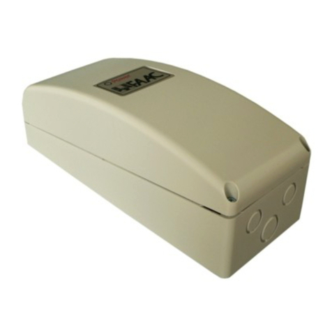
FAAC Jcall Operator's manual

532178 – Rev.A
Jcall quick installation guide
GSM system for the remote operation and management of access automation systems
1. Introduction
Jcall is an access control system that uses a simple ring from a mobile phone. Enabled users (whose phone number has already
been entered in the system) can operate the Jcall controlled automated access system by a ring from their mobile phone,
without charge.
The system allows you to specify different access permissions by organising users into groups. Each group is associated with a
contact to be activated, daily time bands, months of the year, expiry date and the enable flag. The system records all the
accesses and events for the last thirty days in its permanent memory.
2. Package contents
The installation kit includes (see Figure 1):
a. Jcall board
b. High-gain GSM antenna with magnetic base
c. Network power supply
d. Plate and screws for installation in a Model E enclosure (available as an
accessory)
The installation kit does not include:
The USB cable for connecting the Jcall board to the PC.
The GSM SIM to place on the board.
WARNING: it is recommended to purchase a rechargeable GSM SIM card from the mobile phone network operator that offers
the best coverage in the area in which the system is installed. The mobile phone network operator must provide 2G GSM
coverage. SIM cards from operators that provide only 3G or 4G coverage are not compatible. If you use JCALL with
programming via the Internet, it is recommended to use a SIM card with an unlimited calls and data plan.
The following accessories are recommended (please contact your local FAAC sales representative for availability and prices):
Expansion card to increase the number of relay outputs
FAAC “Model E” enclosure
3. Jcall board description
The Jcall board is shown in Figure 2. The following components are indicated:
a. Power supply connector 12V
b. Digital inputs connector
c. Peripherals power supply connector (see the
characteristics of the devices that can be connected)
d. Relay output connectors (see the characteristics of the
devices that can be controlled)
e. “Operational LED” (green)
f. “Error/initialisation LED” (red)
g. Hard reset button, to restore factory settings
h. GSM SIM housing
i. Expansion card connector
j. Mini USB type B connector for connection to PC
k. GSM antenna connector
l. “GSM network registration LED” (blue)
m. “Power on LED” (white)
n. On/off button
o. Mounting holes
Figure 2: JCALL board description
Figure 1: package contents

4. Installation requirements
The requirements for the proper installation of the Jcall system are:
•If installed outdoors, the board should be housed in a suitable enclosure to protect it from moisture, water, dust and heat.
For this purpose, Jcall can be installed in the “Model E” enclosure, which is available as an accessory, using the metal plate
and screws provided with the installation kit.
•Installation in a zone with no GSM coverage. If the GSM signal is weak or the signal is received from multiple GSM cells at
the same time, at certain moments the controller may not be reachable. If these conditions persist after checking the
coverage, it is recommended that you change the phone network operator that supplied the SIM card.
•The availability of a GSM SIM card (of an operator that provides 2G GSM network coverage) that has had the PIN
protection disabled.
Jcall also allows the access system to which it is connected to be operated remotely: which is why the installation must be
carried out in compliance with current safety standards.
5. Installation procedure
To install the kit, follow the steps below:
1. Before inserting the GSM SIM card on the board, make sure that it has been activated by making a call of a few seconds
using a mobile phone. The PIN of the GSM SIM card also needs to be disabled before it is inserted in the board. If
necessary, contact your SIM retailer.
2. Insert the GSM SIM card into its housing. The gold coloured contacts of the SIM card should be facing downwards.
3. Connect the GSM antenna. The antenna must be placed in an area covered by the GSM service: avoid placing it in
closed metal containers or inspection chambers.
4. Connect the output terminals to the electrical circuit to be activated as described in section 6. Make sure that the
characteristics of the circuit to be activated are compatible with the specifications of the relays.
5. Plug in the power connector. You may need to wait up to 2 minutes after power has been turned on to the board before
the system is fully functional. The board is operational when the operational LED is lit (see e Figure 2).
6. Check the “GSM network registration” LED (lFigure 2): when the board is correctly connected to the GSM network, the
LED flashes briefly every 4 seconds. If it does not, make sure that:
a. The SIM card has been inserted properly in its housing
b. The SIM card has been activated and its PIN has been disabled
c. The antenna has been properly connected and that there is GSM coverage
7. Send an SMS containing the text “MASTER” to the GSM SIM card number: Jcall will record the number of the sender as
a number authorised for programming via SMS. A welcome SMS will be received as confirmation.
WARNING: The number enabled for programming can be changed only through a card reset (via SMS or a hard reset) or via
the Jcall Manager software.
8. Enter the users that are enabled to open the entrance via SMS (see section 9) or via the Jcall Manager software.
9. The Jcall system can be activated by simply sending a ring from one of the enabled numbers. The Jcall board will
activate the opening contact and operate the access system only if the caller number is listed among those authorised.
WARNING: To activate Jcall, the caller’s number must be visible to the receiver. If a registered user has enabled the “hide
number” option on his phone, when calling, he must enter *31# before the number of the Jcall SIM card e.g. *31#3471234XXX.
WARNING: When entering a landline number in Jcall that is connected to a switchboard, make sure that you enter (via SMS or
the Jcall Manager software) the telephone number as it actually appears from outside the switchboard.
6. Connecting Relays
The Jcall board has 2 electromechanical relay outputs (OUT1 and OUT2) to operate up to 2 accesses that can be connected via
the connectors shown in point d Figure 2. Each output allows you to connect the automation system contact in a normally open
"NO" or normally closed "NC" position, depending on the type of automation system to be connected. The maximum voltage and
current rating of the relay outputs are shown in section 12.
WARNING: The wide coverage of the GSM network means that the caller can operate the accesses connected to the Jcall from
anywhere, provided that he/she is enabled to do so. When the system is installed, presence detectors can be installed in order to
ensure proximity of the user to the entrance.
WARNING: By adding an expansion card, available as an accessory, a single Jcall board can manage up to 10 relay outputs (so
up to 10 entrances can be controlled by a single board).

7. Status of the LEDs
The LEDs shown at points e, f, l and m in Figure 2 indicate the operating status of the device. Their function is summarised in the
following table.
LED Colour Status
Operational LED (e) Green - Steady on: device operating correctly
- Off: device off or in error status
Error/Initialisation LED (f) Red - Steady on: device in error status or in initialisation phase (in this case the
operational LED will also be lit)
- Off: device working correctly
GSM signal LED (l) Blue - Flashing (10ms On, 1s Off): call in progress
- Flashing (10ms On, 2s Off): data connection in progress
- Flashing (10ms On, 4s Off): device registered on GSM network, no call or
connection in progress
- Flashing (500ms On, 500ms Off): device is being registered on the GSM
network, no SIM, SIM not working or PIN not disabled.
- Off: device off
Power supply LED (m) White - Steady on: power on
- Off: no power
8. Button functions
The function of the buttons shown in points g and n of Figure 2 are indicated in the following table.
Button name
Function Usage
Hard Reset button (g) - Short press: no action
- Prolonged press (longer than 5s): resets the device to the factory settings
(cancels all settings and programmed data)
On/Off button (n) - Short press: turns the device on or off
9. Programming via SMS
Programming Jcall via SMS allows users to be entered and deleted and some commands to be sent via SMS. The telephone
numbers enabled for programming Jcall via SMS are one of the options that can be set from the PC using the Jcall Manager
software. The phone number of the sender of the SMS containing the text “MASTER” that was sent during installation is
automatically entered in the list of numbers authorised for programming via SMS.
Jcall processes upper case and lower case letters in the same way. The commands available via SMS are shown in the following
table. COMMANDS RESTRICTED TO PROGRAMMERS SYNTAX
Enter a user in the default group.
Note: If the phone numbers do not include the country code, Jcall
automatically adds the country code for the country in which it is located. If
you do not wish to add the country code, place the letter "p" before the
number.
ADD 3281234XXX (add country code)
or
ADD +393281234XXX
or
ADD p4567 (do not add country code)
Enter more than one enabled user in the default group (maximum of 12
users per SMS) ADD 3281234XXX 3471234XXX 3331234XXX
Enter users in the “friends” group (maximum of 12 users per SMS). Note:
The “friends” group must already have been entered in Jcall via the Jcall
Manager software.
ADD friends 3281234XXX 3471234XXX
3331234XXX
Delete users. Use the letter “p” to delete the numbers entered without a
country code. REMOVE 3281234XXX 3471234XXX
3331234XXX
Activate relay "N". The value of "N" must be between 0 and 1 (with an
expansion card it can be between 0 and 9). SWITCH ON N (example SWITCH ON 0)
Deactivate relay "N". The value of "N" must be between 0 and 1 (with an
expansion card it can be between 0 and 9). SWITCH OFF N (example SWITCH OFF 0)
Timed activation of relay "N". The value of "N" must be between 0 and 1
(with an expansion card it can be between 0 and 9). The duration of the
activation can be configured via the Jcall Manager software. OPEN N
Update the time and date of the board DATE
Restart the board RESTART
Deactivate Jcall. If this command is used, even authorised users will be
unable to operate the access system.
Note: The board will revert to normal operation after it is restarted or after
it receives the ACTIVATE command.
BLOCK
Jcall reactivation request, following the BLOCK command ACTIVATE
Reset the board (all the settings will be reset and the phone number list will
be deleted).
Note: The PUK code is supplied with the card.
RESET !!! PUK
Disable send SMS to the master number (SMS programming reply or
information SMS from the operator). SMS OFF
Enable send SMS to the master number (SMS programming reply or
information SMS from the operator).
This is the default setting.
SMS ON

CONTROL FUNCTIONS RESERVED FOR NORMAL USERS SYNTAX
Timed activation of the output associated with the group to which he/she
belongs. OPEN
WARNING: the relay codes 0-9 to use in the SMS commands or in programming using the Jcall Manager software correspond to
terminals OUT1-OUT10 on the board according to the following table:
Relay code Board terminal
0 OUT1
1 OUT2
2 OUT3
3 OUT4
4 OUT5
5 OUT6
6 OUT7
7 OUT8
8 OUT9
9 OUT10
10. Programming using the Jcall Manager management software
The Jcall Manager software allows Jcall to be programmed entirely via a PC and can be downloaded from the download area at
the following web address: http://jcallwebmanager.faacgroup.com
Jcall Manager allows you to:
•enter, delete and modify users
•enter, delete and modify groups of users (e.g. time bands enabled for access)
•modify the settings of the Jcall board
•display the access log
•access the board diagnostics functions
To program the board, it must be connected to the PC using a Mini USB type B cable (not included).
11. Programming via the Internet: Jcall WebManager
The Jcall WebManager platform allows the Jcall control unit to be programmed and monitored remotely via the Internet using the
GPRS connection without the need for cables.
For further information on the Jcall WebManager platform, please contact your local FAAC sales representative.
12. Technical data
Jcall board
Operating temperature from -30°C to +70°C
Power supply 12V DC
Average current consumption minimum: 90 mA, maximum: 300 mA
Output port for programming and monitoring via PC Mini-USB type B serial port
Number of main board inputs/outputs 4 digital inputs, 2 relay outputs
Maximum number of outputs using the expansion card Up to 10 relay outputs
Frequency band Quad-band GSM 850/900/1800/1900MHz
Board dimensions 136 mm x 108 mm x 30 mm
Board weight, approx. 100g
maximum OUT terminal voltage 24 VAC/VDC
maximum OUT terminal current 1 A
Peripheral power supply voltages available 5V, 12V
Maximum available peripheral power supply current 240mA@12V, 500mA@5V
Power supply
Input voltage 88-264VAC / 47-63Hz
Input current 400mA@230VAC
Output voltage 12V DC
Output current 2.1 A
Use Internal
Power supply type Stabilised switching
Power supply dimensions 78x51x28 mm
Power supply weight, approx. 200g
GSM Antenna
Connector SMA, UFL
SMA antenna cable length 3m
SMA antenna fastening Magnetic
SMA antenna height 7 cm
For further information, please see the download area at http://jcallwebmanager.faacgroup.com and/or contact your local FAAC
sales representative.
Table of contents
Other FAAC Control System manuals
Popular Control System manuals by other brands

BRULA
BRULA BRULA NEO Installation and service instructions

Pichler
Pichler WPS A3 manual

BACHMANN EUROPE Plc
BACHMANN EUROPE Plc E-Z COMMAND DIGITAL COMMAND CONTROL SYSTEM user manual

IXSEA
IXSEA TT801 user guide

White Rodgers
White Rodgers 50E47-843 installation instructions

Norac
Norac UC4.5 installation manual